
Related Manuals for Philips M3150B


Summary of Contents for Philips M3150B
- Page 1 IntelliVue Information Center System Installation and Service Manual Part Number M3150-94230 Printed in the U.S.A. August 2003 Edition 1...
-
Page 2: Proprietary Information
The information contained in this document is subject to change without notice. Philips Medical Systems makes no warranty of any kind with regard to this material, including, but not limited to, the implied warranties or merchantability and fitness for Philips Medical Systems shall not be liable for errors contained herein or for incidental or consequential damages in connection with the furnishing, performance, or use of this material. - Page 3 Software Release History Release Part Number Date Hardware Description Prefix E.01.xx 453563488021 08/03 Vectra VL400 P3715W Release of Information Center 453563488031 Vectra VL400 P5068W software Version E.01.xx Vectra VL420 A8183S M3167A- Evo D510 NetServer P2478U NetServer P2478W M3168B- ML370 ML370 G3 E.00.27 M3290-11013 8/03...
-
Page 4: About This Document
About this Document This document contains Service and Installation information for the M3154 IntelliVue Database Server, M3169 IntelliVue Small Database Server, M3150 IntelliVue Information Center Local Database, M3155 IntelliVue Information Center Network Database, M3170 Patient Link, and the M3151 IntelliVue Information Center Client, (hereinafter called the Database Server, Information Center, or Information Center Client or called by their respective model number). -
Page 5: Text Conventions
Text The following conventions for Notes, Cautions, and Warnings are used in this manual. Convention Note A Note calls attention to an important point in the text. Caution A Caution calls attention to a condition or possible situation that could damage or destroy the product or the user’s work. - Page 6 Equipotential grounding post Temperature Humidity Altitude or atmospheric pressure Contains parts to be recycled Contains parts that may not be put into normal waste disposal but must be recycled or dealt with as chemical waste Fragile, handle with care Keep dry Consult instructions for use Date of manufacture Serial number...
-
Page 7: Intellivue Information Center Service Kit
The following License Terms govern your use of the accompanying Software unless you have a separate signed agreement with Philips Medical Systems. License Grant. Philips Medical Systems grants you a license to Use one copy of the Software. “Use” means storing, loading, installing, executing or displaying the Software. You may not modify the Software or disable any licensing or control features of the Software. - Page 8 (Jun. 1987)(or any equivalent agency regulation or contract clause), whichever is applicable. You have only those rights provided for such Software and any accompanying documentation by the applicable FAR or DFARS clause or the Philips standard software agreement for the product involved.
-
Page 9: Table Of Contents
Philips Software License Terms ........ - Page 10 Table of Contents Patient Window ...........1-18 All Controls Window .
- Page 11 Philips Recorder Systems ........
- Page 12 Table of Contents Printer............2-22 Printer Hub .
- Page 13 Philips Hardware ........
- Page 14 Philips Service Provider ........
- Page 15 Philips Device Requirements ........
- Page 16 Table of Contents Component Mounting ..........5-8 Display Ceiling and Wall Mounts .
- Page 17 Table of Contents Testing Network Connectivity.........5-43 Optional Second Network Interface Card Settings .
- Page 18 Philips 2-Channel Recorder ........
- Page 19 Table of Contents Application Events ..........7-27 System Error Log Files .
- Page 20 Philips Recorder........
- Page 21 Table of Contents ML370 G2 ..........7-120 LC 2000 .
- Page 22 Table of Contents For CRT Displays: ..........8-5 For Flat Panel Displays .
- Page 23 Table of Contents External Modem ........... C-1 RAS Software.
- Page 24 Table of Contents Installing Windows Operating System ........F-1 IntelliVue Information Center Demo Mode Software Installation .
-
Page 25: Introducing The Intellivue Information Center System
Introducing the IntelliVue Information Center System Overview The IntelliVue Information Center system running the M3290A Information Center Release E.01 application software represents a significant advance in patient monitoring through the integration of a wide range of functionality into a single, standard PC or Server running a Microsoft®... -
Page 26: Information Center System
Components, topologies, and configurations specified by Philips have been optimized and test to meet a variety of patient monitoring standards. Hardware and software products not supplied by Philips as part of an Information Center system are not approved or supported by Philips for use with Information Center and Clinical Network/Database Server systems. -
Page 27: Optional Components
For more detailed information, see the device manuals. Note Displays are sold separately. Philips will not install displays not supplied by Philips and cannot guarantee their compliance with the EMC Directive. Optional The following optional components are also available - refer to the option list at the end of... -
Page 28: M3155 Information Center Network Database
For more detailed information, see the device manuals. Note Displays are sold separately. Philips will not install displays not supplied by Philips and cannot guarantee their compliance with the EMC Directive. Optional The following optional components are also available - refer to the option list at the end of... -
Page 29: M3151 Information Center Client
The current workstation for the Information Center Client is the Compaq D510 PC shown in Figure 1-3. Note Displays are sold separately. Philips will not install displays not supplied by Philips and cannot guarantee their compliance with the EMC Directive. Optional... -
Page 30: Standard Components
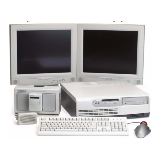
Information Center System Medium CRT Color Display Speaker 2 Channel Recorder 18.5 Keyboard Mouse Figure 1-3 Basic Information Center Client Workstation M3170 The M3170 Patient Link operates as a M3150 Information Center local database without a Patient Link display. The M3170 Patient Link provides a central location for bedside recordings and reports initiated from SDN hardwired bedsides, M2/3/4 bedsides and IntelliVue Patient Monitors. -
Page 31: M3154 Database Server
Information Center System The current workstation for Patient Link is shown in Figure 1-2. 2 Channel Recorder Figure 1-4 Basic Patient Link Workstation M3154 The M3154 Database Server is a Server that provides database storage of patient monitoring Database data for all devices on the Network. Information Center application software provides for Server storage of up to 96 hours of patient monitoring data (full disclosure waveforms, physiologic parameters, alarms, multi-lead arrhythmia, ST segments, and EASI 12-lead presentations) -
Page 32: Large Network Database System
XML format • HL7 formatted messages containing Information Center collected data can be output to an external HL7 compliant receiver • Alert Data Export • Interface to Philips/Zymed Holter for Windows Display Server Mouse Keyboard Figure 1-5 M3154 Database Server Large Up to ten M3154 Database Servers can be interconnected on the hospital LAN. - Page 33 Information Center System • Microsoft Windows XP Operating System • Information Center application software with database storage of the following data for up to 48 patients: – 24 hours of full disclosure waveforms (4 waveforms per patient) and physiologic parameters –...
-
Page 34: Topologies
Topologies Topologies Table 1-1 presents the applications available supported in each system configuration and Figure 1-7 and Figure 1-8 show these topologies. Note that these figures do not show the full system capabilities. Table 1-1. Topologies Alert Data Holter Review Pt Data Bed-Bed EASI... - Page 35 Topologies Native only Served by the Application Server Single or multiple M3154 Database Servers Across multiple M3154 Database Servers IntelliVue Clinical Network M2385 Application Server 100 Mbit/s HIS LAN for 10 Mbit/s web access 100 Mbit/s M3154 Database Server Wired IntelliVue Patient Monitor 18.5 HIS LAN for...
- Page 36 Topologies CareNet M3185 Clinical Network CMSs M3155 Information Center 12 patients LaserJet Printers 16 patients M3151 CareNet 10 Mbit/s Switch Clients 12 patients 100 Mbit/s 100 Mbit/s Network Switch CMSs M3155 Information Center 12 patients 16 patients 100 Mbit/s CareNet Telemetrys Switch M3151...
-
Page 37: Philips Carenet
Philips CareNet Philips CareNet Information Centers are designed to operate on Philips CareNet network, consisting of the Serial Distribution Network (SDN) and the Philips System Communications Controller (PCC/ SCC) or the CareNet Controller. See Figure 1-9. The Philips CareNet is a local area communications network designed to share patient physiological waves, parameters, and other data among bedside monitors, recorders, printers, and other computer systems. -
Page 38: Patient Monitors
The Information Center is designed to be compatible with recent Philips medical systems - bedside monitors, telemetry mainframes, central stations, and other computer systems compatible with Philips’ Serial Distribution Network. It can both send data to and receive data from SDN compatible instruments, recorders, and printers. - Page 39 2.6 and later Application Server A.01 and later Emergin Wireless Office Alarm Messenger 5.0 or greater The following Philips equipment is not compatible with Information Center systems. Table 1-4. Information Center Non-Compatible Equipment Product Name Product Number Software Release Monitor Terminal...
- Page 40 Patient Monitors Software Release Software Release Software Release Software Release PC Model Number Rel. D.0 Rel D.01 Rel E Rel E.01 D5765T Kayak XA-s Supported Supported Supported Not Supported D6723T Kayak XA Supported Supported Supported Not Supported D6731T Kayak XA Supported Supported Supported...
-
Page 41: Features
Features Features The Information Center is the central monitoring station that provides multipatient display of real time patient waveforms and physiologic parameters, annunciation of alarms and a wide variety of patient data storage and review functions, including full disclosure waves and parameters, alarms, ST segments, events, trends, and EASI 12-lead presentations. -
Page 42: Patient Window
Features Patient Additional data for each patient can be obtained in a more detailed Patient Window. Window Positioning the mouse cursor in a patient sector causes a Patient Window button to appear. Clicking on the Patient Window button brings up the Patient Window for that patient. The Patient Window can display up to 4 waves and 12 parameters for a single patient. -
Page 43: All Controls Window
Features All Controls The main control window for an Information Center is titled All Controls. It is obtained by Window clicking on the All Controls button in the Patient Window. The All Controls window provides control buttons for four major categories of Information Center applications: •... -
Page 44: Patient Data Storage
Features Caution The default Unit Settings Password is philips. This can be changed to a user- specified password via the service menu. See “Change Units Password” on page 7-76. It should only be used by persons responsible for setting unit wide configurations for monitoring patients. -
Page 45: Alert Data Export
Features • 10 configurable groups, up to 5 alarm criteria per group • strip displayed for verification of event criteria • total occurrences of alarms calculated and displayed in 1, 4, 8, 12, and 24 hour time scales ST Review: •... -
Page 46: Data Reliability
Features external software device of alarms is not confirmed and delivery to the end device is not guaranteed. Clinicians using Alert Data Export must remain within monitoring distance of the primary alarm notification device. The primary alarm notification device is either the bedside monitor (if present) or the Information Center. - Page 47 Server and review patient data Note All Philips Patient Monitoring products that operate in a LAN environment undergo industry- standard virus checking as part of the product manufacturing process. If installed as specified, the Information Center will not introduce a virus onto the hospital LAN. In order to allow the...
-
Page 48: Service
The Service Password is m3150. It is to be used by service personnel who are properly Notes trained and assigned to servicing Philips systems. It is the same Service Password as for Information Centers and Clients. All Service tools are in English only. -
Page 49: Configuration
• Other Services that provide Windows configuration tools and remote access capability • Shutdown for the controlled shutdown of Philips application software and access to the Windows Main Menu. • Maintenance applications for troubleshooting the network and the connected devices. -
Page 50: Patient Monitoring Configuration
Configuration menu in the Service function. On-Line Help To assist users in understanding and using Philips applications, extensive on-line Help features are provided. These Help screens give detailed descriptions of each application, including how to use its functionality, make configuration settings, and troubleshoot problems. - Page 51 Windows Help is provided as a standard part of Windows software for applications that are not part of Philips software. These Help screens are accessed from the Help button in the menu bar in the upper left of the window. See Figure 1-18.
- Page 52 Features These comprehensive on-line Help features provide quick and readily accessible information for understanding and properly using the Information Center’s extensive patient monitoring capability when and where it is needed. 1-28 Introducing the IntelliVue Information Center System...
-
Page 53: Clinical Applications
The Information Center can display the outputs of the variety of Plug-in modules that can be Modules used with Philips’ bedside monitoring systems some sample modules are shown below - refer to the Information Center Instructions for Use and to Table 1-6. -
Page 54: Waves And Parameters
VueLink Waves and The physiological monitoring capability of the Information Center system is given in the Parameters following table. The Philips Module column indicates the Plug-In Module source of the data Table 1-7. Information Center Patient Monitoring Capability Philips Waves... -
Page 55: Telemetry Monitoring
The M1403A/J Telemetry system provides ECG monitoring of 2 ECG waves with the ability to view up to 7 leads. M2600A Philips Telemetry provides ECG monitoring of 3 ECG waves of up to 7 leads. The M2600A also provides SpO measurements. -
Page 56: Alarm Annunciation
Clinical Applications available as an option for both systems, but it is not required when used with the Information Center because the Philips system provides ST Segment analysis of telemetry data as a standard feature. M1403A/J Digital UHF M2600 Philips... -
Page 57: Arrhythmia Monitoring
Clinical Applications • ECG recording is generated for preset periods preceding and following the alarm event (Red and Yellow alarms only) Figure 1-11 shows a typical Main Screen with patients in alarm. Note that Patient Sector CCU2 has the alarm message ***TACHY 160>140. Patient Sectors in alarm are backlighted in blue for easy identification, and the alarm message window is backlighted in the color of the alarm severity. -
Page 58: Basic Arrhythmia
Clinical Applications for heart rate and ventricular arrhythmia. Multi-lead arrhythmia monitoring is performed on the user-selected primary ECG lead and the secondary ECG lead. The following arrhythmia monitoring functionality is provided for both standard models of the Information Center system. For both models, beat annotation and rhythm and ectopic status messages are provided in the Patient Window. -
Page 59: St Segment Monitoring
ST segments can be analyzed for up to six leads of ECG monitoring, depending on the type of telemetry monitor and patient cable used, and for both non-paced and atrially paced patients (but not ventricularly paced patients). # Cable Philips Digital UHF Wires Telemetry... -
Page 60: Trend Review
Clinical Applications second alarm option for the Information Center. Each saved strip contains up to 4, 8-second, uncompressed waveforms and includes the date and time. Figure 1-21 Typical Alarm Review Window Trend Review Trend Review displays graphs or tables of patient physiological parameters that have been automatically stored during patient monitoring. -
Page 61: Event Review
Clinical Applications systems with dual display, 5 trend plots. Trend storage of 24 hours is standard with 48, 72, or 96 hours available as options. Figure 1-22 Typical Trend Review Window Event Review Event Review provides an overview of the frequency and duration of specific events, such as VTach, along with a strip of the waveform during the event. -
Page 62: Upgrades
Upgrades Upgrades The Information Center software can be upgraded from earlier releases. “Upgrade Options” on page 1-45 lists the upgrades. This section lists the requirements for software upgrades to release E.01. Memory The following memory upgrades are required when upgrading from an earlier release to Requirements release E.01. - Page 63 Upgrades Table 1-12. M3150 Hard Disk Requirements - VL400/420/D510 EASI Full Disclosure Req’d Disk Space (GB) Supported Upgrade No Upgrade Needed No Upgrade Needed Table 1-13. M3169 Hard Disk Requirements - D510 EASI Full Disclosure Req’d Disk Space (GB) Supported Upgrade Req’d No Upgrade Needed No Upgrade Needed...
-
Page 64: Bios Requirements
Upgrades Table 1-15. M3154 Hard Disk Requirements - LC2000/ML370 (A06) Req’d Disk EASI # IICs Full Disclosure Supported Drive Configuration (GB) Space (GB) 5x18 or 5x18/36 6x18 or 6x18/36 or 4x36 3x18 or 3x18/36 3x18 or 3x18/36 3x18 or 3x18/36 4x18 or 4x18/36 a. - Page 65 Upgrades the BIOS floppy disk is lost or has failed, a new one can be made. Refer to “Recreating Information Center BIOS Disk” on page 7-145. Table 1-17. Release E.01 BIOS Version Requirements - VL420/VL400 Platform BIOS Version VL420 JA.01.04US VL400 IP.01.08US 1-41...
-
Page 66: Components And Options
Modem (US Canada Only) Keyboard and mouse Uninterruptible Power Supply (UPS) 650 VA 650 VA 650 VA 1000 VA 650 VA Philips Recorder and Rack with 60V power supply Speaker (external) Isolation Transformer (Japan only) Software Description Windows Operating System software Workstation Workstation... -
Page 67: Purchased Options
Event storage with 1 hour strip function 24 hr 24 hr 24 hr Purchased Options available at the time of initial purchase of Philips systems for the basic models are Options given in Table 1-19. Purchased Options for the models are ordered under the following: •... -
Page 68: Channel Recorder Options
Options the model number indicated. Note Displays are sold separately. Philips will not install displays not supplied by Philips and cannot guarantee their compliance with ANSI/AAMI EC-13 or the EMC Directive. Table 1-22. Display Models for Information Center Systems M3150/... -
Page 69: Upgrade Options
Components and Options Upgrade The following options are available to upgrade Information Center systems to higher Options functionality after they have been purchased. Upgrade options are ordered under Product# M3150BU. Note A Customer Engineer must install upgrade options after they have been purchased and configure Information Centers to upgrade functionality. - Page 70 6-Way Video Splitter for 5 remote displays 862098 Keyboard-Video-Mouse Switch 862099 650VA Uninterruptible Power Supply (UPS) 98980313 Upgrade 24 hour to 48 hour CER to M3150B 1451 98980313 Upgrade 24 hour to 48 hour CER to M3154B 1461 98980313 Upgrade 24 hour to 48 hour CER to M3169...
-
Page 71: Printer Options
Components and Options Table 1-23. Upgrade Options for Information Center Systems M3150/ Option Description M3151 M3170 M3154 M3169 M3155 98980313 M3167BU PC Upgrade 1301 98980313 Trackball 1311 Printer Printer options available for Information Center systems provide printing capability. They Options are ordered under Product # M3159A. -
Page 72: Clinical Network Active Components
Components and Options Clinical Clinical Network active components are ordered under Product # M3185A Network Table 1-27. Active Components for M3185 Clinical Network Active Components Option Description Core Switch Edge Switch Extension Switch 10 Mbit/s UTP repeater 100-FX SC Transceiver (Fiber Port) for the Core and Edge Switches 10 Mbit/s media translator pair 100 Mbit/s media translator Wireless Access Point... -
Page 73: Cable Options
Components and Options Cable Cable options are available for interconnecting components. Philips devices come with Options standard length cables, but other lengths are available. Cable options for Philips systems are ordered under Product # M3181A. Table 1-29. M3181A Cable Options for Philips Systems... -
Page 74: Sdn Installation Materials
Part Numbers for components and options are provided in the Information Center Replaceable Parts List. Language Philips system software and workstation and server keyboards are available in the following Options languages. The desired language for both software and keyboard should be specified at time of purchase. -
Page 75: Hardware Description
Hardware Description Overview The IntelliVue Information Center system consists of proprietary M3290A Information Center Release E.01 software executing on Workstations and Servers running Windows Operating System software. To fully understand, utilize, and maintain these systems, support personnel should be familiar with Workstation and Server functionality and Windows Operating Systems. -
Page 76: System Components
IntelliVue Information Center Service Documentation CD-ROM. Warning Hardware and software products (including PCs, Servers, and network infrastructure) not supplied by Philips as part of an Information Center system are not approved or supported by Philips for use with Information Center and Clinical Network/Database Server systems. -
Page 77: M3154 Database Server
Following is a brief description of the features and components of the IntelliVue Information Center system: Mouse/Trackball Point and click capability for activating buttons and other control features on Philips screens is achieved with a standard computer interface mouse or trackball. The mouse is provided as standard equipment, but a trackball can be ordered as a purchased or upgrade option. -
Page 78: Display
For dual display installations, another video card may be required. This is installed in the factory if the dual display option is a purchased option, but must be installed by a Philips customer engineer if an upgrade option. The Dual Display Upgrade Installation Note provided with the option describes the installation procedure. -
Page 79: Modem
System Components Modem A modem is provided for linking the Server to an external telephone line. This permits access to the Database Server for system troubleshooting by service personnel distant from the installation. An analog modem is standard for M3154 US and Canadian installations only. In other countries, the customer is responsible for selection, purchase, installation, configuration, and maintenance of an external modem. -
Page 80: Panel Descriptions
System Components Panel Descriptions Sound Card Hospital LAN SDN Card NIC Card (Optional) Second Serial Dual Video Card Connector (COM B) (Optional) 10BT 100TX LAN Connector Voltage Select Switch Power Cord Connector Mouse Connector Display Connector (not used if Dual Display) Keyboard Connector Parallel Connector First Serial Connector (COM A) - Page 81 System Components 4-Channel Recorder or Speaker Ext. Modem Hospital LAN NIC Card (Optional) (Optional) Y-Cable (Dual Display) 10BT 100TX Printer Clinical Network 2-Channel Mouse Main Display Recorder Rack (Single Display) Keyboard See Note Figure 2-5 Plug Connections for D510 Information Center Systems Note For Single Display systems, the Main Display is plugged into the 9-pin Main Display connector on the rear of the PC.
- Page 82 System Components Second LAN Card for Hospital LAN (Optional) LAN Connector for Clinical Network Parallel Connector Display Connector Serial Connector A Power Cord Connector Serial Connector B Mouse Connector Keyboard Connector Disk Eject Button Disk Drive Disk Activity LED Unit Identification LED (UID) Switch and LED Internal System Health LED External System Health LED...
-
Page 83: Displays
System Components Displays There are two different size CRT displays and a flat panel display available for viewing patient data and control screens for each Information Center model. Displays are ordered separately by model numbers. Each model can also accommodate remote slave displays for viewing information at distant locations. -
Page 84: Flat Panel Display
System Components Flat Panel A large color flat panel display is also available as a purchased product. It has a screen Display resolution of 1280 x 1024. The flat panel display is shown in Figure 2-9. Front and rear panel views are shown in Figure 2-10. -
Page 85: Dual Display Option
90 m (300 ft.) are supported. The Remote Display is a slave display that simply displays the window showing on the Philips display it is paired with. Up to 6 Remote Slave Displays can be connected to an Information Center system using the proper Video... -
Page 86: Keyboard-Video-Mouse Switch
System Components Splitter uses AC line power. The video output of the processing unit connects to the 5 BNC Video Splitter inputs and the displays connect to the 5 BNC Video Splitter outputs. Universal Power Supply 2 Video Outputs DC in Video Inputs 2-way Video Splitter... -
Page 87: Philips Recorder Systems
• M1116B #201 Thermal Array Recorder Module, a double-width module • M1276A #201 Recorder Rack, which can house up to 3 Philips Recorders • Bracket Stand Assembly, which provides a stable support for the Recorder Module and Rack on a flat surface •... -
Page 88: Recorder Module
Power Supply Bracket Stand Assembly Figure 2-15 Philips 2-Channel Recorder System Recorder Module The M1116B #201 Thermal Array Recorder Module is a thermal array recorder that provides high resolution, high quality waveforms. The grid and waveforms are printed simultaneously to assure accurate registration. It has recording capability for up to three... - Page 89 System Components The front panel of the Philips M1116B Recorder Module is shown in Figure 2-16. The front panel indicator and controls do the following: 1 - Continue Indicator - An LED that blinks twice when the module is first plugged in, indicating that the recorder self-test has completed successfully.
- Page 90 Recorder Rack Power Supply Fault No Recorder Recorder Rack The M1276A #201 Recorder Rack is designed specifically for the Information Center system. It holds up to three model M1116B Philips Recorders, but cannot be daisy chained for additional Recorder capability.
-
Page 91: Recorder Rack
The operation of the M1276A #201 Recorder Rack and M3180-60040 60VDC Power Supply are described in the Philips M1276A #201 Parameter Module Rack Service and Installation Guide. The following table lists the components of the Philips Recorder System. Table 2-1. Philips Recorder System Components... -
Page 92: Speaker
System Components Table 2-1. Philips Recorder System Components Philips Part Number Description M2300-40011 Rack Blank Panels (2) M3180-60400 Bracket Stand Assembly M3180-60040 60VDC Power Supply M3180-60170 Recorder Cable 1m to PC/3m to rack standard M3180-60150 Recorder Cable 1m to PC/6m to rack optional... - Page 93 System Components The M3160 4-channel recorder includes a 24 Vdc power supply and cable, a serial interface cable, and a box of 24 rolls of paper. Refer to the table below for items included with the M3160 4-Channel Recorder. Part Number Description M3160A 4-Channel Recorder with 24Vdc Power Supply and Cable...
- Page 94 System Components Figure 2-21 Philips 4-Channel Recorder Controls and Indicators A. Power ON/OFF Switch B. Power ON Indicator Illuminates when power is on C. Paper Empty Indicator Illuminates when the paper has not been properly set or when there is no paper.
- Page 95 BIOS Settings - Changes may be required to the BIOS settings when a 4-channel recorder is added. Refer to “Updating BIOS” on page 7-119. 4 - Channel Recorder to UPS AC Output to Serial B Port Interface Cable to PC Workstation 24V Power Supply Figure 2-22 Philips 4-Channel Recorder Rear Panel Connections 2-21 Hardware Description...
-
Page 96: Printer
System Components Printer An HP LaserJet Printer with connectivity to the Network (Option M3159A #A02) is available for printing patient and configuration data. The Printer is connected to a Switch port via a 10 Mbit/s, UTP cable. The Network connection is made via a JetDirect, 10BaseT Ethernet card, which is included with Option M3159A #A02. -
Page 97: Printer Hub
Printer Hub. This connection is 10 Mbps. The connection must be changed using the procedure given in “Device Name” on page 5-35. Philips CareNet monitors (Component Monitoring System (CMS), 24 Monitors, and Telemetry Monitors) are the only bedsides supported on the Printer Hub. Patient monitors that connect directly to the Clinical Network (wired/wireless M2/M3/M4/IntelliVue Patient Monitors) are not supported on the Printer Hub. -
Page 98: Uninterruptible Power Supply
(e.g. power generation tests). Caution The Philips 9 pin UPS communication cable (gray) must be used when connecting the devices to the UPS. Do not use the black COM cable that ships with the UPS. Warning UPSs are shipped without their internal battery wire connected. - Page 99 System Components The UPS for the M3154 Database Server is 1000 VA and comes in 3 versions -- 100 VAC (50-60Hz), 120 VAC (50-60 Hz), and 230 VAC (50-60 Hz). It is shown in Figure 2-26 along with typical front and rear panels. 1000 VA UPS Test Switch...
-
Page 100: Operation
Seconds after power failure Action Line power fails and UPS goes to battery power. Philips systems continue to run, but displays will be blank (no power). If line power returns during this 90-120 second period, normal operation is restored automatically. -
Page 101: Power Distribution Module
System Components Power A Power Distribution Module (M3166A) is provided with all Japanese orders to comply Distribution with Japanese regulatory requirements. It is designed to accept selectable input voltages from Module 100V to 240V (at 50-60 Hz) and produce selectable low output voltages of 100-127 V and selectable high output voltages of 200-254V. - Page 102 System Components • J3-J6: additional output receptacles that are either high or low voltage depending on the position of switch S3 S3: sets voltage output of J3-J6 high if set to 240/240-254/240/220-240 V~ • sets voltage output of J3-J6 low if set to 120/120-127/120/110-120 V~ •...
-
Page 103: Mounting
Mounting Mounting A variety of hardware is available for mounting Information Center components for convenience of use and efficiency of the work area. Display Display mounts are available to permit easy viewing of video screens in a variety of locations Mounts and directions. -
Page 104: Computer System Mounts
Mounting Computer When using Information Center systems in a clinical environment, only some of the System components need to be available to the user - display, keyboard, mouse, speaker, recorder, Mounts printer. The other components - processing unit, UPS, power supplies, video splitter - can be placed in an out-of-the-way location to minimize clutter in the central monitoring area. -
Page 105: Ups Mount
Mounting UPS Mount Wall mount hardware for the UPS, 60V Recorder Power Supply, and 2-way Video Splitter is shown in Figure 2-33. Wall Mount Bracket Wall Channel Bracket 2-way Video Splitter 60V Power Supply Bracket Bracket Wall Mount Assembly Detail Wall Mount Assembly Mounting Cover Wall Mount Assembly with Cover... - Page 106 Mounting The processing unit and UPS system mounts can be combined for a single wall mount installation as shown in Figure 2-34. Note that the installation can be mounted either vertically or horizontally, depending on the space available. Horizontal Mount Vertical Mount Figure 2-34 Combined Wall Mount Options A table of optional mounting hardware is given in Chapter 1, Mounting Options.
-
Page 107: Carenet
CareNet The Information Center is designed to display data from bedside and telemetry monitors connected to Philips CareNet, which consists of the Serial Distribution Network (SDN) and 78581 System Communications Controller (SCC), or the new CareNet Controller depending upon which version of controller you have. The controller manages communication between the Information Center and devices connected to the SDN. -
Page 108: Serial Distribution Network
CareNet Serial The Serial Distribution Network (SDN) is a local area communication network designed to Distribution share patient information -- waveforms, parameters, alarms -- among devices connected to the Network network -- patient monitors, central stations, displays, recorders, printers, and other computer systems. - Page 109 CareNet Branches 1-24 Patient Monitoring Devices Branch 0 Philips Information Center Branches 30-31 Branches 25-29 Computer Systems Telemetry Mainframes, Central Stations, Careports Figure 2-35 SDN Topology 2-35 Hardware Description...
-
Page 110: System Communications Controller
CareNet System The System Communications Controller (SCC) is the active device of the SDN. Its Communicatio functions are to provide the communication link among instruments connected to the SDN, ns Controller establish SDN polling cycles, and control data flow, timing, synchronization, and distribution throughout the system.The SCC is shown in Figure 2-36. -
Page 111: Sdc
Philips proprietary computer cables with a 9-pin connection to the processing unit and an Philips 5-pin barrel connector to an Philips SDN wall box. A 15 m (50 ft.) LDC cable kit (M3181A #A35) is also available. Cables and wall boxes are described in the following sections. -
Page 112: Wall Box Kits
Wall box kits for connecting Philips LDC to SDN/UTP wiring are available from Philips. These are special Philips wall box kits designed to fit into standard U.S. electrical wall boxes [NEMA, single or dual gang with conduit knockouts, minimum depth = 4.0 cm (1.6 in.)] and typical European wall boxes [minimum depth = 4.0 cm (1.6 in.)]. -
Page 113: Cables
Cables Cables Equipment cables for Philips devices are of two general types, those that provide power and those that carry communication signals. This section provides descriptions and drawings of each cable. Detailed wiring diagrams for each Information Center model are provided in Chapter 5, Installation. - Page 114 Cables Table 2-3. Equipment Cables for Information Center Systems Key # Description Option Length (m) Length (ft) Printer Spooler - PC cable (options) 32.8 4-Channel Recorder 24V Power Supply power cable 4-Channel Recorder signal cable SDN 9-pin D from SDN Card to standard CAT 5 UTP faceplate (RJ-45 connector) SDN 9-pin D from SDN Card to standard CAT 5 UTP 13.1...
- Page 115 Cables Display AC Power Display AC Power Main Screen Display Slave Display Hardwired to Mouse or Trackball Hardwired to Keyboard AC Power (UPS) Printer (A01 Option) Figure 2-40 Equipment Cables for Information Center Systems 2-41 Hardware Description...
-
Page 116: Cable Pin Connections
Display Figure 2-41 Equipment Cables for IntelliVue Information Center Systems Cable Pin Pin connections for cables connecting Information Center medical components -- Philips Connections Recorder and SDN -- are given below. For pin connections for other products and cables, consult their documentation manual. -
Page 117: Recorder Rack/Power Supply Cable
Cables Recorder Rack/ Pin connections for cables interconnecting the Philips Recorder and 60VDC Recorder Power Power Supply Supply are given in Figure 2-42. Cable Socket Socket 11 - Inner Shield 1 - Orange: ADDR_A 12 - 2X Blue Inner: POWER GROUND... -
Page 118: Sdn Wall Box And Signal Cable
Cables Socket 4 Socket 1 AC Power (UPS) Socket 2 Socket 3 Socket 1:Black Power Ground Socket 2: 4-Channel Recorder Socket 3: Outer Shield Socket 4: Red: 24VDC 24 VDC Power Supply Pin 9 Pin 5 Pin 5 Pin 9 Pin 1 Pin 6 4-Channel Recorder... - Page 119 Cables connections A (+) and E (-) of the SDN wall box socket. The other UTP cable pairs are connected to ground. UTP Cable SDN Wall Box to SCC WHITE/blue: Data Wire (-) BODY BLUE/white: Data Wire (+) All others: Ground stripe Socket A...
-
Page 120: Computer Cards
Computer Cards Computer Cards Within a typical Information Center processing unit there are four PC cards that tailor the system to Information Center applications. These are a Dual Video Graphics Card (for M3150 systems), the PC System Board (mother board), an Audio Sound Card, and an SDN Card. -
Page 121: Audio Sound Card
Computer Cards Note Single Display systems - the Main Display is plugged into the 9-pin Display Connector on the rear of the PC. Dual Display systems - a Dual Video Card is required. The provided Y-Cable plugs into the 9- pin Display connector on the Dual Video Card. -
Page 122: Specifications
5.1 (2.0) 46.4 (18.3) 17.8 (7.0) 1.1 (2.4) Keyboard-Video-Mouse Switch 862098 4.8 (1.9) 20.6 (8.1) 12.7 (5.0) .77 (1.7) Philips 2-Channel Recorder/Rack M1276A #201/ 14.9 (5.9) 26.0 (10.2) 15.0 (5.9) 1.6 (3.5) M1116B 2-Channel Recorder/Rack Power Supply M3180-60040 40.3 (15.9) 7.75 (3.05) -
Page 123: Environmental
Environmental The following table gives information on the environmental operating requirements for the current system components. Data for both the Philips system as a whole and for individual components are provided. Table 2-5. Environmental Requirements for Information Center System Components... -
Page 124: Electrical
Philips 2-Channel Recorder/Rack M1276A #201/ 60 VDC M116B 2-Channel Recorder/Rack Power M3180-60040 100 - 240 50 - 60 Supply Philips 4-Channel Recorder/ 24VDC M3160A 100 - 120 50 - 60 Power Supply 220 - 240 LaserJet Printer 2300L 100 - 127... -
Page 125: Customer Supplied Displays
Information Centers and Clients. Displays Note For displays and video cables not supplied by Philips as part of an Information Center system: • The support user is responsible for all aspects of their selection, purchase, installation, repair, and disposal •... -
Page 126: Flat Panel Specifications
Specifications Table 2-7. Recommended Display Specifications for Information Center Displays Specification Value Note—This value is the Visible Display Width that is entered in the Viewable width of 1280 dots Config Wizard Device Setup and Support Information Screen. The valid range is 267 to 1188 mm. Some typical values include: •... -
Page 127: External Modem
Modem Center PC Workstation and the M3154 Database Server. Note For external modems not supplied by Philips as part of a Philips system: • The support user is responsible for all aspects of modem selection, purchase, installation, repair, and disposal •... - Page 128 Specifications Caution To minimize potential problems, the modem phone line cable should be disconnected when not in use. Note The Windows Catalogs are replacing the Hardware Compatibility List (HCL). Step 1. Go to the Windows Catalogs URL: www.microsoft.com/whdc/hcl/default.mspx. Step 2. Click on the appropriate link: •...
- Page 129 Specifications Table 2-8. Requirements for an External Modem Specification Value Comments Pin 2 RX (Receive Data) Pin 3 TX (Transmit Data) Pin 4 DTR (Data Terminal Ready) Pin 5 GND (Signal Ground) Pin 6 DSR (Data Set Ready) Pin 7 RTS (Request To Send) Pin 8 CTS (Clear To Send)
-
Page 130: Regulatory
IEC 60950, CISPR 22 Level A, and EN 50082-1. They carry CE- marking to the European Low Voltage and EMC Directives, except for the Philips 2-Channel Recorder, which carries CE-marking to Council Directive 93/42/EEC of 14 June 1993. -
Page 131: Software Description
Software Description Overview The Information Center medical application software is the heart of the Information Center. It operates on an PC workstation and uses a Windows Operating System software to provide the full range of central monitoring functionality. Chapter 3 describes the system application software in the following sections. •... - Page 132 • video adapter: 1280 x 1024 pixels The PC Workstation supplied by Philips have been configured, tested and validated to meet the specific medical device requirements for operating the application software. Therefore, they are the only hardware approved for use in Information Center systems.
-
Page 133: Peripheral Devices
PC Workstation Platform Peripheral Devices In addition to the PC, the Information Center hardware platform includes a variety of peripheral devices that are compatible with it and achieve the desired performance. These include input devices (keyboard and mouse), output devices (displays, speaker, recorder and printer), and networking (SDN/SCC/PCC), as well as supporting hardware such as the UPS and Power Distribution Module. -
Page 134: Windows Operating System
Application Programming Interfaces (APIs). The Operating System and its APIs are described in detail in Microsoft Windows documentation but only briefly here. Philips support personnel are encouraged to gain knowledge of these subjects through the variety of OS documentation and training programs available. -
Page 135: File System
Windows Operating System The OS also provides two principal software management functions for Information Center software -- File System and Registry (and its peripheral hardware drivers). See Figure 3-4. Audio Display Driver Driver Printer Keyboard File Registry Driver Driver System Network Mouse Adapter... - Page 136 Windows Operating System A diagramatical representation of the Registry for the OS is shown in Figure 3-5. Setup Hardware Programs Data Registry Windows Device Kernel Drivers (NTOSKRNL) Figure 3-5 Windows Use of the Registry The Registry is constructed from the following components of the Windows OS: Hardware Data - When Windows starts, the Registry obtains volatile hardware configuration data -- hardware information detected in the computer.
- Page 137 Windows Operating System A diagramatical representation of the Registry for Information Center software is shown in Figure 3-6. Registry Philips SDN Interface Installation Driver Figure 3-6 Information Center Software Use of the Registry Functioning of Registry components for Information Center software is as follows:...
-
Page 138: Intellivue Information Center Application Software
IntelliVue Information Center Application Software IntelliVue Information Center Application Software Application software is the central component of the Information Center system. Application software is contained on one IntelliVue Information Center Application Software CD ROM and Operating System software is contained on another, and both CDs can be loaded into the PC Workstations for both Information Center models using the processing unit’s CD ROM drive. -
Page 139: Modes Of Operation
IntelliVue Information Center Application Software Modes of Application software has two modes of operation -- Monitoring Mode and Non- Operation monitoring Mode. Monitoring Mode Monitoring Mode is the principal mode of operation in which application software provides centralized monitoring, alarms, storage, and review of patient information obtained from LAN based bedsides and bedside and telemetry monitors connected to the SDN. -
Page 140: Architectural Design
Monitoring Mode Applications are primarily clinical applications that provide clinicians with information about their patients and are visible on the Philips display. The Main Screen is the primary clinical application and is always visible during Monitoring Mode. All other clinical applications become visible in the Patient Window area of the screen when the operator requests them. -
Page 141: Applications
IntelliVue Information Center Application Software IntelliVue Information Center System Application Software APPLICATIONS Applications Library Sound Applications Manager Manager Manager SERVICES Database Alarm Physio Services Services Data Server SDN Data Measurement Acquisition Services Services Recorder Documentation Interface Services Services Windows Operating System Display Audio Driver... -
Page 142: Applications Library
IntelliVue Information Center Application Software Applications Philips Applications Software consists of an Applications Library of the following Philips Information Center applications: • Real-time Applications • Control Applications • Review Applications • Support Applications and the following Management Functions for managing the Philips input devices (keyboard, mouse) and output devices (display, speaker): •... -
Page 143: Real Time Applications
IntelliVue Information Center Application Software Applications Library Applications Library software does the following: Real Time Real Time Applications control the display of real time patient data from bedside Applications and telemetry monitors on the Main Screen and Patient Window, shown in Figure 3-11. - Page 144 IntelliVue Information Center Application Software the All Controls window. See Figure 3-12. This functionality requires a password for access. Unit settings apply to all patients unless overridden by the individual patient Control Application. When a patient is discharged, the clinical unit settings automatically replace the individual patient’s custom settings.
-
Page 145: Review Applications
All Controls window. Each review application obtains its specific data for an individual patient from Database Services and presents it in the Patient Window display or delivers it to the Philips recorder or printer when requested. Review Applications include the following for each patient. -
Page 146: Management Functions
IntelliVue Information Center Application Software • Configuration/Installation Applications • Remote Access • Telemetry Services • Option Utilities They are described in more detail in the following section, Services. Management Management Functions software does the following: Functions Application Manager Application Manager (SDProcess) controls when an application is allowed to use (SDProcess) the display area and is responsible for initiation and termination of applications. -
Page 147: Physio Data Server (Pdsservice)
IntelliVue Information Center Application Software Services software is shown in the block diagram of Figure 3-13 and described in the following sections. Information Center Services Applications Manager Patient Alarm Database Services Services Physio Data Server Measurement Services Recorder SDN Data Documentation Management Status... -
Page 148: Measurement Services
IntelliVue Information Center Application Software Patient Database Services showing its interface with the Operating System and processing unit hard disk is shown in Figure 3-14. Applications Manager Patient Database Physio Alarms Services Data Server Measurement Recorder Database Interface Application Software File Registry System... -
Page 149: Alarm Services
Documentation Status Documentation Status Services (DocStatus Service) provide documentation control Services services to both the Philips Recorder and the LaserJet printer. It receives data from (DocStatusService) Recorder Management Services and provides output interfaces to both the Philips Recorder and the printer through the Windows Print Manager. The data can be either real-time patient data from bedside or telemetry monitors or stored patient data from Database Services. -
Page 150: Recorder Documentation Services
IntelliVue Information Center Application Software Recorder A functional block diagram of Documentation Status Services for the Philips Documentation Recorder is shown in Figure 3-15. Services Applications Manager Physio Data Server Documentation Recorder Status Manager Services Shared Memory Redirector Driver Serial B... -
Page 151: Printer Documentation Services
IntelliVue Information Center Application Software SDN Driver moves data back and forth between Recorder Services and the Recorder. SDN Interface detects the position (L, C, R) of each recorder in the recorder rack, determines recorder status, and conveys data for recording. In multiple recorder operation, a recorder that is busy or off-line goes to the bottom of the recorder queue and the next available recorder is selected. - Page 152 IntelliVue Information Center Application Software 3-22 Software Description...
-
Page 153: Site Planning And Preparation
Center system will focus principally on the unique requirements of installing Information Center hardware as the central station component. The Database Server is one of the “hidden” components of the Philips Patient Care Network. The Database Server is generally located in out of the way equipment rooms or wiring closets. -
Page 154: Site Planning
Planning and preparing the site for an installation is a joint responsibility between the Customer and Philips. Sales and Support Representatives are available for consultation and assistance in each of the areas above. To assure that the system is properly designed and... -
Page 155: Philips Factory
Philips Factory The Philips Factory is responsible for assuring shipment of a fully configured Philips product including: • all ordered system hardware, network components, and peripheral equipment fully tested and ready for installation •... -
Page 156: Location
• workstations for all Small Database Servers, Information Centers and Clients • Philips 2 Channel and 4 Channel Recorders Up to 3 Clinical Network components -- switches, repeaters, media translators -- may be connected to a single, 650VA UPS. It is recommended that Access Points and Repeaters also be connected to a 650 VA UPS. -
Page 157: Other
Site Planning The following components may be connected to the ACCESSORY outlets of a 650 VA UPS or to a separate non-UPS electrical outlet with the same ground. • displays • video splitters • printer spooler • paging components The LaserJet Printer must not be connected to the UPS. Other Other issues to consider when selecting device locations include the following: •... -
Page 158: Network Design
Network Design Network Design This section describes the methodology for designing a Philips Patient Care Network for a specific clinical environment. It includes the clinical issues that should be considered, the capabilities of the Information Center components, and the design rules that govern Patient Care Network design. -
Page 159: Future Capability
Hence, consideration should be given to possible future growth or requirements in system design. Review this thoroughly with a Service Provider. Philips The design also requires a full understanding of the capabilities and limitations of network Hardware components so they can be properly matched to the clinical requirements. -
Page 160: Carenet
Philips 24 patient monitor with more limited monitoring capability, or the older Compact Configured Monitor. Telemetry Monitors can be Philips Telemetry system or the older model Digital UHF Telemetry system. Each telemetry mainframe can accommodate up to 8 telemetry monitors, 1 per patient. -
Page 161: Central Monitoring Stations
Note M2350/60A CCMs (release B.03.13) that monitor telemetry with release 2.x cannot connect to the same Philips Communications Controller (PCC) as the Information Center systems (release C.0 and later). This unsupported configuration will cause loss of all telemetry patients being monitored, and Standby and ECG size control will be unavailable at the Information Center. -
Page 162: Printers
Patient monitors for both systems can be hardwired or telemetry. • Telemetry mainframes can support 8 channels of telemetry monitoring. These design capabilities and limitations are summarized in Table 4-2, Philips Patient Care Network Component Capabilities and Limitations. Table 4-2. Philips Patient Care Network Component Capabilities and Limitations... -
Page 163: Designing The System
Design This section shows schematic designs of typical independent Information Center systems as Examples examples of how the Philips Patient Care Network can meet the needs of a wide range of clinical environments. Small ICU A simple Philips Patient Care Network is for an 8-bed ICU with intensive patient monitoring requirements for all patients and the possibility of transferring up to 2 patients to telemetry. - Page 164 Network Design Equipment required for this installation is the following: • 8 beds, each with a hardwired bedside patient monitor • 2 telemetry monitors on one telemetry mainframe • 1 Information Center with 8 patient (Option #A08) and full alarm and wave review capability •...
-
Page 165: Large Icu
Network Design Large ICU The next example is a large, 20-bed ICU with intensive monitoring requirements for all patients and the ability to transfer up to 4 patients to telemetry. See Figure 4-3. Equipment required for this installation is the following: •... -
Page 166: Medium Stepdown Unit With Telemetry Monitoring
Network Design Assignment of telemetry monitors to specific Information Centers is recommended because information that a telemetry monitor is being used by another Information Center is not shared across the SDN. Hence, a telemetry monitor used by another Information Center will appear as available in the Sector Setup window. - Page 167 Network Design • 2 Information Centers, each with 12 patient (Option #A12) capability • 1 System Communications Controller In this example, 24 beds and 12 telemetry monitors are assigned to each Information Center. The bedside and telemetry monitor assignments are unique to each Information Center because Information Centers do not communicate with each other as to which monitors are currently being used.
-
Page 168: Very Large Stepdown Unit With Telemetry Monitoring
Network Design Very Large When the number of patient monitors in a Stepdown Unit exceeds 24, a second System Stepdown Unit Communications Controller is required. This is shown in Figure 4-6. with Telemetry Equipment for this installation is the following: Monitoring •... -
Page 169: Telemetry Monitoring Without A Scc
SCC. Therefore, when only telemetry monitoring is Without a SCC required, the SCC may not be required. This can reduce the cost of some of the Philips Patient Care Network designs described earlier. The Medium Stepdown Unit with Telemetry Monitoring, for example, could be more simply redesigned as shown in Figure 4-7. -
Page 170: Database Server Systems
This manual does not describe the design and implementation of DBS Server systems in detail because each clinical environment requires careful analysis by an experienced network designer. Philips Service Providers are specially trained to assist customers in reviewing their clinical requirements and designing a Server system that meets those requirements and will be supported by Philips Medical Systems. -
Page 171: Guidelines
Network Design Guidelines This section describes the guidelines to be followed when designing a DBS system. Two examples are given: one is a single switch network and the other is a multiple switch network. These examples describe hardware design only. Hardware installation is described in the following section, and the application software configuration is described in Chapter The basic principles in designing the network design are: •... -
Page 172: Site Preparation
Site Preparation Site Preparation This Section gives more detailed information on the preparation of a site for IntelliVue Information Center system installations. Equipment The Information Center system should be centrally located in the clinical environment so that Location nursing staff have convenient and ready access to the Information Center display, where patient information is available, and to patients’... -
Page 173: Typical Installations
Site Preparation Typical Typical worksurface installations are shown in Figure 4-9. Installations Note Items not shown are assumed to be located elsewhere. The space, weight, environmental, and electrical requirements for these examples are given in the tables following. The data for these tables are derived from the Specifications for individual units given in Chapter 2. -
Page 174: Environmental Requirements
Site Preparation 4-9, consult Table 4-3, Space and Weight Requirements for Information Center Installations and/ or the documentation for the units that comprise the system. Table 4-3 Space and Weight Requirements for Information Center Installations Height Width Depth Weight # Power System cm (in.) cm (in.) -
Page 175: Electrical Requirements
Site Preparation Electrical The following table gives electrical requirements for the Information Center installations Requirements shown in Figure 4-9. To determine similar specifications for Information Center installations different from those in Figure 4-9, consult Table 4-5 and/or the documentation for the units that comprise the system. -
Page 176: Windows 2000
Site Preparation The following settings must be determined before installation: IP Address Subnet Mask Default Gateway DNS IP Address (search order) WINS IP Address primary secondary Note These 2nd NIC Adapter Card settings are site-specific. These settings should be documented clearly and be available in case the device has to have the Operating System re-installed. -
Page 177: Windows Xp
Site Preparation Step 5. Click on the Advanced button and click on the DNS and/or WINS tabs to enter in the DNS/WINS settings if required. Figure 4-11 Windows 2000 Hospital LAN TCP/IP Advanced Settings Windows XP Step 1. Go the Start Menu, and select Settings - > Network Connections Step 2. - Page 178 Site Preparation Step 5. The TCP/IP Properties, including the IP Address, Subnet mask, Default Gateway and DNS settings can be entered. Figure 4-12 Windows XP Hospital LAN TCP/IP Settings Step 6. Click on the Advanced button and click on the DNS and/or WINS tabs to enter in the DNS/WINS settings if required.
-
Page 179: Equipment Cabling
Relevant IEC standards are IEC 60950 for computer equipment and IEC 61010 for laboratory equipment. Philips Device Philips workstations, server, displays, LaserJet printers, and active Network components may Requirements be connected to bedside monitors through the Clinical Network and SDN provided that they are located outside the patient environment and provided that the PCC or telemetry mainframe contains a redundant Protective Earth connection. - Page 180 Site Preparation 1.5 m (4.9 ft.) 1.5 m (4.9 ft.) 2.5 m (8.2 ft.) 1.5 m 1.5 m (4.9 ft.) (4.9 ft.) Figure 4-14 Limits of the Patient Environment 4-28 Site Planning and Preparation...
-
Page 181: Hardware Installation
Network Names and IP Addresses ....page 5-33 Cable Plant Philips requires that the customer contract with a certified CAT5 cable installer for cable Installation plant installation and that the installer provide test documentation that demonstrates that the cable plant meets required specifications. -
Page 182: Utp Cable Plant Installation
Overview The noise immunity of fiber optic cable is superior to UTP cable so that fiber optic cable should be used for any 10 Mbit/s cable runs over 100 m for which RF or electrical noise is a potential problem. UTP Cable Plant A typical cable plant installation for UTP Category 5 cables for Information Centers, Installation... -
Page 183: Connections
Printer Hub (optional) • Video Splitter (optional) PCs are opened at the Philips factory and interface cards and operating system and application software installed and tested. They are then repackaged for shipment to customers along with other IntelliVue Information Center hardware. -
Page 184: Unpacking Components
The Philips Service Provider assigned to the installation will remove the components from their packaging and assure the integrity of the shipment. The Philips Service Provider will also remove shipment packaging materials from the customer site if requested. -
Page 185: Inspection
Overview Inspection The Information Center system has been carefully packaged at the Philips factory so that no damage should occur in shipment. However, Philips has no control over shipping and handling after it leaves its facility, and a thorough inspection of Philips components after removal from their packaging is an essential step to assuring that no damage has occurred. -
Page 186: Locating System Components
Locating System Components Locating System Components This section describes proper installation of the components of the Information Center system in their intended locations, including the assembly and installation of mounting hardware. The procedure for a particular installation depends on the planned locations of individual components developed during site planning and preparation in Chapter 4. -
Page 187: Keyboard Mounting Options
Locating System Components The procedure for mounting the swivel mount hardware and display is described in detail in the Installation Note supplied with that option. Figure 5-6 M3180 #A05 Permanent Swivel for Medium CRT Displays Keyboard Two work surface installation options are available for the computer keyboard -- a table top Mounting garage (PN M3180A #A09) and an under table drawer (PN M3180A #A08). -
Page 188: Component Mounting
Wall Brackets Attachment of wall mount hardware to ceilings and walls requires the secure attachment of a wall bracket to a building structural member. This is to assure that the installation can safely and securely support the weight of the mounted hardware. The Philips supplied wall bracket is shown in Figure 5-8. - Page 189 Locating System Components Ceiling and Wall For installations in which mounting the medium or large CRT displays to a wall or ceiling Mounts for provides better patient monitoring convenience, display mounting hardware is available. Displays Ceiling and wall mounts are particularly useful for locating remote displays. A wall mount (only) is also available for the large, flat panel display.
-
Page 190: Wall Brackets
Locating System Components for this wall mount are described in the Power Distribution Module Installation Note supplied with the PDM: Wall Bracket PDM Enclosure Figure 5-10 Wall Mount for Power Distribution Module 5-10 Hardware Installation... -
Page 191: Information Center Installation
Locating System Components Information The final step is to install all Information Centers, Clients, and their peripheral equipment -- Center displays, keyboards, mouses, video splitters, keyboard-video-mouse switches, recorders, etc. Installation in their planned locations. Rear panel cabling connections for Information Center workstations are shown in Figure 5-11. -
Page 192: D510 Power Switch Cover
– Verify the UPS Switch settings are accurate, see page 2-25. – Connect the Philips 9 pin UPS communication cable (gray) to the computer interface port of the UPS and the Serial A port on the rear of the PC. See Figure 5-11. - Page 193 Locating System Components Bracket Speaker Plug Cable Tie Strain SDN Plug Relief (secure) Loop Mouse/ Trackball Plug UPS Plug Keyboard (secure) Plug Cable Tie Power Plug Strain Relief Loop Stick-on Tie Mount Figure 5-13 Securing Cables on Information Center and Client PCs 5-13 Hardware Installation...
-
Page 194: M3169 Small Database Server Installation
– Verify the UPS Switch settings are accurate, see page 2-25. – Connect the Philips 9 pin UPS communication cable (gray) to the computer interface port of the UPS and the Serial A port on the rear of the Server. See Figure 5-14. -
Page 195: M3154 Database Server Installation
– Connect the Server power cord to a UPS battery backup outlet. – Connect the Philips provided 9 pin UPS communication cable (gray) to the computer interface port of the UPS and the Serial A port on the rear of the Server. -
Page 196: Printer Installation
Locating System Components Printer Install all printers that connect to switches as follows: Installation When connected to a network, a JetDirect, 10Base-T Ethernet card must be installed in the LaserJet Printer. This card comes with Option M3159A #A02. A 10 Mbit/s, UTP cable with an RJ-45 connector is then used for the connection. - Page 197 Locating System Components Graphical Display Help button Up button Select button Back button Down button Pause/Resume Cancel Job button button Ready Data Attention Figure 5-17 Front Panel Controls 25 Pin Parallel Connection RJ-45 LAN Connection Jet Direct Card Figure 5-18 Rear Panel Connections Note For proper operation, the CONFIG METHOD of the LaserJet Printer must be set to *BOOTP.
- Page 198 Locating System Components • press the Down button to scroll through the Control Panel menu to display the Configure Device menu and then press Select. • press the Down button to scroll through the Configure Device menu to display the I/O menu and then press Select.
-
Page 199: Interconnecting The System
Interconnecting the System Interconnecting the System Once the Information Center system components have been positioned in their locations, they can be interconnected using proper equipment cables. Wiring diagrams for the Database Server and Information Center systems are given in this section. Diagrams for plug connections to the processing unit and wiring diagrams for the total system, including options, are provided. -
Page 200: D510 System
Interconnecting the System D510 System Speaker 4-Channel Hospital LAN NIC Card Recorder (Optional) (Optional) Y-Cable (Dual Display) Printer Clinical Network Mouse Main Display (Single Display) 2-Channel Keyboard See Note Recorder Rack Figure 5-20 Plug Connections for D510 PC Workstation Note For Single Display systems, the Main Display is plugged into the 9-pin Main Display connector on the rear of the D510 PC. -
Page 201: Vl420 System
Interconnecting the System VL420 System 2nd Video Card 10/100 Ethernet Interface SDN Card Sound Card * Printer Speaker Plug * Input Voltage Mouse/Trackball Selection Hospital LAN Switch NIC Card - (Optional) Recorder Dual Display SDN Interface Connector ** AC Power Input Serial B Keyboard... -
Page 202: Vl400 System
Interconnecting the System VL400 System 10/100 Ethernet Interface Serial B 2nd Video Card (4 Channel Recorder) SDN Card Printer Input Voltage Sound Card * Selection Switch Hospital LAN Mouse NIC Card - (Optional) Dual Display Speaker Plug * Connector ** Main Display* Keyboard SDN Interface... -
Page 203: Ml370 G3
Interconnecting the System ML370 G3 Second LAN Card for Hospital LAN (Optional) LAN Connector for Clinical Network Parallel Connector Display Connector Serial Connector A Power Cord Connector Serial Connector B Mouse Connector Keyboard Connector Figure 5-23 ML370 G3 Plug Connections ML370 G2 Second LAN Card for Hospital LAN (Optional) -
Page 204: Lc2000
Interconnecting the System LC2000 NetRAID 1MCard 2nd LAN Card for Hospital LAN (Optional) Modem Card (US & Canada) Video Display LAN Connection Keyboard Mouse Power Supply AC Power Input (UPS) Serial Port - IOIOI Figure 5-25 LC2000 Plug Connections Touch Display The touch display has the following procedures that must be done at installation time. -
Page 205: Touch Display Stylus And Holder Mount
Interconnecting the System Touch Display The touch display comes with a stylus that can be mounted to the display. Stylus and Step 1. Attach the stylus cord to the display as illustrated in Figure 5-27. Holder Mount Video Cable Connector Figure 5-27 Stylus Cord connection Step 2. -
Page 206: Touch Display Calibration
Interconnecting the System Step 3. Place the stylus in the stylus holder. Touch Display Step 1. Open the Control Panel. Double click the ELO icon to open the ELO Touchscreen Calibration Properties window. Video Alignment icon Step 2. Press the Video Alignment icon. Step 3. -
Page 207: Display Controls
Interconnecting the System Step 5. Select the Sound tab and disable the Beep on touch setting. Press OK Disable Step 6. Close the ELO Touchscreen Properties window. Display Controls The touch display has five control buttons on the side of the display, as identified in Figure 5-28. -
Page 208: Remote Slave Display Wiring
Interconnecting the System Remote Slave If the slave display is located remotely from the processing unit, extended length, coax Display Wiring cabling may be required. This is described in the Installation Note that ships with the option. The wiring diagram for this installation is shown in Figure 5-29. Notes The maximum length coax cable supported is 90 m (300 ft.). -
Page 209: Printer Hub
Interconnecting the System Printer Hub The Printer Hub option (M3159A #H21) provides the capability to connect up to 4 Information Center systems to a single HP LaserJet printer. Figure 5-30 shows a wiring diagram for 2 Information Centers connected to a Printer Hub. Additional information on Printer Hub installation is given in the IntelliVue Information Center Printer Hub Installation Note shipped with the Printer Hub. -
Page 210: Keyboard-Video-Mouse Switch
Interconnecting the System Keyboard- The Keyboard-Video-Mouse (KVM) Switch provides for control of up to 4 Information Video-Mouse Centers with a single keyboard and mouse. It also permits a single display to serve as the Switch 2nd (applications) display for all Information Centers. Figure 5-31 shows a wiring diagram for 4 Information Centers connected to a KVM Switch. -
Page 211: Server To Hospital Intranet
Interconnecting the System Information Center D Information Center C Information Center B Information Center A Attach to Connector (1) Attach to Connector (1) Attach to Connector (1) Attach to Connector (1) on Y-cable on Y-cable on Y-cable on Y-cable Attach to Attach to Attach to Attach to... -
Page 212: Providing Electrical Power
• Display(s) • Processing Unit • • Power Supply for Philips 2-Channel Recorder Rack • Power Supply for Philips 4-Channel Recorder • HP LaserJet Printer • 6-Way Video Splitter Each 3-wire, power cable must be separately connected to the appropriate 3-wire, grounded electrical receptacle. -
Page 213: Network Names And Ip Addresses
The IP Address ranges are given in Table 5-1. Warning IP Addresses outside the ranges given in Table 5-1 have not been tested by Philips and are not supported by Philips software. Table 5-1. Range of IP Addresses for Network Devices... -
Page 214: Subnet Mask
Host Name is an alphanumeric name assigned to each workstation -- Information Centers, Clients, Database Server -- and resides in its software. Philips assigns a Host Name to each PC before shipment; but it should be changed to a name that identifies its function, associated unit, and physical location. -
Page 215: Device Name
Network Names and IP Addresses Device Name Device Name is another name given to a device -- Information Center, Client, Server, Switch -- when it is configured on the network. Device Name is generally the same as its Host Name. Host Names and IP Addresses for all devices can be found from their Control Panel application. -
Page 216: Setting Host Names And Ip Addresses
After all Network devices have been installed, their Host Names and IP Addresses should Names and IP be set. Philips workstations and the Server should have their Host Names changed to Addresses something associated with their setting or application. All Network devices -- Information Centers, Clients, Server, Switches, Printers -- must also have their IP Addresses set before Philips software can be installed and configured. - Page 217 Network Names and IP Addresses Note When selecting a Host Name, refer to the Note on page 5-34 for Host Names. Step 4. To set the IP Address, click on Start->Settings->Network Connections. Step 5. Right-click on the Monitoring LAN icon, and select Properties. Step 6.
- Page 218 Network Names and IP Addresses Step 13. Right click on the Hospital LAN icon and select Properties. The Hospital LAN Properties window shown in Figure 5-35 opens. Figure 5-35 Hospital LAN Properties Window Step 14. Click the Configure button. Click on the Advanced tab. 5-38 Hardware Installation...
-
Page 219: M3154 Database Server
Network Names and IP Addresses Step 15. Verify the value in the field shown in Figure 5-36. Figure 5-36 PC HLAN Speed/Duplex Setting Step 16. Click OK to close the window and return to the Network Connections window. M3154 Database The following steps describe how to set Host Names and IP Addresses for the M3154 Server Database Server. - Page 220 Network Names and IP Addresses Step 6. Highlight the TCP/IP in the Protocols window and click on Properties brings up the Internet Protocol TCP/IP Properties window of Figure 5-34 Step 7. Enter an IP Address for this device using one of the Recommended IP Addresses for that type of device given in Table 5-1.
- Page 221 Network Names and IP Addresses For NetServer LC2000 (P2748U & P2748W), the following HPSet window may appear: – Click on the Advanced tab to open the following window. 5-41 Hardware Installation...
- Page 222 Network Names and IP Addresses – Verify the value in the field shown above. Step 16. Click OK to close the window and return to the Network and Dial-up Connections window. Step 17. Click OK to close the Network window. 5-42 Hardware Installation...
-
Page 223: Procedure For Printers
Network Names and IP Addresses Procedure for Set the IP Addresses for all connected printers. The procedure is as follows. Printers Step 1. Turn On the power of one LaserJet printer with all other printers turned Off. Step 2. Generate a JetDirect Configuration Page: a. - Page 224 Allow the computer to fully reboot before proceeding. Note Allow the computer to fully reboot before proceeding. After the Host Name has been changed, Philips software must be reinitialized. See Installation Procedure. Step 7. Repeat this process for each Information Center, Client, and the Server.
-
Page 225: Optional Second Network Interface Card Settings
Optional Second Network Interface Card Settings Optional Second Network Interface Card Settings The features of the Information Center software that require a second Network interface card (NIC) must be configured before the software is configured. Verify the cards are installed in the correct slot: •... - Page 226 Optional Second Network Interface Card Settings Step 5. Select the DNS tab. Enter in the appropriate DNS settings. Step 6. Select the WINS Address tab. Enter in the appropriate settings. 5-46 Hardware Installation...
-
Page 227: Software Installation & Configuration
Software Installation & Configuration Introduction This chapter applies to Information Centers shipped from the factory with software preloaded, where the application software must be reinitialized. Note This chapter does not cover the Operating System installation or the Application software installation. That procedure is covered in Chapter 7, Maintenance, Troubleshooting, and Repair. -
Page 228: Large Networks
Large Networks Large Networks A Large Network Database System is the interconnection of up to 10 M3154 Database Server systems. When installing and configuring a Large Network system, keep the following in mind: • All M3154 Database Servers and their connected Information Centers and Clients must be running the same revision of Information Center software. -
Page 229: Time Synchronization
Large Networks Server is responsible for maintaining the Patient List. There is no message on the Information Centers connected to the non-master Database Server that the Master is offline. Time All patient monitoring network components are time synchronized. Single synchronization is Synchronization supported from a master time source located either within the Clinical Network or provided externally by the hospital. - Page 230 Large Networks Table 6-4. Database Server System with External Time Source Can Date/Time be set on this System Component Expected Behavior on Time Change component? Bedside All bedsides synchronized within 5 minutes after Database Server Table 6-5. Large Network System without External Time Source Can Date/Time be set on this System Component Expected Behavior on Time Change...
-
Page 231: Software Reinitialization
Operating System Software for M3154 Database Server Application Software for M3154 Database Server With the application software CDROM inserted, Philips application software can be installed. Step 4. Double-click the mastersetup icon. Step 5. The Software Installer splash screen opens (see Figure 6-1). - Page 232 Step 7. The Welcome screen opens (see Figure 6-2). As noted in the text, exit all Windows programs before running this setup program. Figure 6-2 Welcome to Philips Setup Window Step 8. Click Next> to access the Language window of Figure 6-3.
- Page 233 “Software Re-Installation Procedure” on page 7-147 for this procedure) • Reinitialize Only is for new devices from Philips for which the Host Name and IP Address have been changed. If the Database Server is reinitialized, ALL devices must also be reinitialized.
- Page 234 Software Reinitialization Figure 6-5 Installing Philips Software Window Step 12. Click Next>and the Configuration Wizard window appears indicating that Philips software is initializing. The software reinitializing process takes about 2 - 3 minutes. When the software process is complete, the !Config Wizard begins and sequences through the required configuration windows for the device.
-
Page 235: Configuration
Configuration Configuration Config The Config Wizard sequence of configurations for each Model Type is as follows: Wizard Database Server: – Restore from Archive – Purchased Options and Support Information – General Configuration – Network Configuration – Equipment Setup – Report Settings –... - Page 236 Configuration – Date & Time Setup – Archive – Report Configuration – Report/Recording Destination – Print Configuration Note that a Read Only Config Wizard option provides Read-Only versions of the Configuration windows so that configuration settings can be viewed without forcing all Information Centers and Clients to go into local database mode.
- Page 237 Configuration Buttons at the bottom of each Config Wizard window do the following: Print All prints all configuration settings <Back saves all entries in the current page and returns to the previous configuration window Next> saves all entries in the current page and advances to the next configuration window Exit saves all entries in the current page and exits Config Wizard Help...
-
Page 238: Restore From Archive
Configuration Restore From Restore From Archive is used to restore configuration settings for the device from an Archive Archive disk. All clinical Unit Settings, Configuration settings, and Purchased Options are restored. Patient Admit, Discharge, and Transfer (ADT) settings can also be restored. - Page 239 Configuration Field Description Restore Patient ADT Select whether information on patients that were on Information Centers at the time the Archive Settings? disk was created should be restored as admitted patients. Clicking a check in the box means that patient names will be restored. No check means they will not be restored and no patient names will appear on the Main Screen.
- Page 240 Configuration Step 3. Select whether to Restore Patient ADT Settings?. Note When restoring ADT settings, the alarms will be either the last known settings for that patient or the unit settings, if the patient was not on the Information Center when shut down. Step 4.
-
Page 241: Backup Logs
Configuration Backup Logs Backup Logs is used to copy all operating system event logs and Information Center logs to a compressed file on a floppy for later review. Backup Logs is only enabled on the M3170 Patient Link device. The Backup Logs window is shown in Figure 6-8. Figure 6-8 Backup Logs The support user can select which of the Information Centers/Clients to obtain the logs from, and select the destination location. -
Page 242: Purchased Options And Support Information
Configuration Purchased Purchased Options and Support Information displays information that identifies Options and hardware, software, and purchased options and provides for entering support information for Support users. The Purchased Options and Support Information window is shown in Figure Information 6-9. Figure 6-9 Purchased Options and Support Information Window Description Fields in the Purchased Options and Support Information are: Only the Device Name and Clinical Network IP Address fields require entries. - Page 243 Configuration *System Serial Number System Serial # of the Server. It is found on the label on the top of the Server as System *Device Serial Number Device Serial # of the Database Server. It is also found on the label on the top of the Server as Product.
- Page 244 Configuration Wave Storage Number of hours of patient waves stored by the Server. • Networked Information Center: not applicable • Database Server: 24 hours, 48 hours, 72 hours, or 96 hours • Local Database Information Center: 24 hours, 48 hours, 72 hours, or 96 hours •...
- Page 245 • Information Center Client: Enable or Disable • Patient Link: not applicable Note Changes in Purchased Options can only be made by an authorized Philips Representative. Procedure The procedure for configuring the Purchased Options and Support Information window is as follows.
-
Page 246: General Configuration
Configuration General General Configuration is used to set several Domain-Wide clinical configuration settings Configuration that apply to all Information Centers and Clients on the Network. The General Configuration window is shown in Figure 6-10. Figure 6-10 General Configuration Window The keyboard Tab key can be used to progress through the fields. To make a selection in fields Note having options, click a in the circle preceding the desired option. - Page 247 Configuration Field Description Warning The height, weight, and gas units of measure configured on the Information Center must match the units of measure at the bedside. Failure to do so may result in incorrect hemodynamic calculations and patient documentation. Multi-lead ECG Layout Sets several initial presentation parameters for the display in the 12-lead review applications.
- Page 248 Configuration Field Description Screen Notes Screen Notes made in the patient Admit window will be displayed on the Main Screen. Yes means they will be displayed. No means they will not be displayed. Alarm Sounds • CareNet • IEC Note—IEC alarm sounds are only supported on IntelliVue and TeleMon Patient Monitors. V24 and CMS monitors only support Traditional (CareNet) alarm sounds.
- Page 249 Configuration Field Description Standby Messages Write up to 12 Standby Messages that can be selected in the Patient Window when the Standby button is clicked. Each message can contain up to 15 characters. Factory Default messages are: Cathlab Hemodialysis Orthopedics Pulmonary X-Ray Other...
-
Page 250: Network Configuration
Network. It also is used to correlate each Information Center with its Clinical Unit and (for SDN systems) Philips Communications Controller (PCC) - this is also the SCC. The Network Configuration window is shown in Figure 6-11. -
Page 251: Description
Configuration Buttons below the field are for adding, changing, and deleting Clinical Unit names. The maximum number of Clinical Units is 8. Button Description Adds a Clinical Unit name to the list. • Click New to bring up the Add/Edit Unit window. •... - Page 252 Configuration using the buttons below the SCCs field. These buttons are the same as for Clinical Units. If there are only IntelliVue Patient Monitors or M3/M4 bedside monitors on the Network, this field is not applicable. Buttons below the field are for adding, changing, and deleting SCCs names. Button Description Adds a SCC name to the list.
- Page 253 Configuration Field Description Monitoring Monitoring mode of the Clinical Unit, either Fixed or Flex Buttons to the right of the field are for adding, editing, and removing Devices from the list. Button Description Adds a new Information Center or Client on the Network to the Server. Clicking New brings up the Add to network domain window Fields in the Add new device to this domain window are: •...
-
Page 254: Adding Network Devices
Configuration Buttons at the bottom of the window do the following: OK stores the information entered. It then appears in the List of network devices in the Network Configuration window. Cancel closes the Add to network domain window with no Device being added. The remaining buttons to the right of the List of network centrals and hallways have the same use as for Clinical Units. - Page 255 Configuration Application Server Database Server Application Server must be configured with the Local Database M3150 Information Database Server or Information Center hostname Center and Clinical Network IP Address. The Database Server or Information Center must be configured with the Application Server’s hostname and IP Address (172.31.211.0).
- Page 256 Configuration Adds a new Network Device to the list. • Click New to bring up the Network Devices window. Fields in the Network Devices window are: • Device Type - Select the type of device being added: 12-Lead ECG Management, 24 Port-Switch, Alert Data Export Client, Application Server, Holter, Networked Printer, SNTP Time Source, Wireless Access Point •...
- Page 257 Configuration • Type in the name of the SCC being added in the Type new name or label: field and click OK. • Repeat Step 2 for each SCC connected to the Clinical Network (of this Server). Step 3. Delete unwanted Clinical Unit and SCC names. •...
- Page 258 Configuration Note Network connections only support the LaserJet 2100/2200/2300 printer Parallel connection supports LaserJet 2100/2200/2300 and LaserJet 6P printers. Default printer selection for all devices is lj_lpt1. LaserJet 5P printer driver is used for both printers. IP assignments can be used to identify which printer is associated with each lj_00x icon. For simplicity, the last digit of the Printer icon and the IP Address are the same.
-
Page 259: Display Setup
Configuration Display Setup Display Setup is used to configure the display of patient data on the Main Screen and in the Patient Sectors. The Display Setup window is shown in Figure 6-12. Figure 6-12 Display Setup Window Description Fields in Display Setup are: Field Description Patient Name... - Page 260 Warning If the correct primary display is not selected, the display sweep speed will not be correct and Philips application software will not meet its specifications. Note The number of waves on the Main Screen can be 3 for 4 Patient Sectors, 2 for 5-12 Patient Sectors, and 2 for 16 Patient Sectors.
-
Page 261: Equipment Setup
Configuration Equipment Equipment Setup is used to select the patient monitors (hardwired, wireless, telemetry) that Setup will be available to each Information Center for patient monitoring. Note For Clinical Network/Database Server networks, Equipment Setup runs on the Database Server. For independent Information Centers, Equipment Setup runs on the device. Equipment Setup is used to create labels for Beds, Telemetry Equipment, and bedside Monitors, associate these labels with a specific Clinical Unit, assign monitors to beds, and display the Information Center that will receive their monitoring data. - Page 262 Configuration Label Type Selects the type of label to assign -- Bed, Telemetry, or Monitor. Clicking in the circle preceding the desired Label Type selects it. Each selection modifies the Equipment Setup window for that selection. Note—Text must be entered when adding Labels. Adding spaces without text is not allowed. If spaces used without text, the system must be reinitialized.
- Page 263 Configuration An invalid character(s) has been entered in the label prefix field. Only SDN compatible characters are allowed. Please re-enter the label. Start with index Type the first number in the list, e.g. 1. Number of labels Type the number of labels that have the specified Prefix and follow in sequence from the Start with index: number.
- Page 264 Configuration configured with a Monitor Label. The Mx/IntelliVue patient monitors, their associated Bed Label, and the Information Center that receives their patient data are displayed. Field Description The Logical Branch Numbers (1-24) of the SDN branches on the SCC for patient monitors Bed Label Label assigned to the patient bed for the monitoring equipment attached to that LBN.
- Page 265 Configuration Setup Assigns monitoring Equipment on each SCC branch # to an Information Center for monitoring: • Click on (highlight) an SCC in the left column to display its LBN #s. • Click on (highlight) an LBN # to select it for assignment. •...
- Page 266 Configuration Bed Label Label of the bed to which that M3/M4/IntelliVue Monitor Label is assigned. If an entry has a Monitor Label, but no Bed Label, then it is an unassigned for monitoring M3/M4/IntelliVue equipment that can be assigned to an IC and a specific sector using the Sector Setup application Host Name of the Information Center that displays patient data from that M3/M4/IntelliVue Monitored by...
- Page 267 Configuration Monitored by Host Name of the Information Center that displays patient data from that M3/M4/IntelliVue Monitor. # of Clients # of Information Center Clients that have selected the Monitored by Information Center for overviewing patient data. Buttons to the right of the Equipment Setup for Selected Switch window are for making Bed Label and M3/M4/IntelliVue monitoring equipment assignments: Button Description...
- Page 268 Configuration HL7 Settings The HL7 Settings button opens the HL7 Configuration window. Fields in the HL7 Configuration window are: • Host Name - Specify the host name for the target HL7 client. Note—To use the client.exe tool on the Database Server, the Target Client must have the IP Address of the 2nd NIC card of the Database Server as its hostname.
- Page 269 Configuration Edit IDs Edit IDs is for configuring the SDN ID and the LBN ID. Fields in the Edit IDs window are: • Bed Label - lists the bed label. It is read only. • Network ID (Id/SDN) - indicates the target client bed network ID value. It is either 1 or 2. The default is 0.
-
Page 270: Procedure
Configuration • Type in the desired label prefix (e.g. Bed, Tel, Mon) in the Prefix: box using the keyboard. • Type in the first number (typically 1) of the Label sequence in the Start with Index: box. • Type in the desired number of labels with the Prefix entered above in the Number of labels: field. -
Page 271: Setup Monitor Label Procedure
Configuration Setup Monitor Step 1. Assign M3/M4/IntelliVue Monitor Labels to Bed Labels as follows: Label Procedure Click on (highlight) the first Monitor Labels icon in the left column of the • Equipment Setup for Monitor Labels field. Click on (highlight) the first Label # in the Label # column to activate it for assigning •... -
Page 272: Bed Config
Configuration Bed Config Bed Config is used for two purposes -- to format Patient Sectors on the Main Screen and to assign patient monitors to Patient Sectors. The Bed Config window is shown in Figure 6- Figure 6-14 Bed Config Window Description Fields in Bed Config are: Field Description... -
Page 273: Description
Configuration Field Description Associations • Central Station - Read Only. # of this Information Center -- 1 - 6. The # of each Information Center on each SCC must be different. Clicking the arrow to the right of the field displays a list of the Central Station #s that are available for the SCC the Information Center is connected to. - Page 274 Configuration Field Description Notes Bed Label, Unit, Branch #, and Equip. Label/Monitor Label are assigned in Equipment Setup. For hardwired monitors, Bed Label and Equipment Label are the same. For telemetry monitors, Bed Label and Equipment Label are different. For M3/M4/IntelliVue monitors, Bed Label and Monitor Label are different. Equipment Type Specifies whether the monitoring equipment is: •...
- Page 275 Configuration Buttons below Monitor/Overview Beds are for assigning beds to Patient Sectors. They do the following: Button Description Resting Display window opens for making and changing bed assignments to Patient Sectors Assign The Resting Display window is for assigning patient Beds to Patient Sectors. It has the following fields.
- Page 276 Configuration Note A Bed can be overviewed by a maximum of 4 Clients. To assign a bed to a Patient Sector: • Click on a Bed label in the Available beds list. • Move the cursor to the desired Patient Sector. •...
- Page 277 Configuration • Click on the Bed Label in the Monitor/Overview Beds field to highlight it for removal. Click Unassign and that bed is removed. • Procedure The procedure for configuring the Bed Config window is as follows: Step 3. Select the desired Fast Alarm Display option -- Disabled, Red and Yellow, or Red Only.
-
Page 278: Report Settings
Configuration Report Report Settings is used to configure the layout of the header and footer, including the Settings positioning of the following items: Print date/time stamp, Patient Name, Medical Record Number, Bed label, page number, Unit name, and Hospital name. The Report Settings window is shown in Figure 6-15. -
Page 279: Description
Configuration Field Description Adjust Margins Specify the size of the margins. There are no maximum or minimum limits. The margins are measured from the printer defined area, not the paper edges, the printer defined area is printed on the test page. 25mm is adequate for the left margin if hole-punched paper is used. -
Page 280: Report And Recording Destination
Configuration Report and Report and Recording Destination is used by the networked Information Center or Client to Recording configure a set of reports to a selected printer and to identify what Two Channel Recorder is Destination attached to the Information Center and allows the connection to a Four Channel Recorder. It operates in non-monitoring mode and can be accessed via All Controls / Configuration and Support / Service / Configuration / !Config Wizard and sequencing through the configuration tools. - Page 281 Configuration Button Description Remove All Indicates all configured reports to the right of the button will be removed from the printer selected in the in the printer field. The button is disabled if there are no more reports configured to the printer shown.
-
Page 282: Time & Date Setup
Configuration Time & Date Time & Date Setup is used to set and synchronize the date and time on all Information Setup Centers and Clients on the Network and all patient monitors connected to SCCs. It can be set in monitoring mode on the Server or any Network connected Information Center or Client. Settings are automatically stored on the Database Server and distributed to all other Information Center and Clients on the Network within seconds. - Page 283 Configuration When Date and Time Setup is opened directly from the Configuration menu, Store Settings must be clicked for the settings to be stored. Procedure The procedure for setting time and date in the Time and Date Setup window is the following: Step 1.
-
Page 284: Setup Complete
Service Password: field using the keyboard or by clicking the password character sequence on the characters of the window keyboard. The Service Password is m3150. It should only be released to support personnel assigned to service the Philips system. Each password character appears as an * to maintain password confidentiality. 6-58... -
Page 285: Activating The Network/Server System
Configuration Buttons at the bottom of Database Server’s Service windows, see for example Figure 6-18, do the following: Button Description Returns to the Service Password window of Figure 6-18 in a locked out mode Main Screen requiring the Service password to be reentered Enter Config Mode Opens the WARNING window:. - Page 286 Configuration Step 3. Verify the performance of each Information Center and Client connected to the Network using the procedures described in “Testing Product Assurance” on page 8-1. When the Product Assurance Tests are complete: Step 4. Go to the Database Server and open the Service window. Step 5.
-
Page 287: Maintenance, Troubleshooting, And Repair
Maintenance, Troubleshooting, and Repair Overview The Database Server system is designed to provide a robust and reliable central monitoring network, needing minimal maintenance and having few failures requiring troubleshooting or repair. As with all complex, multi-device systems, however, problems can occur, and the failure of any one of the system’s components can cause down time and disruption to patient monitoring. -
Page 288: Maintenance
Maintenance Maintenance The Information Center system hardware is generally maintenance free. However, the equipment should be kept clean and dry and maintained within its environmental specifications. There are also several routine maintenance procedures that should be followed at regular intervals. This section describes those procedures. Surface Cleaning The exterior surfaces of Information Center system components should be regularly cleaned of dust, lint, and dirt. -
Page 289: Cleaning Agents
Maintenance Cleaning Agents For comprehensive details on cleaning agents and their efficacy, refer to: Guidelines for Prevention of Transmission of Human Immunodeficiency Virus and Hepatitis B Virus to Health-Care and Public-Safety Workers. (June 23, 1989) issued by: U.S. Department of Health and Human Services Public Health Service Centers for Disease Control Atlanta, Georgia 30303... -
Page 290: Display Sweep Speed
Cleaning the paper-out sensor and interior of the Philips Recorder can be done with a container of compressed air. Step 1. Open the Philips Recorder door and remove the paper roll. -
Page 291: Philips 4-Channel Recorder
Step 4. Place a new roll of paper in the Recorder and close the Recorder door. Philips 4-Channel The Philips Recorder has mechanical and optical components that require regular Recorder cleaning for dependable operation. This includes cleaning of the paper-out tray and the paper roller to prevent paper slippage and keep recordings clear and clean. -
Page 292: Clearing Paper Jams
Maintenance Step 3. Place the new spool in the recorder by pushing down and in on the two plastic tabs. Be sure that the paper feeds from the top of the roll. Step 4. Trim the end of the paper to make a clean edge. Step 5. -
Page 293: Troubleshooting
Status Log (All Data Categories) for identifying the operational status of all Philips hardware • Network Statistics for information about network switches • Telemetry Services for information from Telemetry Mainframes • !Diagnostic Tools for troubleshooting Philips and OS devices Maintenance, Troubleshooting, and Repair... - Page 294 Troubleshooting • !Config Wizard tools to reconfigure the system Remote Access Admin (RAS) for remote troubleshooting by Philips • service personnel • !Shutdown and restart for rebooting system software. LED Diagnostics tables are also included that list symptoms displayed by LEDs on nonfunctioning hardware, possible causes, and corrective actions that can be taken to restore functionality.
-
Page 295: Troubleshooting Symptoms
Troubleshooting Troubleshooting In many cases, a problem or symptom exists that requires an action to correct it. In Symptoms the Information Center system, there can be more than one cause that contributes to a problem. The tables below lists the possible symptoms that can be exhibited and what can be done to resolve the problem. -
Page 296: Hl7 Export
Troubleshooting Symptom Possible Cause Action Browser button is not available on the Web Access Portal Enable the Web Access Portal configuration Information Center All Controls configuration setting was not parameter in the Network Configuration screen window enabled of the Config Wizard. See “Network Configuration”... - Page 297 Troubleshooting Symptom Possible Cause Action HL7 Output is not working • Configuration settings are • Check configuration of network card, switches, not set properly and TCP/IP settings. Verify the Information Centers are configured with the Database Server’s IP address as their default gateway. •...
-
Page 298: Web Based Applications
Troubleshooting Web Based Applications Symptom Possible Cause Action Application served web applications Application Server IP Address is not Verify the Application Server has been are not working on the Information configured/correct added as a network device with the Center patient window when the correct settings. - Page 299 Troubleshooting Symptom Possible Cause Action Second NIC Card on Database Verify the Second NIC Card is configured Server/Information Center is not with the appropriate settings. See “Network configured correctly. Card and TCP/IP Settings” on page 4-23 Hospital ID/Department ID Verify the configurations settings in the configuration settings do not Purchased Options and Support Information match those of the receiving...
-
Page 300: Troubleshooting Strategy
Information Centers and Clients for review Note SDN and Server Connectivity are covered in this manual. Wireless and Network Connectivity are covered in the Clinical Network Service Manual. Network Connectivity SDN Connectivity Philips CMSs CareNet Switch Philips Telemetrys 18.5 18.5... -
Page 301: Sdn Connectivity
The first step is to investigate SDN connectivity -- are real-time patient monitoring data flowing from patient monitors connected to the SDN to Information Centers? Each SDN/Information Center connection should be checked to determine if patient monitoring data are correctly being received and displayed. Philips CMSs CareNet Switch 18.5... -
Page 302: Server Connectivity
Troubleshooting Server Connectivity Server connectivity -- are patient monitoring data being correctly stored by the Server and accessible from the Server by Information Centers and Clients? Each Server/Device connection should be checked to determine if stored patient monitoring data can be reviewed. 18.5 18.5 Switch... -
Page 303: System Troubleshooting
Troubleshooting System The following System Troubleshooting Tables provide Symptoms, Possible Troubleshooting Causes, Verifications, and Corrective Actions to take for problems identified in M3150 Information Centers, M3151 Clients, and the Network/Server System. Table 7-3. Troubleshooting Information Centers Symptom Possible Cause(s) Verification Corrective Action(s) Information Center Information Center has lost... - Page 304 Troubleshooting Table 7-4. Troubleshooting M3151 Information Center Clients Symptom Possible Cause(s) Verification Corrective Action(s) M3151 Client Client has lost connection to Isolate problem by observing Reestablish Server connection to - waveforms drop out for 15-60 Server, but still has active functionality on rest of network.
- Page 305 SDN source Clients Some or all Information Centers Intermittent network This condition is difficult to verify. Call Philips Service Representative and Clients reboot and return to interruption If the network problem is transient, the or Response Center normal operating mode...
-
Page 306: User Troubleshooting
Error and Status There are a number of system conditions that will be identified by Philips software Messages during routine system assessments. For these conditions, the system will immediately display the appropriate error and status message in the upper left corner of the Main Screen. - Page 307 Troubleshooting Table 7-6. Error and Status Messages on Main Screen Message Possible Cause(s) Corrective Action(s) Recorder Error Messages XXX recorder out of paper Recorder is out of paper Replace paper roll (XXX = Left, Center, or Right) XXX recorder door is open Recorder door is open - Close Recorder door - Replace Recorder...
-
Page 308: Status Log
The Status Log can be accessed by users from the All Controls window and is the first place users should look to identify a problem with a Philips hardware device. Users can quickly review the Status column of this Log to identify devices that are not in proper operational condition, e.g. -
Page 309: Service Personnel Troubleshooting
Troubleshooting Service Personnel If the user is unable to identify and resolve a problem, service personnel should be Troubleshooting called. They can then access the extensive troubleshooting applications in the Service menu. There are 6 major categories of Service applications for troubleshooting: Support Logs Support Logs provide information on the operational condition of the Network/... - Page 310 Troubleshooting • Archive creates a archive of the existing configuration settings. Set Time/Date sets and synchronizes the date and time on all devices on the • Clinical Network and all patient monitors on the SDN Network. • Report Configuration configures and creates the layout of the configured report types.
- Page 311 Troubleshooting Shutdown Shutdown includes the following: • !Shutdown-Normal tool for the normal shut down of software for rebooting • !Desktop Tools provides access to the Windows Main Menu. Maintenance Maintenance includes the following: Restart IIS Admin Service stops and restarts the IIS service, which •...
-
Page 312: Support Logs
Event Log The Event Log records all events and errors that occur in the Philips system when it starts and as it operates. It uses the standard Windows Event Viewer application. The Event Log is the first place service personnel should look for system problems. -
Page 313: Application Events
Note Error coded events are the only type of events that relate to Philips applications and are the only codes described in this manual. For other types of events, consult Windows documentation. - Page 314 In some cases, the proper action is to contact the Response Center. Note When Philips software restarts for any reason, for example a deliberate Shutdown and Restart or automatically after a system crash, the following sequence of codes appears in the Application Events Log:...
- Page 315 Troubleshooting Table 7-7. Application Events Description Source Explanation Corrective Action (Event Code) dataserver Error: 2000 Monitoring conflict or Central Station Correct SDN branch assignments in SDN # conflict. A bed is being monitored by Config and Display Setup to assure that more than one Information Center each monitor is assigned to only one Central Station...
- Page 316 Philips software Could not open HKEY_LOCAL_MACHINE Registry Reboot system. If this persists, reinstall OS because Error = XX and Philips software Could not write value to Registry because Error = XX Reboot system. If this persists, reinstall Philips software Install Could not open HKEY_LOCAL_MACHINE Registry Reboot system.
- Page 317 If occurs at other times, reboot system. Error: 2514, This unmarshall routine does not support the Reboot system. If problem persists, reinstall version of data that was marshalled. Philips software. If problem still exists, contact Response Center. 7-31 Maintenance, Troubleshooting, and Repair...
- Page 318 Could not initialize and/or update the application. The Reinstall Philips software application was terminated All devices on the network are unavailable. Application Check SDN cable and connections. Test terminated. Cannot connect to database. Application terminated. If this persists, reinstall Philips software 7-32 Maintenance, Troubleshooting, and Repair...
- Page 319 Philips software SDN access card or sound driver not started, exiting to Reboot system. If this persists, reinstall OS operating system. and Philips software Unable to start all Stardate services, exiting to operating Reboot system. If this persists, reinstall OS system.
-
Page 320: System Error Log Files
Troubleshooting System Error Some software errors that are significant to system operation (unexpected error events), and Log Files can help the Response Center or factory personnel resolve problems, are logged into System Error Log text files. Examples of these errors are Open failed, socked bind failed, and registry read/write failed. -
Page 321: Export Log Files
Troubleshooting Step 1. Access the !Windows Explorer from the Diagnostics menu in the Service window. Step 2. Select the path c:\stardate\logs. Step 3. The SystemInfo.log will be displayed. Step 4. Print this file by clicking on Print in the File menu at the top left corner of the screen. -
Page 322: Backup Error Logs
Troubleshooting Backup Error The Backup Error Logs tools copies all Event Logs and Information Center logs from selected Logs host names to a compressed file on a floppy disk or hard drive. The logs are copied and compressed for one Information Center, Client or Database Server at a time. Step 1. -
Page 323: System Events
Replace SDN Interface Card Error: 517, SDN chip access not in dead time at start of dead Check SDN cable connection to the Philips PC time. [(No SYNC TAP, (i.e., no SDN connection to IC)] Error: 519, Background not complete Reboot Philips system. - Page 324 SDN Interface Card the recorder. Error: 906, Underflow of one of driver to card recorder queues No action required. The Philips system will (i.e., not enough data sent to the recorder). automatically correct the situation. Error: 907, Unexpected state of the software for one of the Reboot Philips system.
- Page 325 SDN Interface Card Error: 931, Invalid rack interface number or rack slot number Connect correct or new rack to the Philips system Error: 935, A device other than a Morgana recorder is plugged Remove incorrect plug-in module Error: 938, Can’t find a device status entry that should be there...
-
Page 326: Service Log
Troubleshooting Service Log The Service Log permits logging of service performed on equipment connected to the Network/Server system. Each time the system or a device is changed, -- moved, repaired, upgraded -- an entry should be made to the Service Log to track system status and history. The Service Log can store up to 500 entries. -
Page 327: View Service Log
Troubleshooting the Service Log. The Service Log will continue to display the last 500 entries even if it has been archived. If the decision is not to archive the Service Log, the system will delete the oldest entry each time a new entry is added. The log makes room for new entries by writing over the oldest entry. -
Page 328: Archiving The Service Log
Troubleshooting Archiving the Service Log information can be archived by clicking on the Save button in the View Service Log Service Log window. The procedure for archiving the Service Log is the following: Step 1. Click on the Save button in the View Service Log window. The following message appears. -
Page 329: Status Log
Troubleshooting If the file cannot be saved for some reason, an error message to Cancel the Save operation is displayed. Replace the Archive disk with another disk and repeat the process. When the Save process has completed: Step 7. Remove the Archive disk from the A: drive and store it in the holder on the side of the Server. - Page 330 Operating Mode is the device operating mode, if defined (e.g. Monitoring, Demo, Unknown) Software Revision is the identifying number of the Philips software release (e.g. E.xx.xx for current software) Central Assign. is the name of the central station to which the device is assigned (if applicable).
-
Page 331: All Data Categories
Troubleshooting Save prompts the user to insert a floppy disk into the A: drive of the Philips PC for saving Status Log information to a disk. Inserting a disk and clicking on OK brings up a Save As window. The archive procedure is the same as that for the Service Log. See Archiving the Service Log. - Page 332 Product Version: E.xx.xx for current software Product Options: The following information is provided for the options that have been purchased for each Philips system on the network: Model Type: M3150 IIC Local DB, M3155 IIC Network DB, M3151 IIC Client, M3154 Large DBS, M3169 Small DBS, M3170 Patient Link Number of Patients: 4, 6, 8, 12, 16 for Information Centers and Clients;...
-
Page 333: Network Statistics
Troubleshooting Network The Network Statistics tool provides access to operational information from switches on Statistics the Clinical Network. This information allows service personnel to determine if network switches are operating within normal bounds, troubleshoot network component failures, and correlate observed application events to network communication problems. Network Statistics runs in monitoring mode and is available on the Server and all Network connected Information Centers and Clients. - Page 334 Troubleshooting HP 2524 Switch Select a Switch from the pull-down menu (shows all configured switches) in the Network Statistics window displays the Status Overview window shown in Figure 7-15. Figure 7-15 Network Statistics for HP 2524 Switch The HP2524 Status Overview window provides the following information about the switch and a switch image: Status: the level of severity of the event generated.
- Page 335 Troubleshooting The Identity window provides the following information: System Name: name of the selected switch. System Location: where the switch is located. System Contact: person to contact if the system experiences trouble. System Up-Time: how long the system has been active Product: displays the HPJ4813A ProCurve Switch 2524 information Version: firmware version installed IP Address: IP Address assigned to switch...
- Page 336 Troubleshooting Figure 7-18 Device View - HP 2524 Switch The System Info window under the Configuration tab is an area where you can give or view the location of the switch and a contact name which will be viewed in the Identity window (Figure 7-16).
- Page 337 Troubleshooting You can ping network devices using the HP2524 web browser. Click on the Diagnostics tab and then the Ping/Link Test to get to the window shown in Figure 7-20. Type in the IP address of the device and press Start. Figure 7-20 Ping/Test Window - HP 2524 Switch Another diagnostic tool for the HP2524 switch is to view the Configuration settings.
- Page 338 Troubleshooting Table 7-9. Configuration Parameters Setting Factory Default Recommended (Configured) Terminal Type VT100 ANSI Screen Refresh Interval (sec) Displayed Events Baud Rate speed-sense speed-sense Flow Control XON/XOFF XON/XOFF Session Inactivity Time (min) Spanning Tree Operation* * The Spanning Tree Operation values are not shown in this window. To see the Spanning Tree values, you must use a HyperTerminal connection.
- Page 339 Troubleshooting Step 11. Run HyperTerminal by clicking on Start / Programs / Accessories / Hyperterminal / HyperTerminal to bring up the New Connection - HyperTerminal window. Note If a Connection Description window appears, click Cancel to close it. Step 12. Click on File in the New Connection - HyperTerminal window to display its menu.
- Page 340 Physical Location: the location of the switch as entered in Network Configuration. The Help button provides access to Help information. Help screens may cause temporary color changes to Philips monitoring screens but do not otherwise effect patient monitoring display or storage.
-
Page 341: Access Points
Troubleshooting on the switch. Figure 7-22 shows the 100 Base T Ports Table for ports used by another switch (0/26) and the Server (027). Figure 7-22 100 Base T Ports Table Clicking on Stats... in the Statistics column of a port brings up a Detailed Port Statistics Report for that port. - Page 342 Troubleshooting Search by IP displays a window for selecting a Switch by typing in its IP Address: Type in the IP Address of the device whose statistics are desired. • Click OK and the Statistics window for that device will display. •...
-
Page 343: Telemetry Services
Troubleshooting Telemetry The Telemetry Services tool is used by Information Centers to access information from Services Telemetry Mainframes. Clicking on Telemetry Services in the Support Logs menu of the Service window brings up the Telemetry Mainframe Services window shown in Figure 7-24. -
Page 344: Revision
Troubleshooting Revision The Revision window displays the following revision information: Mainframe Serial Number EEPROM Part Number Software Part Number Revision Number Slot Number Boards in the Mainframe: Slot, Type, Hardware Part Number, Firmware Revision Receivers for the Mainframe: Slot, Type, Hardware Part Number, Firmware Revision Configuration The Configuration window displays the following configuration information:... - Page 345 Troubleshooting Systolic Alarm Limits (High, Low) SpO2 Alarm Limits (High, Low) Notes If the telemetry mainframe is not configured for NBP parameters, the NBP Parameters fields (NBP Parameter, Diastolic Alarm Limits, Systolic Alarm Limits) are disabled and settings will be those configured in the telemetry mainframe. When telemetry beds are monitored by an Information Center, some telemetry mainframe parameter settings are ignored while others are overridden.
-
Page 346: Diagnostics
The !SDN/Recorder Diagnostics tool tests the Serial Distribution Network (SDN) Diagnostics interface cards in Information Center and Client PCs and the Philips Recorder. It runs in non- monitoring mode, as indicated by the exclamation mark (!). Clicking on !SDN/Recorder Diagnostics in the Diagnostics menu brings up the SDN/Recorder Diagnostics window of Figure 7-26. - Page 347 Troubleshooting RECORDER SELF TEST initiates a self-test of the Recorder. The procedure is as follows: Step 1. Select the Recorder to be tested by clicking on its location in the rack -- Left Recorder, Center Recorder, Right Recorder. Step 2. Click Start Test to initiate the self-test. The Recorder then begins its self-test. The Recorder will print out codes that indicate its operational status.
-
Page 348: Recording/Printing Diagnostics
Recording/ The Recording/Printing Diagnostics tool tests the connectivity of LaserJet printers and Printing Philips Recorders connected to the Information Center or Client. It requires a connected Diagnostics printer or recorder and a source of patient data. Clicking Recording/Printing Diagnostics in the Diagnostics menu brings up the Printer & Recorder Diagnostics window of Figure 7-27. -
Page 349: Nt Diagnostics
Help in the menu bar of each application. Note Windows Help windows often cover part of patient waveforms. However, they do not effect Philips system monitoring or alarms. To see patient data, resize and move the Help window to the lower half of the display screen. Performance... -
Page 350: Service Portal Support
Troubleshooting This can be run while in Monitoring mode, however there is a possibility that a reboot may be required. To redirect the HL7 output data: Step 1. At the Database Server service window, go to the Diagnostics menu and select Redirect HL7. - Page 351 Troubleshooting Click on !Windows Explorer Manager in the Diagnostics menu of the Database Server and display the D:\ drive, as shown in Figure 7-30. Figure 7-30 D:\ Directory of the Database Server To start Service Portal Support, double-click on NetDeviceLink.html in the Logs directory of the Startdate directory of the Server’s D:\ drive.
- Page 352 Troubleshooting Figure 7-31 Link to Network Devices Window Clicking on the Link next to each device will display a menu of available Logs for that device. For example, clicking on the Link \\172.31.0.70\Logs next to the Device Type M3155 Information Center, brings up the Logs window, where icons for each of the logs available through Service Portal Support are displayed.
-
Page 353: Raid Utilities
Troubleshooting Raid Utilities Another useful diagnostic capability is the viewing of the RAID settings. Depending on the platform of the server (LC2000 vs ML370) the utilities differ: Compaq G2 ML370 - Compaq Array Configuration Utility This application provides direct access to status and configuration settings of the Server’s RAID software. - Page 354 Troubleshooting Step 5. Select Settings. This opens the Controller Settings window of Figure 7-34. Figure 7-34 Controller Settings Step 6. Select More Information to view the window shown in Figure 7-35 Figure 7-35 Array Information Proper configuration settings for the Raid disk drive are shown in Figure 7-35. If this is not the configuration settings, the RAID configuration may have to be restored.
- Page 355 Troubleshooting Click on !Windows Explorer in the Diagnostics menu of the M3154 Database Server and display the C:\ drive, as shown in Figure 7-36. Figure 7-36 C:\ Directories of the Database Server To open the NetRaid Assistant, double-click on NRAID.EXE in the CLIENT directory of NetRAID on the Server’s C:\ drive.
- Page 356 Troubleshooting Figure 7-38 HP NetRaid Assistant Window Status information on each of the NetRaid disks is shown in the Physical Devices field. Possible status conditions are the following: • Onlin - disk is operating properly as part of a configured logical drive •...
- Page 357 Troubleshooting Configuration settings can be viewed by clicking on Configuration in the upper row menu to display its menu, as shown in Figure 7-39. Figure 7-39 HP NetRAID Assistant Configuration Menu Clicking on Display, opens the Raid System Configuration window of Figure 7-40 which shows the configuration settings of the NetRaid disks.
- Page 358 Troubleshooting Click on Windows Explorer in the Diagnostics menu of the Database Server and display the C:\ drive, as shown in Figure 7-36. Figure 7-41 C:\ Directories of the Database Server To open the NetRaid Assistant, double-click on NRAID.EXE in the PCON directory of NetRAID on the Server’s C:\ drive.
- Page 359 Troubleshooting Figure 7-43 HP NetRaid Assistant Window Status information on each of the NetRaid disks is shown in the Physical Devices field. Possible status conditions are the following: Onlin - disk is operating properly as part of a configured logical drive •...
- Page 360 Troubleshooting Clicking on Display, opens the Raid System Configuration window of Figure 7-40 which shows the configuration settings of the NetRaid disks. Figure 7-45 Raid System Configuration Window Proper configuration settings for the 3 Raid disk drives are shown in Figure 7-45. If these are not their configuration settings, RAID configurations may have to be restored.
-
Page 361: Configuration
Troubleshooting Configuration The configuration menu items are mostly items used during the initial configuration of the device. Viewing of the configuration settings can be done using this menu without dropping the devices into local database mode. !Config Wizard Sets a variety of configuration settings for Information Centers, Clients, Network Devices, and the Database Server. -
Page 362: Change Units Password
Troubleshooting If transfer time is determined to be too long, adjust the Bandwidth Utilization setting to try to shorten the time period. This change takes 3-5 seconds and can be done while monitoring. Decreasing the time period of the data transfer will increase the bandwidth utilization of the hospital LAN, which may be undesirable. -
Page 363: Other Services
Server. See Figure 7-46. Figure 7-46 Applications in the Other Services Menu Control Panel The Control Panel menu contains a variety of Windows tools for Philips systems. The following installation and configuration settings can be made with these tools. Warning During Philips software installation, the Philips CD ROM and Field Installation Support Tool automatically set Operating System parameters to their proper values. -
Page 364: Services
Troubleshooting Depending on the operating system, the service applications, when opened, may display over the Main Screen. If this happens, the mouse can be used move the window. Another operating system behavior is to “hide” the application window when it is inactive. If an application is open, but not shown in the screen, press Alt + Tab simultaneously to select the application and bring it to the front. - Page 365 Troubleshooting Procedures for installing an external modem are given in Appendix C: External Modem Installation on M3154 Database Server. Dial-in access to the Server is described in Appendix D: Dial-In Procedure for Remote Access to Information Center Systems. RAS provides remote access to the following Windows applications only. •...
-
Page 366: Internet Service Manager
Server. Note To access the Server, an outside caller must have the correct dial in permission and a Philips password. This prevents persons from gaining unauthorized access. When remote access is no longer required, it should be shut down. This is accomplished by selecting the Server name in the left frame and then right click and select All Tasks ->... -
Page 367: Shutdown
Caution Shutdown Normal is the only recommended way to properly power down the Philips system. If the Reset or power Off buttons are used or the power plug is removed to shut down the Philips system, the NTFS File System can be corrupted. -
Page 368: Desktop Tools
Desktop Tools shuts down the Philips system and brings up the Windows Main Menu. A complete reboot of the computer is required to bring up Philips application software and return to central monitoring. Step 2. Click in the circle preceding the desired option to select that option. -
Page 369: Maintenance
Troubleshooting Maintenance The maintenance menu provides additional troubleshooting tools to assist in situations that do not cause the system to be rebooted. See Figure 7-56. Figure 7-56 Applications of the Maintenance Menu Restart IIS Admin Restart IIS Admin Service restarts the Internet Information server used in the Web Service Access and Paging functions. -
Page 370: Upgrade Nls Catalogs
Troubleshooting • changing alarm limits • Arrhythmia settings • CareGroups and the following failure message is logged into the System Error Log Files: [Microsoft][ODBC SQL Server Driver][SQL Server] The log file for Database ‘viridia’ is full. Back up the transaction log for the database to free up some log space Contact the Response Center or factory for recommendations. - Page 371 Troubleshooting Step 4. Browse to the CDROM drive containing the NLS strings and press OK. Figure 7-58 Browse for NLS Step 5. In the New Version of NLS Catalog drop list, select the latest NLS version. Press Begin File Transfer. If errors are encountered, the tool displays the error. See Figure 7-59.
- Page 372 Troubleshooting Step 4. Browse to the Stardate\PicoNetDa\NLS folder on the hard drive and paste (Ctrl + v or Edit -> Paste) the folder. Step 5. Click on the new NLS directory (e.g. 6_10) and verify all language folders are present. Open each folder and verify a file exists in each. Figure 7-60 NLS Directory Step 6.
-
Page 373: Hl7 Tools
Troubleshooting HL7 Tools There are 2 tools available to assist in troubleshooting HL7 problems: • the client.exe tool for the Unsolicited Message Interface (UMI) • the qryclnt.exe tool for the Query Message Interface These tools are located on the Application software CD-ROM and can be run on the M3154 Database Server or on a PC on the hospital LAN. -
Page 374: Qryclnt.exe Tool
Troubleshooting Qryclnt.exe The Qryclnt.exe tool is for troubleshooting the Query Message Interface. It is to be used by Tool the third party that programs the HL7 Query message interface for the hospital. This tool can be run on the hospital HL7 target client (Windows based) to troubleshoot HL7 problems configured for the solicited message interface. -
Page 375: St/Ar Configuration Reporting Tools
Troubleshooting ST/AR Configuration Reporting Tools This section provides a list of the 7-character encoded ST/AR configuration parameters that display as part of the alarm information on alarm strip recordings. This information can be used to identify problems in the operation of ST/AR arrhythmia analysis as well as in the interpretation of results obtained by the algorithm. -
Page 376: Second Character Codes
Troubleshooting Second Character The second character identifies the patient category, pacing mode and analysis level. Codes Patient Type Paced Mode Arrhythmia Level Second Character True Cardiotach Basic Enhanced False Cardiotach Basic Enhanced True Cardiotach Basic Enhanced False Cardiotach Basic Enhanced Adult True Cardiotach... -
Page 377: Third And Fourth Character Codes
Troubleshooting Third and Fourth The third and fourth character identifies the: Character Codes • Classification mode (single or multi-lead) • Detection mode (auto or manual) • User specified lead label (manual detection mode only) • User specified minimum threshold (150-350uV) (manual detection mode only) •... - Page 378 Troubleshooting Algorithm Minimum User Specified User Specified Third and Fourth Classification Mode Detection Mode Detection Detection Lead Detection Threshold Character Threshold Lead MCL2 150 - 350 150 - 350 H0 - H9 Lead MCL3 150 - 350 150 - 350 J0 - J9 Lead MCL4 150 - 350...
-
Page 379: Fifth Character Codes
Troubleshooting Fifth Character The fifth character identifies the number of active classification and detection channels and Codes EASI mode/EASI coefficient set. EASI Mode Active Classification Channels Active Detection Channels Fifth Character Standard (non-EASI) electrode placement EASI placement for conventional 12-Lead derivation Sixth Character The sixth character identifies the ECG hardware source and lead set in use (3-wire, EASI,... - Page 380 Troubleshooting ECG HW Source Lead Set Sixth Character M1401 Telemetry unknown ECG A module unknown ECG/resp A module unknown ECG B module unknown ECG/resp B module unknown M3000A Measurement Server unknown 7-94 Maintenance, Troubleshooting, and Repair...
-
Page 381: Seventh Character Code
Troubleshooting ECG HW Source Lead Set Sixth Character M2600 Telemetry unknown M3001A Measurement Server unknown Seventh The seventh character identifies the Source of Asystole, Pause, Missed Beat, PNP or PNC Character Code alarm (detection or beat interval). Event Source Seventh Character look_ahead look_back look ahead beat rejection... -
Page 382: Manual Iis Settings
Troubleshooting Manual IIS Settings Step 1. Click on Start -> Run and type mmc and press enter to open the Microsoft Management Console (MMC) window. This window provides for configuration of Information Center Web network services. These services must be configured manually and are critical to Web performance. - Page 383 Troubleshooting Step 5. Click on Properties to open the Default Web Site Properties window. Step 6. Click on the Web Site tab. Verify the IP Address field is set to (All Unassigned). Note Be careful to select the IP Address of the NIC for the hospital’s Internet and not that of the Clinical Network LAN.
- Page 384 Troubleshooting Step 8. Click on the Performance tab in the Default Web Site Properties window. Step 9. Move the Performance Tuning slider to Fewer than 10,000 (all the way to the left). Step 10. Assure that the following selections are made: Enable Bandwidth Throttling Maximum network use: 8,096 KB/S...
- Page 385 Troubleshooting Step 11. Click on the Home Directory tab in the Default Web Site Properties window. Step 12. Make the following settings in the Home Directory window: When connecting to this resource, the content should come from: A directory located on this computer Local Path: C:\Inetpub\wwwroot Access Permissions...
- Page 386 Troubleshooting Step 14. Click on the App Mappings tab. Step 15. Make the following setting in the App Mappings window: Cache ISAPI applications Step 16. Double-click on the line in the Extension mappings field containing .htr to open the Add/Edit Application Extension Mapping window. Step 17.
- Page 387 Troubleshooting Step 19. Repeat the Steps 16 - 18 for Extension mappings .stm and .idc Step 20. Click on the App Options tab in the Application Configuration window.: Step 21. Make the following settings in the App Options window: Enable session state Session timeout 20 minutes Enable buffering...
- Page 388 Troubleshooting Step 22. Click on the App Debugging tab. Step 23. Make the following settings in the App Debugging window: Debugging Flags Enable ASP server-side script debugging Enable ASP client-side script debugging Script Error Messages Send detailed ASP error message to client Send text error message to client Step 24.
- Page 389 Troubleshooting Step 25. Click on the Documents tab in the Default Web Site Properties window. Step 26. Make the following setting in the Documents window: Enable Default Document Step 27. Remove all documents from the Enable Default Document field by: –...
- Page 390 Troubleshooting Step 29. Click on the Directory Security tab in the Default Web Site Properties window. Step 30. Click Edit in the Anonymous Access and Authentication Control field to open the Authentication Methods window. Step 31. Make the following settings in the Authentication Methods fields: Allow Anonymous Access Basic Authentication (Password is sent in Clear Text) 7-104...
- Page 391 Troubleshooting Windows NT Challenge/Response Step 32. Click Edit to the right of Account used for Anonymous Access to open the Anonymous User Account window. Step 33. Make the following settings in the Anonymous User field: User Name: ClinicalUser Password: ClinicalUser Enable Automatic Password Synchronization Note Be certain to enter the User Name and Password exactly as given above.
- Page 392 Troubleshooting Step 36. Click OK to confirm the password. Step 37. Click OK to close the Authentication Methods window and return to the Directory Security tab. Step 38. Click on the HTTP Headers tab in the Default Web Site Properties window. Step 39.
- Page 393 Troubleshooting Step 40. Click on the New Type button to display the File Type window. Step 41. Make the following settings in the File Type fields. Associated Extension: .png Content Type (MIME): image/png Step 42. Click OK to return to the Default Web Site Properties window. 7-107 Maintenance, Troubleshooting, and Repair...
-
Page 394: Led Diagnostics
Troubleshooting LED Diagnostics When investigating signal flow, many hardware components have diagnostic LEDs that can be used to determine whether they are functioning properly and are receiving and passing data. These include: • SDN Interface Card • LAN Interface Card •... - Page 395 • if the Code-to-card stage did not occur, then the firmware code on the SDN Card was not reprogrammed. For a Philips system that has been operating normally, this stage should not occur, • if the SDN Driver Installation stage does not occur, then the SDN driver did not establish contact with the SDN Card, •...
-
Page 396: Lan Card Led Diagnostics
Troubleshooting LAN Card LED Continuity of signal flow in LAN cards can be determined by Link LEDs on the rear of the Diagnostics card. The locations of these LEDs on LAN cards for Workstations and the Server are shown in Figure 7-62. Link LED 10BT 100TX... -
Page 397: Repair
Philips For most Philips system hardware -- processing units, displays, printers, switches, repeaters, Hardware media translators -- the User’s Manual provided with the unit is the primary source of repair information. - Page 398 Troubleshooting Table 7-12. Troubleshooting the UPS Symptom Possible Cause Corrective Action UPS emits a beep very often (more Utility voltage is distorted or branch Have the line power checked by an than once or twice an hour), but circuits are too heavily loaded. electrician and corrected if not adequate.
- Page 399 If the problem cannot be resolved, note the UPS model, serial number, and date of purchase and contact the UPS Customer Service Department at the phone number given in the UPS User’s Manual. While waiting for corrective action, replace the UPS on the Philips system to assure continuous patient monitoring.
-
Page 400: Ups Configuration
Troubleshooting Figure 7-63 UPS Configuration Window Step 5. Verify (or enter) the following information in the fields of the UPS configuration window. Uninterruptible Power Supply is installed on: COM1: UPS Configuration UPS Interface Voltages: Power failure signal Positive Low battery signal at least 2 minutes before shutdown (Disabled) Remote UPS Shutdown Positive... -
Page 401: Sdn Interface Card
- Run SDN Card Diagnostic - Check Event Log for causes - Shut down system and reboot Software malfunction - Shut down system and reboot - Reinstall Philips application software - Reinstall Windows Operating System software SDN data-source malfunction Faulty bedside monitor... -
Page 402: Philips Recorder
The following table gives Symptoms, Possible Causes, and Corrective Actions for problems with the Philips Recorder. Caution DO NOT use a M1116A Recorder Module with the Philips system. Use of a M1116A in the same rack as a M1116B can result in damage to the M1116B, rendering it inoperable. - Page 403 Troubleshooting Table 7-15. Troubleshooting the SDN Interface Card Symptom Possible Cause Corrective Action “No data from bed” error Faulty SDN cable Check all SDN cables message on Main Screen. SDN Interface Card malfunction - Run SDN Card Diagnostic - Check Event Log for causes - Shut down system and reboot Software malfunction - Shut down system and reboot...
-
Page 404: Philips Software
If restarting the system is unsuccessful, the next step is to reinstall the software, both Software Operating System and Philips application software. ML370 G3 Database Server ILO Configuration The following procedure describes how to set the Integrated Lights-Out (ILO) configuration on the M3154 Database Server ML370 G3. -
Page 405: Updating Bios
Troubleshooting Step 4. Select Settings using the arrow keys to display its menu. Step 5. Select Configure and press Enter to display the Global iLO Settings window. Step 6. Change the following settings to Disabled. – Lights-Out Functionality: Disabled – ILO ROM-Based Setup Utility: Disabled Step 7. -
Page 406: Ml370 G2
Troubleshooting Step 5. Verify that the proper software version is highlighted and press Enter. When Caution appears on the screen with the message If you continue, your Firmware will be Reprogrammed: Step 6. Press Enter to program the device. Note Do not reboot or power cycle the device until the programming is complete. -
Page 407: Pcs
Setup menu. If you forget to press F2 and the System Setup procedure is not followed, Philips software installation may fail. To recover, Shutdown and Restart the system following normal procedures and remember to press F2 when Press <F2> to enter Setup appears. -
Page 408: System Setup
Troubleshooting Note If an Incorrect System Configuration message appears, press the keyboard F1 key to continue. The correct system configuration is setup later in the procedure. When the BIOS Update Utility window reappears, Step 4. Press the keyboard 2 key to exit the BIOS Update Utility. The PC will automatically shutdown and restart. - Page 409 Troubleshooting Step 4. Select Advanced Options and press Enter to display its menu. Step 5. Select Erase Non-volatile Memory and press Enter twice. Step 6. Select Yes, Select to Erase and press Enter. When prompted that Power Cycle Required!: Step 7. Reboot the Server by turning the power Off and then On. Step 8.
-
Page 410: Ml370 G2 Database Server
Troubleshooting Step 25. Press the keyboard F10 key to Confirm and Exit Utility. The system will then reboot to the Windows 2000 Main Menu. Note If the BIOS are reset, all software (Operating System and Application) must be reinstalled. For software installation procedures, see the IntelliVue Clinical Network Installation and Service Manual. - Page 411 Troubleshooting DO NOT PRESS the keyboard F10 key. System Options Step 9. Select System Options and press Enter to display its menu. Step 10. Change the following System Options to the values indicated: • NUMLOCK Power-On State: • Embedded NIC Port 1 PXE Support: Disabled Note If Enabled has been selected, a message will appear.
- Page 412 Troubleshooting HP P2478W or Step 1. Properly shutdown and restart the Server. During bootup, press F2 to enter Setup. P2878U LC2000: Press the keyboard F9 key to open the Setup Defaults window. Step 2. Select Yes and press Enter to display the Phoenix BIOS System Configuration window.
-
Page 413: Hp D5000A Net Server Lh3
Troubleshooting • Select Boot Settings and press Enter – select QuickBoot Mode and change to [Disabled] Step 5. Press ESC twice. Step 6. Select EXIT Saving Changes, then Enter and select Yes. Step 7. Store the BIOS floppy disk and place it into the plastic holder on the side of the NetServer. -
Page 414: Compaq D510 Pcs
Troubleshooting Step 20. Select INTA for Slots 2 & 6 and Enter Step 21. Select IRQ 10 and Enter. (Note: Slot 2 may contain an optional Information Center Web LAN card) Step 22. Select INTA for Slots 3 & 7 and Enter. Step 23. - Page 415 Troubleshooting Step 2. Press the keyboard F10 key when <F10 = Setup> appears in the lower right of the screen during the first few seconds of boot up when the word COMPAQ appears on the screen. The Language Menu displays. Language Step 3.
-
Page 416: Hp Vectra Vl420
Troubleshooting Advanced Menu Step 23. Select Advanced in the upper row menu to display the Advanced menu. Step 24. Select Power On Options and press Enter to display its menu. Step 25. Change the following Power On Options to the values indicated: –... - Page 417 Troubleshooting Step 4. When the “AMI Flash Utility” screen appears and the flashing process has COMPLETED - (Pass), remove the BIOS Upgrade Disk from drive A. Step 5. Reboot the system (Ctrl - Alt - Delete) and IMMEDIATELY press and hold down the F2 key until the “AMIBIOS EASY SETUP UTILITY - version 2.01a”...
-
Page 418: Hp Vectra Vl400
Troubleshooting Step 9. Select the Security folder. Move down the Configuration Menu items using the UP and DOWN arrow keys and change only the settings as indicated below (all other settings remain the same): • Device start Protection - press Enter –... - Page 419 Troubleshooting Note Note: if you don’t depress the F2 key during reboot cycle and remove the BIOS Upgrade Disk, then the application will load and you will have to reboot the PC and try again. Step 4. Press the Setup Defaults F9 key to open the Setup Defaults window, and press Enter to continue.
- Page 420 If only changing the BIOS settings, remove the floppy from the PC and reboot. If using the FIST floppy as part of an installation, the Philips system will then return to the blue HP Kayak PC Workstation screen and the installation process will continue. When the MS DOS 6.22 Startup Menu reappears:...
-
Page 421: Hp D5765T Kayak Xa-S
If only changing the BIOS settings, remove the floppy from the PC and reboot. If using the FIST floppy as part of an installation, the Philips system will then return to the blue HP Kayak PC Workstation screen and the installation process will continue. When the MS DOS 6.22 Startup Menu reappears:... - Page 422 Troubleshooting Step 19. Follow the OS installation procedure described in Operating System Installation. HP D4692N Kayak Step 1. Properly shutdown and restart the PC and IMMEDIATELY press and hold down the F2 key. Step 2. Select the Advanced menu in the Setup Utility by pressing the keyboard right arrow key.
-
Page 423: Hp D4367N Vectra Xu
Troubleshooting Step 21. Enter the appropriate # for the PC (D4692N - Kayak XU) after Enter a choice: and press Enter and the Information Field Installation Support Tool Main Menu appears. Step 22. Follow the OS installation procedure described in Operating System Installation. - Page 424 Note At present, the HP LaserJet 5P driver is the proper choice for configuring an HP LaserJet 6P and 2200 printer to the Philips system. Step 9. In the Use Existing Driver window, select Keep existing driver (recommended). Step 10. In the Name Your Printer window,...
- Page 425 Troubleshooting For a parallel connected printer: lj_lpt1 For a Network connected printer, use the Printer Icon name from Table 6-2 for the IP Address entered: lj_001 to lj_008 • Select if it will be the default printer. Step 11. In the Printer Sharing window, select Do not share this printer. Step 12.
-
Page 426: Adding Printers To The Network
If the RAID Configuration is lost or accidentally deleted, it can be restored using the Configurations following steps. After RAID configurations have been restored, Windows Operating System and Philips software must be reinstalled. ML370 G3 Server The following procedure describes how to set the RAID configuration. - Page 427 Troubleshooting Note If the message There are no available physical drives appears, either the drives have already been configured OR there are no hot swap drives installed. To determine if the drives have already been configured, press Esc to return to the Create Logical Drive menu, select View Logical Drive, and press Enter.
- Page 428 Troubleshooting Step 6. Press Enter to create the Logical Drive. The following message appears You have selected a logical drive with a total datasize of <xx> Gb and RAID 5 fault tolerance. Step 7. Press the keyboard F8 key to Save the configuration. When Configuration Saved appears: Step 8.
- Page 429 Step 9. Press the Esc key again. Step 10. Select YES in answer to Exit? and Enter. Step 11. Reinstall Windows Operating System and Philips Application software following procedures provided in this chapter. For the HP D5000 Net Server LH3: Step 1.
-
Page 430: Recreating Fist Bootable Floppy Disk
Recreating FIST If the FIST bootable floppy disk is lost or damaged, it can be recreated at any Information Bootable Floppy Center, Client, or the Server from the Philips software CD ROM. Disk 7-144 Maintenance, Troubleshooting, and Repair... -
Page 431: Recreating Information Center Bios Disk
Press any key and remove the floppy disk. Label the floppy disk Information Center Bootable Floppy, Version E.##.##, where E.##.## corresponds to the version number of the Philips software, and store it in a safe place for later availability. -
Page 432: Creating Server Bios Bootable Floppy Disk
Step 6. When done, write protect the floppy disk, label it, and store in secure location. Replaceable Parts Replaceable Parts for the Information Center system can be ordered from the Philips Support Materials Organization. A complete list of orderable replaceable parts is given in the Replaceable Parts List on the documentation CDROM. -
Page 433: Software Re-Installation Procedure
Note A description of the OS and Philips software boot process is given in Chapter 8 - Testing Product Assurance, Observing Software Boot Up. Use this section to verify that the boot process that occurs during software installation behaves normally. - Page 434 ************************************************* PHILIPS INTELLIVUE INFORMATION CENTER INSTALLATION Copyright 1994, 1997 - 2003 * Philips Electronics North America Corporation * All rights reserved THIS SYSTEM WILL BE REFORMATTED CONFIRM ONLY WHEN YOU REALLY WANT TO REMOVE EVERYTHING FROM THIS SYSTEM...
- Page 435 Troubleshooting Step 7. The next window requires the system information. Use the guidelines given in the table below Figure 7-62 to enter in the appropriate information. Product: PC Info for: HP Vectra VL420 (PC-Type B8) PC Serial Number: US21203624 ******************************************** Enter the Host name or Press Enter to accept this PCs Serial Number (US21203624) as the Host name:...
- Page 436 Figure 7-63. If the information is not for the current device, press N at the prompt to reconfigure the settings (see step 7). If the information is correct, press Y to continue (and go to step 9). Philips IntelliVue Information Center Created: 05/21/2003 - 18:36:13 Product = 862067 ;Compaq Evo D510 CMT...
-
Page 437: Os Activation
Troubleshooting The Operating System Installation process, including reboots, takes approximately 30 minutes. No user interaction is required during this Installation until the setup program completes and the desktop is displayed. Step 11. Click on the Check Activation icon on the desktop to begin the OS license activation process. - Page 438 Troubleshooting Note The Product and Installation ID numbers shown in Figure 7-65 are shown for example purposes only. Do not use these numbers. Figure 7-65 OS Activation Phone Screen Take care when entering in the confirmation ID numbers. Verify each section before continuing.
-
Page 439: Application Software
Step 3. Insert the Application Software CDROM into the CD drive of the device. With the application software CDROM inserted, Philips application software can be installed. Step 4. Browse to the CDROM Directory and double-click the mastersetup icon. - Page 440 Troubleshooting Step 5. The Software Installer splash screen opens (see Figure 6-1). Step 6. Click on the Install link and the software initiates. Step 7. The MS SQL 2000 installation window opens. This installs MS SQL 2000 Personal or MS SQL 2000 Standard and MS SQL SP3 (Service Pack 3). This takes approximately 10 minutes.
- Page 441 Troubleshooting Step 12. Click Next> and the Installing PIC Software window opens. Step 13. Click Next> to begin the installation. Step 14. When the software process is complete, the Config Wizard begins and sequences through the required configuration windows for the device. See “Configuration” on page 6-9.
- Page 442 Troubleshooting 7-156 Maintenance, Troubleshooting, and Repair...
-
Page 443: Testing Product Assurance
Testing Product Assurance Testing Product Assurance Before using the Philips system clinically with patients, proper performance of the system shall be verified. This section includes a series of Product Assurance Tests that shall be performed after system installation and any system repair or upgrade to verify system functionality. -
Page 444: Power On Test
On LED is illuminated. Observing The software boot up process has 2 phases -- the OS boot process and the Philips boot Software Boot process. The steps of these processes are described below. Follow the start up sequence and... -
Page 445: Performance Test
Monitoring Mode and the Main Screen will appear on the Philips display. Step 8. Turn on the Printer (if included) The Philips system is now ready for patient monitoring and the following Tests shall be performed. Performance After the Philips system enters Monitoring Mode, Philips patient monitoring software shall be... -
Page 446: Database Storage Test
• no error messages are displayed Step 4. Test the Philips Recorder(s) by requesting a recording from a Patient Sector, a bedside monitor, or use the Recording/Printing Diagnostics application in the Diagnostics menu of the Service mode. Verify that annotated data and waveforms are recorded correctly. -
Page 447: Power Failure Response Test
Step 1. Disconnect the power cord of the UPS from the wall outlet or Power Distribution Test Module for about 3 seconds. Step 2. Verify that the Philips system continues to operate and the UPS gives and audible tone. Step 3. Restore the power cord connection. - Page 448 Configuring the System Step 4. Using a ruler and the proper image control, adjust the horizontal width of the Main Screen to the proper value for the display size used. Small 267 mm Medium 308 mm Large 381 mm Note If the ruler is not long enough to span the full width of the CRT screen, the measurement can be made by using half the width dimension and measuring from the mid point of a window to the edge.
-
Page 449: For Flat Panel Displays
To obtain a 25 mm/s sweep speed on the Second display, the Primary and Second displays need to be the same size. Step 5. Repeat Steps 1-4 for all CRT Displays of the Philips system. For Flat Panel Step 1. Press the PROCEED button on the front panel of the display to bring up the On- Displays Screen Manager window. -
Page 450: Modem Test
Configuring the System • Use the ruler to measure (in millimeters) the full width (W) of a waveform in a Patient Sector of the Main Screen display as shown below. Use the ruler measurement techniques of Step 5 of For CRT Displays: Waveform Width in Millimeters (W) Width •... - Page 451 Configuring the System • Click Close. Figure 8-2 Location Information Window If a Dialing Properties window appears: • Click Cancel When the Connection Description window appears: Click Cancel to access the New Connection - HyperTerminal window of Figure • 8-3. Figure 8-3 New Connection - HyperTerminal Window Step 5.
- Page 452 Configuring the System Step 6. Click on Properties to bring up the New Connection Properties window of Figure 8-4. Figure 8-4 New Connection Properties Window Step 7. The Connect Using: field shows the Modem Manufacturer & Model #. Step 8. Click Cancel to return to the New Connection - HyperTerminal window of Figure 8-3.
-
Page 453: Test And Inspection Procedures
Note The tests and inspections in these tables must be followed by Philips Service Providers when the Philips system is installed and after any service event. Table 8-2 describes which tests shall be performed for Philips system components -- Information Centers, Clients, Database Servers, Clinical Network components -- for each type of service event. -
Page 454: Information Centers And Clients
Configuring the System Table 8-2. M3150/M3151/M3155/M3170/M3154/M3169/M3185 Test and Inspection Requirements Service Event Test Block(s) Required When performing..Complete these tests Installation Visual, Power On, Performance, Safety Preventive Maintenance Visual Any component repair or replacement Power On, Performance, Safety Hardware Upgrade Power On, Performance, Safety Software Upgrade Power On, Performance... -
Page 455: M3170 Patient Link
Configuring the System Table 8-3. M3150/M3155/M3151 - Test and Inspection Matrix What to Record Test Block Test or Inspection to Perform Expected Results on Service Name Record Performance: Verify purchased options are enabled. Expected answers are P:P or P:F Do appropriate data (waveforms and parameters) appear? “Yes”. - Page 456 Configuring the System Table 8-4. M3170 - Test and Inspection Matrix What to Record Test Block Test or Inspection to Perform Expected Results on Service Name Record Visual For installation, perform visual inspection of shipping No visible damage V:P or V:F cartons and contents.
-
Page 457: M3169 Small Database Server
Configuring the System M3169 Small Table 8-5 describes the test or inspection to perform for the M3169 Database Server for Database each type of test specified in Table 8-2. Server Table 8-5. M3169 - Test and Inspection Matrix What to Record Test Block Test or Inspection to Perform Expected Results... - Page 458 Configuring the System Table 8-6. M3154 - Test and Inspection Matrix What to Record Test Block Test or Inspection to Perform Expected Results on Service Name Record Performance: Verify purchased options are enabled. Expected answers are P:P or P:F “Yes”. where P = Pass Observe that all M3155 and M3151 Client Device If so, Performance test...
-
Page 459: Clinical Network
Configuring the System Clinical Table 8-7 describes the test or inspection to perform for active M3185A Clinical Network Network components for each type of test specified in Table 8-2. Table 8-7. M3185 Clinical Network Components - Test and Inspection Matrix What to Record Test Block Test or Inspection to Perform... - Page 460 Configuring the System Table 8-7. M3185 Clinical Network Components - Test and Inspection Matrix What to Record Test Block Test or Inspection to Perform Expected Results on Service Name Record Performance: Perform an operational test of the Clinical Network by Expected answers are P:P or P:F executing a data passing operation from each connected...
-
Page 461: Worksheets
Worksheets Design and Configuration Overview This document provides a set of worksheets that can assist in the design, installation, and configuration of Information Center Systems. Included in this section are worksheets for the following: • “Device Installation” • “Network Configuration” •... - Page 462 Design and Configuration Overview * If a second network card (NIC) is installed in this device, that connection requirement is 100 Mbps, Full Duplex. Table 1. Database System 1 - Device Names and Addresses Device Model Host Name Device Name Location IP Address Subnet Mask...
- Page 463 Design and Configuration Overview Table 2. Database System 2 - Device Names and Addresses Device Model Host Name Device Name Location IP Address Subnet Mask M3155 172.31.101.8 255.255.0.0 M3155 172.31.101.9 255.255.0.0 M3155 172.31.101.10 255.255.0.0 M3155 172.31.101.11 255.255.0.0 M3155 172.31.101.12 255.255.0.0 M3155 172.31.101.13 255.255.0.0...
- Page 464 Design and Configuration Overview Table 3. Database System 3 - Device Names and Addresses Device Model Host Name Device Name Location IP Address Subnet Mask M3155 172.31.101.18 255.255.0.0 M3155 172.31.101.19 255.255.0.0 M3155 172.31.101.20 255.255.0.0 M3155 172.31.101.21 255.255.0.0 M3155 172.31.101.22 255.255.0.0 M3155 172.31.101.23 255.255.0.0...
- Page 465 Design and Configuration Overview Table 4. Database System 4 - Device Names and Addresses Device Model Host Name Device Name Location IP Address Subnet Mask M3155 172.31.101.29 255.255.0.0 M3155 172.31.101.30 255.255.0.0 M3155 172.31.101.31 255.255.0.0 M3151 Client 172.31.151.24 255.255.0.0 M3151 Client 172.31.151.25 255.255.0.0 M3151 Client...
- Page 466 Design and Configuration Overview Table 5. Database System 5 - Device Names and Addresses Device Model Host Name Device Name Location IP Address Subnet Mask M3151 Client 172.31.151.32 255.255.0.0 M3151 Client 172.31.151.33 255.255.0.0 M3151 Client 172.31.151.34 255.255.0.0 M3151 Client 172.31.151.35 255.255.0.0 M3151 Client 172.31.151.36...
- Page 467 Design and Configuration Overview Table 6. Database System 6 - Device Names and Addresses Device Model Host Name Device Name Location IP Address Subnet Mask M3151 Client 172.31.151.43 255.255.0.0 M3151 Client 172.31.151.44 255.255.0.0 M3151 Client 172.31.151.45 255.255.0.0 M3151 Client 172.31.151.46 255.255.0.0 M3151 Client 172.31.151.47...
- Page 468 Design and Configuration Overview Table 7. Database System 7 - Device Names and Addresses Device Model Host Name Device Name Location IP Address Subnet Mask M3151 Client 172.31.151.54 255.255.0.0 M3151 Client 172.31.151.55 255.255.0.0 M3154 Server 172.31.221.6 255.255.0.0 M3169 Server 172.31.221.17 255.255.0.0 12-Lead ECG Management System...
- Page 469 Design and Configuration Overview Table 8. Database System 8 - Device Names and Addresses Device Model Host Name Device Name Location IP Address Subnet Mask M3169 Server 172.31.221.18 255.255.0.0 12-Lead ECG Management System HL7 Client HL7 Client HL7 Client HL7 Client HL7 Client SNTP Time Source Table 9.
- Page 470 Design and Configuration Overview Table 9. Database System 9 - Device Names and Addresses Device Model Host Name Device Name Location IP Address Subnet Mask HL7 Client HL7 Client HL7 Client HL7 Client HL7 Client SNTP Time Source Table 10. Database System 10 - Device Names and Addresses Device Model Host Name Device Name...
-
Page 471: Equipment Setup
Design and Configuration Overview Table 10. Database System 10 - Device Names and Addresses Device Model Host Name Device Name Location IP Address Subnet Mask HL7 Client HL7 Client SNTP Time Source Table 11. Printer Addresses and Assignments Hardware Info Center Client Address Printer Name... - Page 472 Design and Configuration Overview The following tables are for assigning monitoring equipment to branches and beds. Logical Setup Clinical Equipment Monitor Equipment Branch Equipment Unit Name Name Type Label Label Label # (LBN) Only A-12 Worksheets...
-
Page 473: Patient Data Transfer/Web Access
Design and Configuration Overview Logical Setup Clinical Equipment Monitor Equipment Branch Equipment Unit Name Name Type Label Label Label # (LBN) Only Patient Data The following checklists can be used to identify and record information and Transfer/Web installation procedures necessary for installing Web Access capability in a hospital. Access Web Access The following specifications are required to install and utilize the Web Access... -
Page 474: Passive Infrastructure Installation
Design and Configuration Overview • requirements for hospital LAN PCs: – industry standard web browsers NetScape, Release 4.7 or greater or, Microsoft IE4, Release 4.0 or greater – TCP/IP and HTTP networking protocols • requirements for patient data access: – customer specified User name(s), log-in, and password –... -
Page 475: Tcp/Ip Network Card Configuration
Design and Configuration Overview TCP/IP Network Card The following table specifies address requirements for the TCP/IP network card: Configuration Description Answer Comments IP Address specified for Information Center IP Address of Web Server 172.31.xxx.xxx cannot be used because it is used by the Clinical Network Managing IP Addresses by DHCP protocol is not... -
Page 476: Web Operation From Network Pcs Verification
Design and Configuration Overview Web Operation from After configuration of Web at the Database Server, the following performance Network PCs verification should be performed: Verification Completion Description Comments Date Ping IP Address of Web NIC from a PC on the hospital LAN For each PC on the hospital LAN: - verify or load either Netscape Navigator IP Address of Database... -
Page 477: Web Installation On The Database Server
Web Access User Logon information including: logon name, password, patient access user rights (clinical unit permissions) Note It is the responsibility of the hospital to manage the Web Access User Logon configuration, not Philips Medical Systems. Web Installation on the Database Server... -
Page 478: Procedure
Procedure Procedure The procedure for installing web access comprises 7 steps, which are described in the following sections. • Installing the Web NIC • Updating the Database Server BIOS • Entering customer specified IP Address on the Web NIC • Changing the default Web password to a customer specified password •... - Page 479 Figure B-1 ML370 Slot Placement for Cards Note All Philips Patient Monitoring products that operate in a LAN environment undergo industry- standard virus checking as part of the product manufacturing process. If installed as specified, the Information Center will not introduce a virus onto the hospital LAN. In order to allow the...
-
Page 480: Entering The Nic Ip Address
Procedure Entering the The following procedure describes how to enter the IP Address for the NIC. The IP Address NIC IP should be provided by the hospital’s IT department and be compatible with the hospital’s Address intranet. Note If upgrading an existing Database Server with a 2nd NIC card, the OS must be reinstalled so the appropriate NIC drivers are installed. - Page 481 Procedure Figure B-2 Hospital LAN TCP/IP Settings Step 5. Click on the Advanced button. Click on the DNS and/or the WINS tab and configure the appropriate name and service information that is provided by the hospital. See “Network Card and TCP/IP Settings” on page 4-23. Figure B-3 Hospital LAN TCP/IP Advanced Settings Step 6.
-
Page 482: Web User Access Config Tool
Procedure Step 7. Shutdown and restart the Database Server using the Shutdown application of the Shutdown menu in the Service window. Web User The Information Center Web User Access Config Tool is used by support users to setup users Access Config and their access privileges. -
Page 483: Clinician Management
Procedure Clinical Units configured to that Database Server are displayed. All beds are listed in alphabetical order. For details on the Web Access interface, refer to the Information Center Instructions for Use. Clinician Upon initial entry to the Information Center Web, all beds that the logged in user has accessed Management to are displayed. -
Page 484: Remove/View Clinician List
Procedure Step 3. Click the Update Information button. Remove/View To remove a clinician: Clinician List Step 1. Click on the REMOVE / VIEW CLINICIAN LIST link. Step 2. Select the clinician(s) for removal. Note A blue arrow icon to the left of the User Name indicates that the clinician has administrator rights. -
Page 485: View Audit Data
Procedure Step 2. View and modify (if necessary) the Clinical Unit to Clinician assignments. View Audit Data The View Audit Data feature allows clinicians with administrative privileges to view an audit trail of all clinical operations. The administrator can perform specific searches based on the criteria entered in the search boxes. - Page 486 Procedure If there is a reply from that hostname and can be resolved to the proper IP Address, the LAN connection has been made. If the ping fails, the reason for the failure will be shown. Identify the problem, correct it, and repeat the process. Step 2.
- Page 487 Procedure • Click on Search by IP in the upper row menu to open the Enter Switch or Access Point IP Address dialog box. The following figure shows this box for the Database Server. • Enter the IP Address of the NIC set in Entering the NIC IP Address and click OK to display the Information Center Web Login window.
- Page 488 Procedure B-12 Web Installation on the Database Server...
-
Page 489: External Modem Installation
External Modem Installation Overview Appendix C gives procedures for installing an external modem on the M3154 Database Server running Windows 2000. The external modem permits Remote Access Services (RAS) capability. Remote Access Services (RAS) provides for modem access to selected Windows applications only (e.g., Windows Explorer, Registry Editor, Performance, Event Viewer). -
Page 490: Procedure
Procedure Procedure The following procedure describes how to install and configure an external modem on a M3154 Database Server. The procedure comprises 5 steps: • Installing and configuring the modem • Reconfiguring RAS • Testing RAS • Test and Inspection Installing and Step 1. -
Page 491: Testing Ras
Procedure Step 4. Select the applicable (e.g. US Robotics 56K) modem and press Next until the Finish button appears. Step 5. Press Finish. An Incoming connections icon is now in the Network and Dial-up Connections window. Step 6. Right-click on this icon and select Properties. Step 7. - Page 492 Procedure External Modem Installation...
-
Page 493: Dial-In Procedure For Remote Access To Information Center Systems
Dial-In Procedure for Remote Access to Information Center Systems Overview Appendix D describes the procedure for dialing into a remote Database Server from another PC running Windows using the Remote Access Services (RAS) capability. RAS can be used to access the C:\STARDATE\Logs drive of any networked Information Center or Client. -
Page 494: Dial Out Procedure
The DBS IP Address is required to make the remote connection. In addition, other Philips devices may require remote Remote Access and these IP Addresses will also be required. These IP Addresses can be found by going to one of the Information Center or Client devices and: –... -
Page 495: Mapping A Drive To The Remote Pc
Dial Out Procedure • enter in the Area Code and Phone number of the DBS being accessed select the appropriate Country/region code • • click Next Step 6. In the Connection Availability window, select For all users and click next. Step 7. -
Page 496: Connecting To Other Networked Devices Connected To The Dbs
DBS. Refer to the next section Using RAS. Connecting to Other The procedure for connecting other Philips PCs on the Network of the DBS is the Networked Devices same as that given above. Follow steps given above and substitute the proper IP Connected to the DBS Address of the Philips device you are connecting to. -
Page 497: Using Ras
Accessing the The following procedure describes how to access the Philips Log files. In addition to Remote Log Files having easy access to the log files, any web browser support applications and utilities are available using this portal;... -
Page 498: Accessing The Remote Event View System Or Application Files
Using RAS If you want to store log files on a floppy disk, insert the disk into the A:\ drive: Step 4. Click on (highlight) the files to be stored and click on File -> Send to -> 3 1/2 Floppy and the files will be stored on the disk. Accessing the Step 1. -
Page 499: Test And Inspection Procedures
Using RAS Step 3. Select the Disconnect button. Note Failure to close the RAS connection will result in the inability to return to Monitoring Mode. Step 4. Disconnect the Phone Line. Do NOT turn off the power to external modem. Test and Refer to the Test and Inspection procedures listed in Chapter 8 of this manual. - Page 500 Using RAS Dial-In Procedure for Remote Access to Information Center Systems...
-
Page 501: Data Export - Installation On The Database Server
• Holter option - this feature provides the ability to export a patient’s ECG waveform data stored on the Database Server to a Philips/Zymed Holter Scanner for Windows - Model 2010 for Holter analysis via the hospital’s Network. •... -
Page 502: Procedure
Procedure Procedure The procedures for installing the Data Export feature are described in the following sections. • Installing the NIC (if needed). • Entering customer specified IP Address on the NIC. • Enter the Host Name of Holter or 12-Lead ECG Management System in the Network Configuration (via !Config Wizard) •... -
Page 503: Entering The Nic Ip Address
Figure E-1 Slot Placement for Cards Note All Philips Patient Monitoring products that operate in a LAN environment undergo industry- standard virus checking as part of the product manufacturing process. If installed as specified, the Information Center will not introduce a virus onto the hospital LAN. In order to allow the... - Page 504 Procedure – from Windows Main Menu: Start / Settings / Network and Dial-Up Connections – from Service Menu: Other Services / Control Panel / Network and Dial- Up Connections Step 2. Double-click on the Network and Dial-Up Connections icon. Step 3. Select the icon for Hospital LAN. Right-click and select Properties from the drop down menu.
-
Page 505: Configure Host Name
Procedure Step 5. Click on the Advanced button. Click on the DNS and/or the WINS tab and configure the appropriate name and service information that is provided by the hospital. See “Network Card and TCP/IP Settings” on page 23. Figure E-3 Hospital LAN TCP/IP Advanced Settings Step 6. - Page 506 Procedure Step 1. From the Config Wizard click on the Next key until the Network Configuration screen is displayed. In the List of Network Devices section, select the New key: Step 2. From the Add new network device to this domain window, select Holter or 12- Lead ECG Management from the Select Device type pull down menu Step 3.
-
Page 507: Test And Inspection
Windows Main Menu: Start / Programs / Command Prompt – from Philips Service Menu: Diagnostics / MS-DOS Command Prompt. — Type ping IPAddress, where IPAddress is the address given to the LAN NIC in the Installing the 2nd NIC Card procedure. - Page 508 Procedure Step 3. Verify that the Philips/Zymed Holter Scanner for Windows - Model 2010 is running Software Version 2.0 or higher. Note The hospital’s Holter System must be the Philips/Zymed Holter Scanner for Windows - Model 2010 running Software Version 2.0 or higher on a Windows 98, ME or 2000 PC.
-
Page 509: Enable The Receiving System To Receive Exported Data For Data Analysis
Analysis Note The configuration steps given in this section are to be performed at the Philips/Zymed Holter or 12-Lead ECG Management system, not at the Database Server. Determine the system’s operating system (Windows NT, 2000, XP, 98, ME), and then follow the appropriate procedure. - Page 510 Enable the Receiving System to Receive Exported Data for Data Analysis Step 3. Create an PMDExport folder, and make it sharable. a. Click on the [My Computer] icon on your desktop.\ b. Double -click on the <C:> drive. c. Under the <File> menu, choose New > Folder d.
- Page 511 Enable the Receiving System to Receive Exported Data for Data Analysis d. Press <OK>. e. Under Start Menu, choose “Programs” > “Administrative Tools” > “Computer Management”. f. Under “Computer Management (Local)”, choose “System Tools”, then “Local Users and Groups”, then “Users”. g.
- Page 512 Enable the Receiving System to Receive Exported Data for Data Analysis Step 3. Create an PMDExport folder, and make it sharable. a. Click on the [My Computer] icon on your desktop.\ b. Double -click on the <C:> drive. c. Under the <File> menu, choose New > Folder d.
-
Page 513: Windows Xp
Enable the Receiving System to Receive Exported Data for Data Analysis Windows XP Step 1. Enable Network Sharing on the PC a. Right mouse click on the “My Computer” icon on your desktop. b. Select “Properties”. c. Select the “Computer Name” tab. d. - Page 514 Enable the Receiving System to Receive Exported Data for Data Analysis e. Click “Change an account” f. Click on “PMDExport” g. Select “Create a password” h. Under “Password”, enter “PMDExport”. Enter the same information under re- enter. Step 3. Create an PMDExport folder, and make it sharable. a.
-
Page 515: Windows 98 And Me
Enable the Receiving System to Receive Exported Data for Data Analysis Windows 98 Step 1. Enable Network Sharing on the PC and ME a. From the Start Menu, choose Settings > Control Panel. b. Invoke the Network applet. c. Click on the “File and Print Sharing” button. d. - Page 516 Enable the Receiving System to Receive Exported Data for Data Analysis f. Select the “Identification” tab, and type in the “Computer name”. This is the name that is used during the Information Center network device configuration as the “Host Name”. g.
- Page 517 Enable the Receiving System to Receive Exported Data for Data Analysis b. Double -click on the <C:> drive. c. Under the <File> menu, choose “New ” > “Folder”. d. Name your folder “PMDExport”. e. Right mouse click on the PMDExport folder, and Select “Properties”. f.
- Page 518 Enable the Receiving System to Receive Exported Data for Data Analysis E-18 Data Export - Installation on the Database Server...
-
Page 519: Demo Mode Installation Procedure
Demo Mode Installation Procedure Overview This appendix describes the procedure for installing the Demonstration Mode software of IntelliVue Information Center Release. The Demo Mode uses the software along with simulator patient data files. It is intended for use in training users on IntelliVue Information Center Release E.01 applications and permitting them to gain experience in manipulating and reviewing typical patient information. - Page 520 IntelliVue Information Center Demo Mode Software Installation IntelliVue Information Center Demo Mode Software Installation After the operating system has been installed, verify the Host Name is set to Demo. Then, the IntelliVue Information Center Application Software can be installed which contains the Demo Mode program. Install the Application Software on a PC workstation following procedures given in the “Software Re-Installation Procedure”...
- Page 521 IntelliVue Information Center Demo Mode Software Installation Your systems host name must be set to DEMO to use the configuration provided. This archive file uses friendly bed labels in a 16 patient 8x2 format (see sample screen). Bed Label Type of Bed/Simulator TeleB1 - TeleB3 Telemetry EASIB1 - EASIB3...
- Page 522 IntelliVue Information Center Demo Mode Software Installation Note When the Demo Mode program is being used for training on the customer’s systems you must reinstall the OS and then the IntelliVue Information Center Application Software before monitoring patients. Demo Mode Installation Procedure...