Makita DJR187 Technical Information
Cordless recipro saw
Hide thumbs
Also See for DJR187:
- Instruction manual (65 pages) ,
- Instruction manual (61 pages) ,
- Instruction manual (44 pages)
Advertisement
T
ECHNICAL INFORMATION
Model No.
Description
C
ONCEPT AND MAIN APPLICATIONS
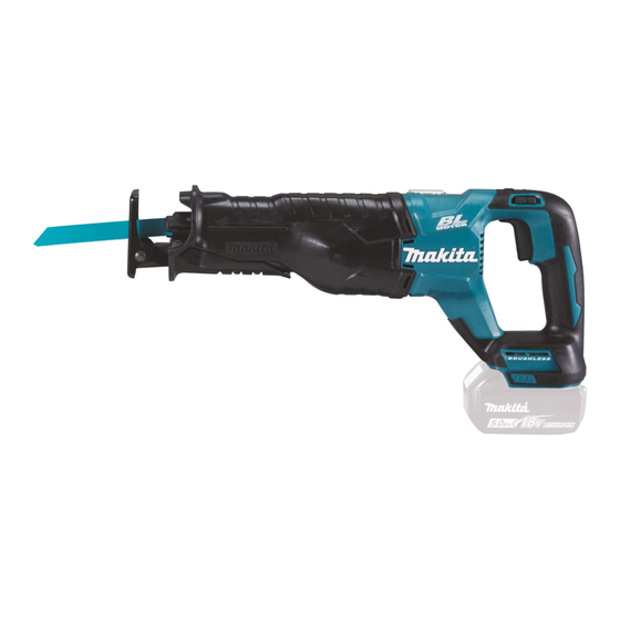
Model DJR187 is a Cordless recipro saw powered by 18V Li-ion battery
and has been developed for higher cutting efficiency and more compact and
lightweight by adopting Vertical crank mechanism and BrushLess DC motor.
Its main features are:
• Ergonomically designed handle
• Toolless shoe adjustment by lever system
• Toolless blade change
• Electric 2 speed for wood/ metal cutting
• Retractable rafter hook
• LED job light with preglow and afterglow functions
Note: BL1815 is not compatible.
S
pecification
Specification
Voltage: V
Capacity: Ah
Battery
Energy capacity: Wh
Cell
Charging time (approx): min
Max output (W)
Strokes per minutes: min
Length of stroke: mm (")
Electric 2 speed
Capacity: mm (")
Blade clamp type
Switch lock function
Electric brake
Variable speed control by trigger
LED job light
Weight according to
EPTA-Procedure 01/ver.2.1: kg (lbs)
*2 When 300mm (11-3/4") blade is used.
*3 With battery BL1815N, BL1820(B)
S
tandard equipment
Recipro saw blade 152mm (6") for wood and metal
Recipro saw blade 200mm (7-7/8") for metal
*4 Battery and Charger and Plastic carrying case are not supplied with "Z" model.
*5 Supplied with the same quantity of extra Battery.
Note: The standard equipment may vary by country or model variation.
O
ptional accessories
Recipro saw blades
Fast charger DC18RC
Charger DC18SD
Charger DC24SC
DJR187
Cordless Recipro Saw
Model
= spm (strokes per minute)
-1
Wood*
2
Pipe: Ø
Automotive charger DC18SE
Two port multi fast charger DC18RD
Four port multi charger DC18SF
1.5, 2.0, 3.0, 4.0, 5.0, 6.0
27, 36, 54, 72, 90, 108
15, 24, 22, 36, 45, 55 with DC18RC
High: 0 - 3,000, Low: 0 - 2,300
130 (5-1/8)
3.4
(7.6)*
Battery*
Battery cover*
4
Charger*
Plastic carrying case*
4
Battery BL1815N
BL1820(B),
BL1830(B), BL1840(B),
BL1850(B), BL1860B
1 / 24
OFFICIAL USE
for ASC & Sales Shop
April 2016
L
W
H
Dimensions: mm ( " )
Length (L)
439 (17-1/4)
Width (W)
83 (3-1/4)
Height (H)
231 (9-1/8)*
*1 With battery
BL1830(B), BL1840(B),
BL1850(B), BL1860B
DJR187
18
Li-ion
670
32 (1-1/4)
Yes
255 (10)
Toolless
Lock-off
Yes
Yes
Yes
or 3.7
(8.2)*
3
1
5
4
1
Advertisement
Troubleshooting

Related Manuals for Makita DJR187


Summary of Contents for Makita DJR187
- Page 1 Cordless Recipro Saw ONCEPT AND MAIN APPLICATIONS Model DJR187 is a Cordless recipro saw powered by 18V Li-ion battery and has been developed for higher cutting efficiency and more compact and lightweight by adopting Vertical crank mechanism and BrushLess DC motor.
-
Page 2: Table Of Contents
NECESSARY REPAIRING TOOLS ............................3 LUBRICANT AND ADHESIVE APPLICATION ........................4 REPAIR ......................................6 Insulation cover ..................................6 5-1-1 Disassembling ................................6 5-1-1-1 For DJR187, DJR360 .............................. 6 5-1-1-2 For DJR186 ................................6 5-1-2 Assembling .................................. 7 Slider assembly ..................................7 5-2-1 Disassembling ................................ -
Page 3: Necessary Repairing Tools
CAUTION Repair the machine in accordance with “Instruction manual” or “Safety instructions”. Follow the instructions described below in advance before repairing: Wear gloves. · Remove the recipro saw blade from the unit. · In order to avoid wrong reassembly, draw or write down where and how the parts are assembled, and what are the parts. ·... -
Page 4: Lubricant And Adhesive Application
Inner surface a little Gear shaft Outer circumference Side surface that contacts Needle bearing Flat washer 4 1012 of Gear complete Makita grease Gear complete Gear portion FANo.2 Flat washer 54 Both side surfaces (front and back) a little (a) Side surfaces that contact Roller... - Page 5 Head point Compression spring 6 Outer circumference Pin 3 Outer circumference Slider guide complete Inner circumference (both sides) a little Makita grease Pin 6 Outer circumference FANo.2 Roller Inner circumference (a) Side surfaces that contact Roller Rod guide R (b) Bottom surface...
-
Page 6: Repair
REPAIR Insulation cover 5-1-1 Disassembling 5-1-1-1 For DJR187, DJR360 Fig. 5-1-1-1-1 Fig. 5-1-1-1-2 [1] Pull Lock lever. [2] Pull out Shoe. [3] Remove Lock lever, and remove Lock pin. Lock pin Shoe Lock lever Lock lever Fig. 5-1-1-1-3 Fig. 5-1-1-1-4 Fig. -
Page 7: Assembling
5-1-2 Assembling Fig. 5-1-2-1 Apply soapy water onto the inner circumference of Insulation cover, and mount Insulation cover to Gear housing assembly by thrusting it. Note: Apply Loctite 272 on M6x14 Hex socket head bolt when you use it again. (Fig. 5-1-1-2-1) Insulation cover Gear housing assembly... - Page 8 Fig. 5-2-1-4 Fig. 5-2-1-5 [5] Twist Sleeve while pulling it up toward the blade install [6] While holding the top of Slider by finger, push out Pin 3 side to set it in release position. with a thin bar. Note: Without holding Slider, Push plate will pop out from the slit of Slider.
- Page 9 5-2-2 Assembling Fig. 5-2-2-1 Fig. 5-2-2-2 [1] Assemble Torsion spring 17 to [2] Set Sleeve by passing the long tail of Torsion spring 17 through the slit of Sleeve by inserting its short tail into Slider. the hole of Sleeve. Sleeve Hole where Pin 3 is...
- Page 10 Fig. 5-2-2-6 Fig. 5-2-2-7 [6] Remove Guide sleeve. [7] Set Driving sleeve to Sleeve while fitting its two projections to the two concaves of Sleeve. Driving sleeve Viewed from the bottom Guide sleeve Projections Concaves of Sleeve Fig. 5-2-2-8 [8] While push Driving sleeve into Gear housing, turn the sleeve clockwise to lock Pin 3 in place. Then, remove Driving sleeve. Driving sleeve Sleeve Pin 3...
- Page 11 Fig. 5-2-2-9 Fig. 5-2-2-10 [9] Mount Driving sleeve guide while aligning its notches [10] Mount Guide sleeve. to the concaves of Sleeve. Guide sleeve Driving sleeve guide Concaves of Sleeve Fig. 5-2-2-11 Fig. 5-2-2-12 [11] Mount Compression spring 6 and Shoulder pin 5 into the [12] Mount Pin 3.
-
Page 12: Rotor Ass'y (Armature Ass'y)
Rotor ass'y (Armature ass'y) 5-3-1 Disassembling 5-3-1-1 For DJR187, DJR360 [1] Remove Insulation cover. (Refer to 5-1 Insulation cover.) Fig. 5-3-1-1-1 [2] Loosen two M5x10 Pan head screws, and remove Hook assembly. M5x10 Pan head screw (2 pcs.) Hook assembly Fig. - Page 13 Fig. 5-3-1-1-5 [6] Loosen four M5x25 Pan head screws, and remove Motor housing section. M5x25 Pan head screw (4 pcs.) Motor housing section Fig. 5-3-1-1-6 [7] Loosen twoM4x16 Pan head screws, and remove Rotor ass'y. Note: If it is hard to remove Rotor ass'y, warm Gear housing L assembly with a heat gun. M4x16 Pan head screw (2 pcs.) Rotor ass'y...
-
Page 14: For Djr186
Fig. 5-3-1-1-9 [10] Remove Ball bearing 607ZZ with 1R269. Ball bearing 607ZZ 1R269 5-3-1-2 For DJR186 [1] Remove Insulation cover. (Refer to 5-1 Insulation cover.) [2] Remove two Brush holders. Fig. 5-3-1-2-1 [3] Loosen four M5x25 Pan head screws, and remove Motor housing section. M5x25 Pan head screw (4 pcs.) Motor housing section... - Page 15 · Magnetic loss of Rotors or damage on the magnet portion of Rotor (Fig. 5-3-2-1-2) · 5-3-2-1 For DJR187, DJR360 Fig. 5-3-2-1-3 Fig. 5-3-2-1-4 [2] Set the U-shaped legs of Bearing retainer 66 into the [3] Check that M5 Square nut is inserted into Motor groove of Gear housing L assembly to assemble housing.
- Page 16 5-3-2-2 For DJR186 Fig. 5-3-2-2-1 Fig. 5-3-2-2-2 [2] Set the U-shaped legs of Bearing retainer 66 into the [3] Align the notch of Yoke unit with the rib of Motor housing, then set Yoke unit in place. groove of Gear housing L assembly to assemble Armature ass'y.
-
Page 17: Gear Complete
Gear complete 5-4-1 Disassembling 5-4-1-1 For DJR187, DJR360 [1] Remove Insulation cover. (Refer to 5-1 Insulation cover.) [2] Remove Rotor ass'y (Armature ass'y). (Refer to 5-3 Rotor ass'y (Armature ass'y).) Fig. 5-4-1-1-1 [3] Loosen twoM4x35 Hex socket head bolts, and remove Shoe guide plate. - Page 18 Fig. 5-4-1-1-5 [7] Remove Gear complete (Spiral bevel gear 47) from Slider. Gear complete (Spiral bevel gear 47) Roller Pin 6 Slider Roller 5-4-1-2 For DJR186 [1] Remove Insulation cover. (Refer to 5-1 Insulation cover.) [2] Remove Rotor ass'y (Armature ass'y). (Refer to 5-3 Rotor ass'y (Armature ass'y).) Fig.
- Page 19 5-4-2 Assembling Fig. 5-4-2-1 Fig. 5-4-2-2 [1] Insert the longer part of Shoulder pin 6-8 into Gear [2] Assemble Felt 16x16 between Slider guide complete housing L assembly. and Gear housing L assembly, and push it in the direction of the arrow. Note: For DJR186 Gear housing L Shoulder pin 6-8...
-
Page 20: Circuit Diagram
Circuit diagram Fig. 6-1 Terminal unit Stator board Closed end splice Switch LED circuit AWG14 Connector Straight receptacle Flag receptacle with with lock (#250, t=0.8) lock (#250, t=0.8mm) Electrolytic Connector Polyolefin tube (inner capacitor diameter: ø5.4mm) Connector Polyolefin tube (inner diameter: AWG14 AWG22... -
Page 21: Wiring Diagram
Wiring diagram Fig. 7-1 Wiring to Gear housing Put LED circuit as shown in the figure. Lens of LED circuit Route the lead wires of LED circuit between the boss A and the rib A. Rib A Boss A Fig. 7-2 Wiring to Motor housing Stator Pass the lead wires of Stator through... - Page 22 Fig. 7-3 Wiring to Handle Put the lead wires of LED circuit between Motor housing and the inner wall B. Rib G Put the lead wires of LED circuit more toward Handle R side than the rib G. Handle L Switch Put the flag receptacle from Switch with its lead...
-
Page 23: Troubleshooting
Troubleshooting Whenever you find any trouble in your machine, first, refer to this list to check the machine for solution. Note in Repairing (1) Use the full charged battery which has the star mark. (2) When Housing is disassembled, check the conditions of the electrical parts (Connectors, Lead wires, Switches, etc.), Rotor, Stator, Gear section, etc. -
Page 24: Flowchart Of Troubleshooting
Flowchart of Troubleshooting Check the items from the top of the following list. (Description of the item is referred to Circuit diagram in Fig. 6-1. After corrective action, return to the start of Troubleshooting and re-check again. Symptom Cause Corrective action Does Tester indicate 0.7V ~ 0.9V? Controller is broken.