Advertisement
Quick Links
T
ECHNICAL INFORMATION
Model No.
Description
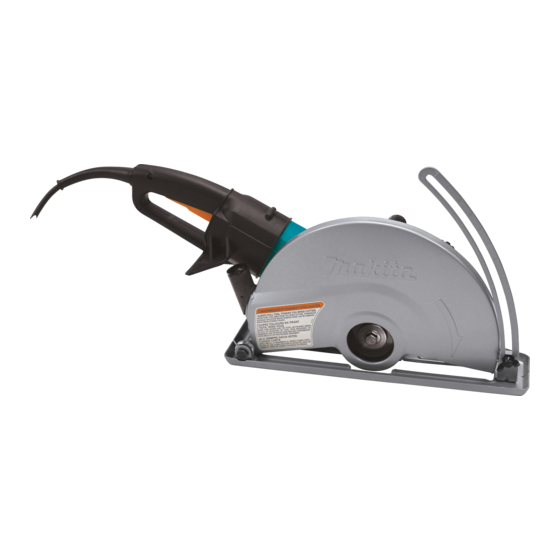
C
ONCEPT AND MAIN APPLICATIONS
Model 4114S is the 355mm (14") version of the current
4112S 305mm (12") Angle cutter, having the following
same benefits as 4112S;
High torque delivered at low motor speed of 3,500rpm
"SJS - Super Joint System" that provides smooth
approach and long service life of gear section
Soft start to minimize startup shock
Model 4114 features the same benefits as 4112S except for
soft start function.
Model 4114 for North American countries feature AC/DC switch.
S
pecification
Model 4114
Voltage (V)
120
Model 4114S
Voltage (V)
110
230
*1: Switzerland =2,300W, Brazil (127V)=1,900W
Specifications
No load speed: min.-
Wheel size: mm (")
Clutch
Soft start
Protection against electric shock
Cord length: m (ft)
Net weight*
: kg (lbs)
2
*2: Without wheel and cord
S
tandard equipment
Socket wrench 17 ................................... 1 pc.
Note: The standard equipment for the tool shown above may differ by country.
O
ptional accessories
Assorted diamond wheels
Assorted abrasive cut off wheels
Base set
Elbow joint 32 (for connecting to vacuum cleaner)
Ring 20
4114, 4114S
Angle Cutter 355mm (14")
Cycle (Hz)
Current (A)
15
AC/ DC
Current (A)
Cycle (Hz)
23
50 / 60
11
50 / 60
Model
= rpm
1
Diameter
Hole diameter
Thickness
Continuous Rating (W)
Input
1,650
Continuous Rating (W)
Input
2,400
2,400*
1
4114
3,500
355 (14)
25.4 (1)
2.6 (1/8)
Yes
(SJS - Super Joint System)
No
Double insulation
2.5 (8.2)
10.8 (23.8)
Dimensions: mm (")
Length (L)
Width (W)
Height (H)
Max. Output (W)
Output
800
Max. Output (W)
Output
1,500
1,600
4114S
Yes
10.9 (24.0)
PRODUCT
P 1 / 6
673 (26-1/2)
240 (9-1/2)
329 (13)
3,000
2,750
3,700
Advertisement

Related Manuals for Makita 4114


Summary of Contents for Makita 4114
- Page 1 "SJS - Super Joint System" that provides smooth approach and long service life of gear section Soft start to minimize startup shock Model 4114 features the same benefits as 4112S except for soft start function. Dimensions: mm (") Model 4114 for North American countries feature AC/DC switch.
-
Page 2: Necessary Repairing Tools
Bearing extractor (Makita Part No.1R269), Retaining ring S and R pliers (Makita Part No.No.1R291), Water pump pliers [2] LUBRICATION Apply Makita grease N. No.1 to the following portions designated by black triangle to protect parts and product from unusual abrasion. Fig.1 The installed part of Spindle complete (Item No. - Page 3 ASSEMBLING 1) Apply Makita grease SG. No.0 to the spring when assembling Lock spring 24 to Spiral bevel gear 57. 2) Tilt and place Lock spring 24 on Spiral bevel gear 57. Press down the portion A (the highest portion) of the spring using arbor press.
- Page 4 1) Remove the Gear section by unscrewing four M5x14 Hex bolts. (Fig. 8) 2) Remove Ball bearing 6000LLB using Ball bearing extractor (Makita Part No.1R269). (Fig. 9) 3) Remove Retaining ring S-15 using Retaining ring S and R pliers (Makita Part No.1R291). Flat washer 15 can now be removed. (Fig. 10) Fig.
-
Page 5: Circuit Diagram
Insulated circuit (If used.) suppressor connector (If used.) iring diagram [1] Wiring in Motor Housing for 4114 and 4114S Connecting lead wire (purple) Hook from Brush holder Route the following lead wires through the hook: * Field lead wire (black) - Page 6 P 6 / 6 iring diagram [2] Wiring in Handle for 4114 Fix the following lead wires Put Noise suppressor with this lead wire holder: in this space if used. Switch *2 Field lead wires (black) *Lead wire of Soft start circuit (white)