Makita LS1040F Technical Information
Hide thumbs
Also See for LS1040F:
- Instructions manual (104 pages) ,
- Instruction manual (89 pages) ,
- Parts breakdown (4 pages)
Advertisement
Quick Links
T
ECHNICAL INFORMATION
Models No.
Description
C
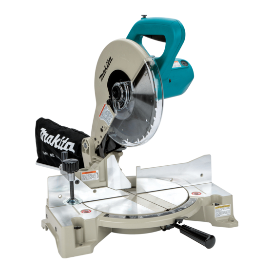
ONCEPTION AND MAIN APPLICATIONS
Model LS1040F is advanced version of Model LS1040.
Maintain all the advantage of LS1040, plus fluorescent lamp
with inverter (Light up wide range and easy to watch
the cutting line in dimly-lit place.)
It's brief benefits are
*Higher rigidity of all over the body
*More accurate cut
*Bevel cut (left only)
*More efficient chip/sawdust collection
*More stable cutting by holding material
more widely with sub fence
S
pecification
Voltage (V)
110
120
220
230
240
Diameter : mm (")
Blade
Arbor : mm (")
No load speed (min
Protection from electric shock
Electric brake
Lock off switch
Cord length : m (ft)
Net weight : Kg (lbs)
Bevel angle
Miter angle
0°
45°
(left and right)
S
tandard equipment
* Dust Bag Ass' y ---------------1 pc.
* Triangular Rule---------------- 1pc.
* Socket Wrench 13------------- 1 pc.
< Note > The standard equipment for the tool shown may differ from country to country.
O
ptional accessories
* Vise Ass'y (Horizontal Vise)
* Crown molding stopper set
* Various T.C.T. saw blades
LS1040F
Miter saw 255mm (10")
Cycle (Hz)
Current (A)
15
50 / 60
15
50 / 60
7.9
50 / 60
7.5
50 / 60
50 / 60
7.2
= rpm)
-1
Capacity with : mm (") * The equipped saw blade : 255mm (10') in diameter
0°
90.5 x 95
(5-9/16 x 3-3/4)
69 x 130
(2-3/4 x 5-1/8)
90.5 x 67
(5-9/16 x 2-5/8)
69 x 92
(2-3/4 x 3-5/8)
* Switch Button (as a spare) ----2 pcs.
* Sub Plate Assembly ---------1 pc.
* Holder 255 --------------------2 pcs.
* Ring 15.88 for the saw blade with arbor, 25.4mm
* Ring 16 for the saw blade with arbor, 25mm
* Ring 16 for the saw blade with arbor, 30mm
Dimensions : mm ( " )
Length ( L )
476 (18-3/4)
Height ( H )
532 (21)
Width ( W )
* 530 (20-7/8)
Continuous Rating (W)
Input
1,650
1,650
1,650
1,650
1,650
255 (10) - 260 (10-1/4)
15.88 (5/8) for North America,
30mm (1-3/16) for Europe
by double insulation
Yes (only for high voltage area)
Yes
2.0 m (6.5) for Australia
11.6 (25.5)
45°
(left)
48 x 95
(1-7/8 x 3-3/4)
35 x 130
(1-3/8 x 5-1/8)
48 x 67
(1-7/8 x 2-5/8)
35 x 92
(1-3/8 x 3-5/8)
W
* from grip 32 to lever 100
Max. Output(W)
Output
1,000
1,000
1,000
1,000
1,000
25.4mm (1) for Others
4,600
2.5 m (8.2) for others
* Vise Ass'y (Vertical Vise)----1 pc.
* T.C.T. Saw Blade 255--------1 pc.
* Holder set
* Set plate
* Fluorescent tube
PRODUCT
P 1 / 8
H
L
2,300
2,300
2,300
2,300
2,300
Advertisement

Related Manuals for Makita LS1040F


Summary of Contents for Makita LS1040F
- Page 1 Description Miter saw 255mm (10") ONCEPTION AND MAIN APPLICATIONS Model LS1040F is advanced version of Model LS1040. Maintain all the advantage of LS1040, plus fluorescent lamp with inverter (Light up wide range and easy to watch the cutting line in dimly-lit place.)
- Page 2 < Note > Take off saw blade from the machine for your safety, before repairing or maintenance ! < 1 > Lubrication Apply MAKITA grease N. No.1 to the following portions marked with black triangle to protect parts and product from unusual abrasion.
- Page 3 P 3 / 8 epair < 2 > Removing compression spring 28 and motor unit 1) Holding the motor unit at the lowest position, insert 2 pcs. of bars into the side holes of blade case. See Fig. 1. ( The size of bars are 125 - 130mm in length and 4 - 6.5mm in diameter as illustrated in Fig. 1A.) So, compression spring 28 and spring holder cannot spring out of blade case, when separating blade case from arm.
- Page 4 P 4 / 8 epair 4) Put the block between the inserted 2 bars. And set the separated motor unit on the turn base of arbor press. as illustrated in Fig. 4. 5) Pressing the block with arbor press, take off the 2 bars. See Fig. 5. Block Fig.
- Page 5 P 5 / 8 epair (3) Mount the motor unit to arm aligning the arm's holes with blade cases holes for inserting rod 16. See Fig. 11. Link plate Fig. 11 (4) Insert rod 16 which works as an axis for swinging motor unit. See Fig. 12. And fasten rod 16 with hex socket head bolt M6x10.
- Page 6 < 4 > Mounting slide plates Aligning with the circle portion (on which turn base slides.) of base, mount slide plates as illustrated in Fig. 15. And then, apply MAKITA grease N. No.1 to the slide plates. Slide plates Fig. 15 <...
-
Page 7: Circuit Diagram
P 7 / 8 ircuit diagram For low voltage Color index of lead wires Black White Field (view from armature fan side) Yellow Orange Switch Field Terminal (view from commutator side) Noise block suppressor * For some countries, the products can be supplied without installing terminal block and noise suppressor . -
Page 8: Wiring Diagram
P 8 / 8 iring diagram <Note> For some countries, the products can be supplied without installing terminal block soft starter circuit, choke coil and noise suppressor . The receptacles connected to switch for brake, have to be faced Lead wires of light assembly to the wall of handle.