Honeywell 7800 SERIES Instruction Manual
Relay modules
Hide thumbs
Also See for 7800 SERIES:
- Product data (64 pages) ,
- Manual (56 pages) ,
- Installation instructions manual (40 pages)
Advertisement
Table of Contents
- 1 Installation
- 2 Mounting Wiring Subbase
- 3 Wiring Subbase
- 4 Final Wiring Check
- 5 Static Checkout
- 6 Equipment Recommended
- 7 General Instructions
- 8 Mounting Other System Components (Fig. 5)
- 9 Principal Technical Features
- 10 Sequence of Operation
- 11 Settings and Adjustments
- 12 Selectable Site-Configurable Jumpers
- 13 Flame Signal Measurement
- Download this manual
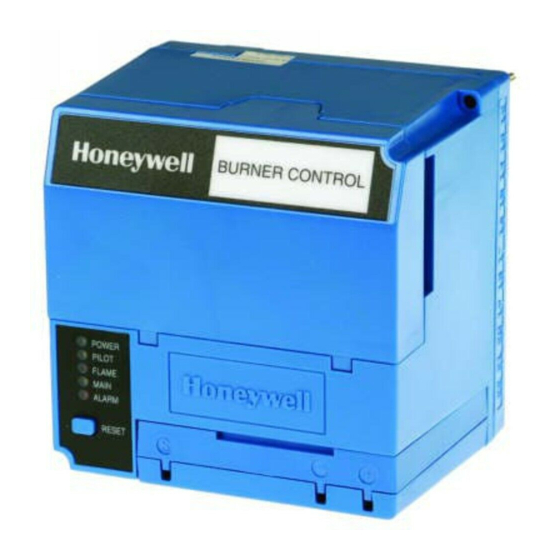
EC7830A, RM7830A, EC7850A,
RM7850A
7800 SERIES Relay Modules
APPLICATION
The Honeywell EC/RM7830A and EC/RM7850A are
microprocessor-based integrated burner controls for
automatically fired gas, oil, or combination fuel single burner
full modulation (EC/RM7850A) or on/off (EC/RM7830A)
applications. The EC/RM7830A; EC/RM7850A system
consists of a relay module, subbase, amplifier, and purge
card. Options include keyboard display module (KDM),
Personal Computer Interface, Data ControlBus™ Module,
remote display mounting and Combustion System Manager
Software.
Functions provided by the EC/RM7830A and EC/RM7850A
include automatic burner sequencing, flame supervision,
system status indication, system or self-diagnostics and
troubleshooting. Text readout on the Keyboard Display
Module is available in English, Spanish, Portuguese,
Katakana (Japanese), French, German, and Italian
languages.
This document provides installation and static checkout
instructions. Other applicable publications are:
63-2278:Q7700 Network Interface Unit Product Data.
65-0084:Q7800A,B 22-Terminal Wiring Subbase
Product Data.
65-0090:S7800A Keyboard Display Module Product Data.
65-0091:S7810A Data ControlBus™ Module Product Data.
65-0095:S7820 Remote Reset Module Product Data.
65-0097:221729C Dust Cover Packing Instructions.
65-0102:ZM7850A Combustion System Manager
Operating Instructions.
65-0109:R7824, R7847, R7848, R7849, R7861, R7886 Flame
Amplifiers for the 7800 SERIES Product Data.
65-0131:221818A Extension Cable Assembly Product Data.
65-0228:S7810B Multi-Drop Switch Module Product Data.
65-0229:7800 SERIES Relay Modules Checkout and
Troubleshooting Product Data.
65-0249:S7810M ModBus Network Protocol.
honeyvell.energy
SPECIFICATIONS
Electrical Ratings (See Tables 3A, 3B, 3C and 3D):
Voltage and Frequency:
RM7830A and RM7850A:
EC7830A and EC7850A:
Power Dissipation: 10W maximum.
Maximum Total Connected Load: 2000 VA.
®
Fusing Total Connected Load: 15A maximum, Fast Blow, type
SC or equivalent.
Environmental Ratings:
Ambient Temperature:
Operating: -40°F to 140°F (-40°C to +60°C).
Storage: -40°F to 150°F (-40°C to +66°C).
Humidity: 85% relative humidity continuous, noncondensing.
Vibration: 0.5G environment.
SIL 3 Capable:
SIL 3 Capable in a properly designed Safety Instrumented
System. See form 65-0312 for Certificate Agreement
Approvals:
RM7830A and RM7850A:
Factory Mutual Approved: Report No. J.I.1V9A0.AF.
Swiss Re (formerly Industrial Risk Insurers): Acceptable.
Federal Communications Commission: Part 15,
EC7830A and EC7850A: Factory Mutual Approved.
These products also comply with the following European
®
directives:
Gas Appliance Directive: 90/396/EEC.
Low Voltage Directive: 73/23/EEC.
EMC Directive: 89/336/EEC.
GASTEC: CE-63AP3070/1.
Lloyds Register Approval.
Oil appliances:
EC7830A: DIN-5F 106/96.
EC7850A: DIN-5F 107/96.
These products are approved according to EN298, "Automatic
gas burner systems for gas burners and gas burning
appliances with or without fans."
Please note the following to comply with EN60730 for remote
mounting of the KDM and/or remote reset module. It is
necessary to provide electrical separation using insulation at
SIL
Capable
INSTALLATION INSTRUCTIONS
120 Vac (+10/-15%), 50/60 Hz (±10%).
220/240 Vac (+10%/-15%), 50/60 Hz (±10%)
Class B, Emissions.
3
66-1092-06
Advertisement
Table of Contents

Related Manuals for Honeywell 7800 SERIES


Summary of Contents for Honeywell 7800 SERIES
- Page 1 Operating Instructions. Gas Appliance Directive: 90/396/EEC. Low Voltage Directive: 73/23/EEC. 65-0109:R7824, R7847, R7848, R7849, R7861, R7886 Flame EMC Directive: 89/336/EEC. Amplifiers for the 7800 SERIES Product Data. GASTEC: CE-63AP3070/1. 65-0131:221818A Extension Cable Assembly Product Data. Lloyds Register Approval. Oil appliances: 65-0228:S7810B Multi-Drop Switch Module Product Data.
-
Page 2: Installation
EC7830A, RM7830A, EC7850A, RM7850A 7800 SERIES RELAY MODULES least equivalent to double or reinforced insulation. This can be IMPORTANT accomplished by either: 1. Wiring connections for the relay modules are unique; 1. Optically isolating the communication and/or remote refer to Fig. 3 and 4 or the appropriate Specifications for reset lines from the control cabinet or individual subbase wiring. -
Page 3: Wiring Subbase
EC7830A, RM7830A, EC7850A, RM7850A 7800 SERIES RELAY MODULES Wiring Subbase c. Enclose flame detector leadwires without armor cable in metal cable or conduit. d. Follow directions in flame detector, Data Control- WARNING Bus™ Module, or Remote Reset Module Instruc- tions. - Page 4 EC7830A, RM7830A, EC7850A, RM7850A 7800 SERIES RELAY MODULES HOT N PLUG-IN PURGE CONFIGURATION TIMER CARD JUMPERS TEST JACK FLAME SIGNAL RUN/TEST SWITCH PLUG-IN MICROCOMPUTER FLAME RESET AMPLIFIER PUSHBUTTON SHUTTER RELAY DRIVE CIRCUIT RELAY STATUS FEEDBACK AND LINE VOLTAGE INPUTS SAFETY RELAY...
- Page 5 EC7830A, RM7830A, EC7850A, RM7850A 7800 SERIES RELAY MODULES HOT N PLUG-IN PURGE CONFIGURATION TIMER CARD JUMPERS TEST FLAME SIGNAL JACK RUN/TEST SWITCH PLUG-IN MICROCOMPUTER FLAME AMPLIFIER RESET SHUTTER PUSHBUTTON RELAY DRIVE CIRCUIT RELAY STATUS FEEDBACK AND LINE VOLTAGE INPUTS SAFETY RELAY...
- Page 6 EC7830A, RM7830A, EC7850A, RM7850A 7800 SERIES RELAY MODULES Q7800 LEGEND ALARM (NORMALLY OPEN) PREIGNITION INTERLOCK INPUT BURNER/BLOWER MOTOR IGNITION LINE VOLTAGE SUPPLY (L1) LOCKOUT INPUT AIRFLOW SWITCH INPUT MAIN FUEL VALVE PILOT VALVE 1 (INTERRUPTED) PILOT VALVE 2 (INTERMITTENT) LIMITS AND BURNER...
- Page 7 EC7830A, RM7830A, EC7850A, RM7850A 7800 SERIES RELAY MODULES LEGEND SERIES 90 SERIES 90 FIRING RATE ALARM CONTROLLER Q7800 MOTOR (NORMALLY OPEN) HIGH FIRE LOW FIRE SWITCH INPUT COMMON PREIGNITION INTERLOCK INPUT MODULATE HIGH FIRE SWITCH INPUT LOW FIRE BURNER/BLOWER (L1)
-
Page 8: Final Wiring Check
EC7830A, RM7830A, EC7850A, RM7850A 7800 SERIES RELAY MODULES Fig. 4. Wiring subbase and sequence chart for EC/RM7850A. Table 1. Recommended Wire Sizes and Part Numbers. Application Recommended Wire Size Recommended Part Numbers Line Voltage Terminals 14, 16, or 18 AWG copper conductor, 600 volt TTW60C, THW75C, THHN90C. - Page 9 See Table 2. Honeywell has tested this output at 9.8A at PF = 0.5, 58.8A inrush for 100,000 cycles (EN298 approval does not require this test). 2000 VA maximum connected load to relay module.
- Page 10 See Table 2. 2000 VA maximum connected load to relay module. Honeywell has tested this output at 9.8A at PF = 0.5, 58.8A inrush for 100,000 cycles (EN298 approval does not require this test). Total load current, excluding Burner/Boiler Motor and Firing Rate Outputs cannot exceed 5A, 25A inrush.
-
Page 11: Equipment Recommended
EC7830A, RM7830A, EC7850A, RM7850A 7800 SERIES RELAY MODULES Equipment Recommended WARNING Voltmeter (1M ohm/volt minimum sensitivity) set on the 0 to Electrical Shock Hazard. 300 Vac scale and two jumper wires, No. 14 wire, insulated, Can cause severe injury, death, or property 12 in. - Page 12 EC7830A, RM7830A, EC7850A, RM7850A 7800 SERIES RELAY MODULES Table 5. EC/RM7830A Static Checkout. (Continued) Test Test If Operation is Abnormal, Check the Items Jumpers Voltmeter Normal Operation Listed Below — 1. Ignition spark (if ignition transformer 1. Watch for spark or listen for buzz.
-
Page 13: Mounting Other System Components (Fig. 5)
EC7830A, RM7830A, EC7850A, RM7850A 7800 SERIES RELAY MODULES Table 6. EC/RM7850A Static Checkout. (Continued) Test Test Jumpers Voltmeter Normal Operation If Operation is Abnormal, Check These Items 4-21 — Same test as no. 4 for connections to Same as test no. 4. If using direct spark ignition, terminal 8. -
Page 14: Sequence Of Operation
EC7830A, RM7830A, EC7850A, RM7850A 7800 SERIES RELAY MODULES d. Low Fire Switch fails to close within five minutes, 8. RUN Period. after firing rate motor is commanded to drive to low a. No flame is present. fire position at end of purge (EC/RM7850A). -
Page 15: Settings And Adjustments
EC7830A, RM7830A, EC7850A, RM7850A 7800 SERIES RELAY MODULES Postpurge 1. The Preignition Interlocks, Limits and Burner Control, Run/Test Switch, Airflow Switch Input, Lockout Input, The relay module (model specific) provides a two-, 15- or and all microcomputer-monitored circuits must also be 30-second POSTPURGE following the completion of the RUN in the correct operating state. -
Page 16: Flame Signal Measurement
EC7830A, RM7830A, EC7850A, RM7850A 7800 SERIES RELAY MODULES changed after the 200 hours occur, the relay module locks out. If JR3 (Airflow Switch) is intact (no Airflow Switch), then a This safety function assures that the relay module cannot be jumper must be installed between terminals 6 and 7.