Advertisement
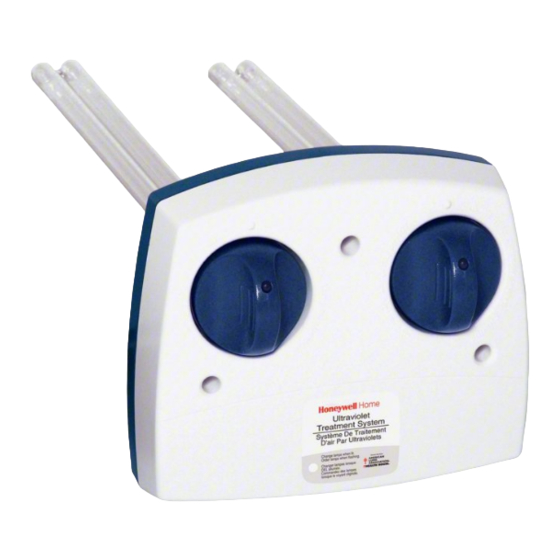
UV100E Ultraviolet Systems
UV100E1043 AND UV100E2009 AIR TREATMENT SYSTEMS
UV100E3007 SURFACE TREATMENT SYSTEM
APPLICATION
When installed in forced air heating and cooling systems, the
UV100E Ultraviolet Systems kill airborne or surface micro-
organism contaminants like mold and bacteria.
The UV systems use patented SmartLamp™ control
technology that monitors the HVAC system to operate the
lamps only when needed. This technology extends bulb life up
to five times and reduces power consumption, lowering
operating costs. The UV systems also include local
diagnostics with the SmartLamp™ LED and reset capability.
FEATURES
• SnapLamp™ features replacement lamp handle with
detachable replacement bulb, UC18W or UC36W, to
make replacement more economical.
• SmartLamp™ Control Algorithm determines optimal
UV lamp usage.
• SmartLamp™ LED shows bulb life and replacement.
• Reduced power consumption and extended bulb life.
• Communicates with other home appliances through
Enviracom™ three-wire communications bus.
• Automatic brownout and high temperature protection
for UV lamps.
• Return air models supplied with integrated airflow
sensor to monitor air flowing through ductwork.
• Dual-purpose reset button:
- Commands lamp on with a single one-second
push.
- Resets internal lamp run-time timer after bulb
replacement with extended five-second hold.
• UV-C light kills airborne bacteria and surface mold.
• UV lamp does not produce ozone.
• Easy lamp maintenance with quick, easy bulb
replacement.
• Sealed unit prevents accidental installer/homeowner
contact with high voltage and ultraviolet rays.
• Safe design prevents lamp from lighting unless base is
correctly mounted on HVAC duct.
• Lamp light indicator to safely view lamp operation.
• Power cord that plugs into 120 Vac electrical outlet.
• Five-year limited warranty.
Application/Features .........................................................
Specification/Ordering Information ...................................
Installation ........................................................................
Checkout ..........................................................................
Troubleshooting and Service/Maintenance ......................
Parts List .......................................................................... 11
PRODUCT DATA
Contents
1
2
3
7
8
68-0262-5
Advertisement

Related Manuals for Honeywell UV100E series


Summary of Contents for Honeywell UV100E series
-
Page 1: Table Of Contents
UV100E Ultraviolet Systems UV100E1043 AND UV100E2009 AIR TREATMENT SYSTEMS UV100E3007 SURFACE TREATMENT SYSTEM PRODUCT DATA FEATURES • SnapLamp™ features replacement lamp handle with detachable replacement bulb, UC18W or UC36W, to make replacement more economical. • SmartLamp™ Control Algorithm determines optimal UV lamp usage. -
Page 2: Specification/Ordering Information
If you have additional questions, need further information, or would like to comment on our products or services, please write or phone: 1. Your local Honeywell Automation and Control Products Sales Office (check white pages of your phone directory). 2. Honeywell Customer Care... -
Page 3: Installation
UV100E ULTRAVIOLET SYSTEMS Selecting Mounting Location Temperature Ratings: Ambient Temperature Range: 30°F to 104°F (-2°C to 40°C). Bulb Temperature Range (In Moving Air): 30°F to 140°F (-2°C to 60°C). Relative Humidity: CAUTION Up to 95% rh, non-condensing. Equipment Damage Hazard. Dimensions: Ultraviolet light can cause color shift or structural See Fig. - Page 4 UV exposure white paper, form no. sensor. 50-8788, at hbctechlit.honeywell.com Web site. 9. Install unit into duct using three (or two, depending on model) no.10, 2 in. Phillips head sheet metal mounting screws provided.
- Page 5 UV100E ULTRAVIOLET SYSTEMS SURFACE TREATMENT SYSTEM 3-1/2 (89) (25) (178) 2-1/4 (57) 14-7/8 (379) 4 (102) 3-1/2 (89) 4-1/2 (114) M20190A 7 (178) AIR TREATMENT SYSTEM (SINGLE LAMP) 3-1/2 (89) (25) (178) 2-1/4 (57) 4 (102) 1/2 (12) 7-7/16 (188) 3-1/2 (89) 4-1/2 (114) M20191A...
- Page 6 UV100E ULTRAVIOLET SYSTEMS 13. Rotate the lamp handle clockwise until it snaps into place CAUTION with the lamp light indicator aligned with the raised button on the unit cover. See Fig. 6. Breakable Glass Hazard. Can cause personal injury. Be careful when inserting bulb(s) into lamp base. Wear protective gloves when handling bulb(s).
-
Page 7: Checkout
UV100E ULTRAVIOLET SYSTEMS 16. For air treatment systems, wait ten minutes for the The installer should orient the homeowner to the unit by airflow sensor to calibrate. During this time, the furnace showing them the blue glow of the lamp light indicator and fan must remain off. -
Page 8: Troubleshooting And Service/Maintenance
UV100E ULTRAVIOLET SYSTEMS TROUBLESHOOTING AND SERVICE Quarterly Bulb Cleaning The Ultraviolet System has no field-serviceable parts. Bulb cleaning is recommended as routine maintenance quarterly or every three months. Bulb replacement is required when the LED on the front of the UV system is lighted solidly. See the MERCURY NOTICE Owner’s Guide for detailed procedural information. - Page 9 UV100E ULTRAVIOLET SYSTEMS 7. Insert the lamp handle into the base with the lamp light indicator at the eleven o’clock position. Continue pushing and gently rotating counterclockwise until the lamp handle inserts fully into the base. See Fig. 14. M22847 M22841 Fig.
- Page 10 UV100E ULTRAVIOLET SYSTEMS 10. For Air Treatment Systems, wait ten minutes for the airflow sensor to calibrate. During this time, the furnace fan must remain off. NOTE: Failure to wait ten minutes for the airflow sensor to calibrate before powering the system fan causes the airflow sensor to incorrectly calibrate and the device M22851 to incorrectly function.
-
Page 11: Parts List
UV100E ULTRAVIOLET SYSTEMS PARTS LIST Replacement Bulb/Handle Replacement Assembly Bulb System Description UV100E1043 UC100E1006 UC18W1004 Air Treatment System (single-lamp) (left photo) UV100E3007 Surface UC100E1030 UC36W1006 Treatment System (center photo) UV100E2009 Air UC100E1030 UC36W1006 Treatment System (two required) (two required) (dual lamp) (right photo) M18621B 68-0262—5... - Page 12 UV100E ULTRAVIOLET SYSTEMS ALIGN EITHER OF THESE LINES AS CLOSE AS POSSIBLE TO DUCT CENTER LINE CENTER OF 2 IN. (51 MM) HOLE FOR LAMP 3/32 IN. (3 MM) PILOT HOLES FOR MOUNTING SCREWS 1-1/2 IN. (38) HOLE FOR AIRFLOW SENSOR CENTER OF AIRFLOW SENSOR HOLE M20194A...
- Page 13 UV100E ULTRAVIOLET SYSTEMS 68-0262—5...
- Page 14 UV100E ULTRAVIOLET SYSTEMS ALIGN EITHER OF THESE LINES AS CLOSE AS POSSIBLE TO DUCT CENTER LINE CENTER OF 2 IN. (51 MM) HOLE FOR LAMP 3/32 IN. (3 MM) PILOT HOLES FOR MOUNTING SCREWS INSTALLATION TEMPLATE FOR SURFACE TREATMENT SYSTEM M20193A Fig.
- Page 15 UV100E ULTRAVIOLET SYSTEMS 68-0262—5...
- Page 16 UV100E ULTRAVIOLET SYSTEMS Automation and Control Solutions Honeywell International Inc. Honeywell Limited-Honeywell Limitée 1985 Douglas Drive North 35 Dynamic Drive Golden Valley, MN 55422 Toronto, Ontario M1V 4Z9 customer.honeywell.com ® U.S. Registered Trademark © 2007 Honeywell International Inc. 68-0262—5 M.S. Rev. 03-07...