Advertisement
Quick Links
T
ECHNICAL INFORMATION
Model No.
Description
C
ONCEPT AND MAIN APPLICATIONS
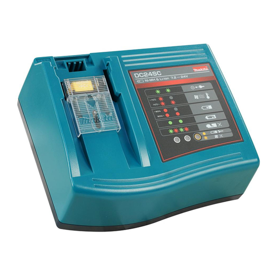
DC24SC is able to charge 7.2V up to 24V Ni-MH/ Li-ion batteries
of slide-type using the unique Optimum Charging System for extended
battery life.
With Interchangeable adapter ADP04 attached, the chargeable range
can be extended further to the following insert-type batteries:
7.2V-18V Ni-Cd batteries (both stick and cluster types)
7.2V-18V Ni-MH batteries (both stick and cluster types)
S
pecification
Voltage (V)
110 - 120
220 - 240
DC Output voltage
Charging time (approx.): min.
[See *
for the model name
1
of each battery.]
Protection from electric shock
Power supply cord: m (ft )
Net weight: kg (lbs)
*
Ni-MH 1.7Ah, 9.6V: B9017A
1
Ni-MH 2.0Ah, 9.6V/12V/14.4V: BH9020, BH9020A, BH1220, BH1220C, BH1420
Ni-MH 2.7Ah, 14.4V: BH1427
Ni-MH 3.3Ah, 9.6V/12V/14.4V: BH9033, BH9033A, BH1233, BH1233C, BH1433
Ni-MH 1.7Ah/2.0Ah, 24V: B2417, BH2420
Ni-MH 3.0Ah/3.3Ah, 24V: B2430, BH2433
Li-ion 1.5Ah, 14.4V/18V: BL1415, BL1815
Li-ion 3.0Ah, 14.4V: BL1430, BL1430A
Li-ion 3.0Ah, 18V: BL1830
*
excludes some countries.
2
O
ptional accessories
Interchangeable adapter ADP01
Interchangeable adapter ADP04
Refreshing adapter ADP02
Automatic refreshing adapter ADP03
DC24SC
Charger
Cycle (Hz)
Current (A)
---
50/ 60
---
50/ 60
Voltage: V
Amperage: A
1.7Ah
2.0Ah
2.7Ah
Ni-MH
3.3Ah
1.7Ah/ 2.0Ah
3.0Ah/ 3.3Ah
1.5Ah
Li-ion
3.0Ah
3.0Ah
H
Length (L)
Width (W)
Height (H)
Continuous Rating (W)
Input
Output
145
145
9.6V
9.6V/ 12V/ 14.4V
14.4V
9.6V/ 12V/ 14.4V
24V
24V
14.4V/ 18V
14.4V
18V
PRODUCT
L
W
Dimensions: mm (")
175 (6-7/8)
215 (8-1/2)
110 (4-5/16)
Max. Output (W)
---
---
---
---
7.2 - 24
6 - 3.6
20
25
30
50
20
30
35
Double insulation*
2
2.0 (6.6)
1.3 (2.8)
P 1/ 5
Advertisement

Related Manuals for Makita DC24SC


Summary of Contents for Makita DC24SC
- Page 1 DC24SC Description Charger ONCEPT AND MAIN APPLICATIONS DC24SC is able to charge 7.2V up to 24V Ni-MH/ Li-ion batteries of slide-type using the unique Optimum Charging System for extended battery life. With Interchangeable adapter ADP04 attached, the chargeable range can be extended further to the following insert-type batteries: 7.2V-18V Ni-Cd batteries (both stick and cluster types)
-
Page 2: Terminal Unit
P 2/ 5 epair CAUTION: Disconnect the machine for safety before repair/ maintenance in accordance with the instruction manual! [3] DISASSEMBLY/ASSEMBLY Note: Be careful not to confuse the following two Compression springs because they are not interchangeable: Compression spring 4 (233194-8) assembled to Charger case cover Compression spring 4 (231474-6) assembled to Terminal cover [3]-1. -
Page 3: Terminal Cover
P 3/ 5 epair [3] DISASSEMBLY/ASSEMBLY [3]-2. Terminal Unit ASSEMBLING Assemble Terminal unit to Charger case cover as described in Fig. 3. Fig. 3 1. Slide Compression spring 4 (233194-8) over the pin of 2. Insert three legs of Terminal unit into the Charger case cover until it stops against the rib. - Page 4 P 4/ 5 epair [3] DISASSEMBLY/ASSEMBLY [3]-3. Terminal Cover ASSEMBLING Assemble Terminal cover to Charger case as described in Fig. 5. Fig. 5 1. Set Compression spring 4 (231474-6/ 2 pcs) in place on the back of Terminal cover as illustrated below. Terminal cover Compression spring 4 (231474-6/ 2 pcs)
-
Page 5: Wiring Diagram
P 5/ 5 epair [3] DISASSEMBLY/ASSEMBLY [3]-4. Varistor and Fuse Cause of Breakage: Varistor is broken when Charging circuit is continuously loaded with very high voltage; for example, when Charger is plugged in a power source at double the rated voltage. In this case, Fuse will also be blown up to protect Charging circuit. Sign of Breakage: Cracks and/or black discoloration on the surface of Varistor, melt-down Fuse What to Do for Repair:...