
Related Manuals for Honeywell SmartDrive Compact


Summary of Contents for Honeywell SmartDrive Compact
- Page 1 Honeywell Complete User Manual SmartDrive Compact Constan and variable torque Variable Frequency Drives for Induction motors Subject to changes without notice...
-
Page 2: Table Of Contents
6. SMARTDRIVE COMPACT CONTROL CONNECTIONS ....25 6.1 Introduction................25 6.2 Control I/O ................26 7. CONTROL PANEL................27 7.1 General...................27 7.2 Display..................27 7.3 Keypad ...................28 7.4 Navigation on the SmartDrive Compact control panel ...29 7.4.1 Main menu ..............29 7.4.2 Reference menu ............30 7.4.3 Monitoring menu ............30... - Page 3 9.12.1 Modbus process data ..........67 10. TECHNICAL DATA ...............70 10.1 SmartDrive Compact technical data ........70 10.2 Power ratings................72 10.2.1 SmartDrive Compact - Mains voltage 208 - 240 V ..72 10.2.2 SmartDrive Compact - Mains voltage 380 - 480 V ..73...
-
Page 4: Safety
1.1 WARNINGS The components of the power unit of the inverter are live when SmartDrive Compact is connected to mains potential. Coming into contact with this voltage is extremely dangerous and may cause death or severe injury. The control unit is isolated from the mains potential. - Page 5 Safety Honeywell If SmartDrive Compact is disconnected from mains while running the motor, it remains live if the motor is energized by the process. In this case the motor functions as a generator feeding energy to the inverter. After disconnecting the inverter from the mains, wait until the fan stops and the indicators on the display go out.
-
Page 6: Safety Instructions
If the cover of SmartDrive Compact is opened, warranty becomes void. 1.3 GROUNDING AND EARTH FAULT PROTECTION The SmartDrive Compact inverter must always be earthed with an grounding con- ductor connected to the grounding terminal. See figure below: •... -
Page 7: Before Running The Motor
Safety Honeywell 1.4 BEFORE RUNNING THE MOTOR Checklist: Before starting the motor, check that the motor is mounted properly and ensure that the machine connected to the motor allows the motor to be started. Set the maximum motor speed (frequency) according to the motor and the machine connected to it. -
Page 8: Receipt Of Delivery
2.2 STORAGE If the inverter is to be kept in store before use make sure that the ambient conditions are acceptable: Storing temperature-40…+70°C Relative humidity < 95%, no condensation MAINTENANCE In normal operating conditions, SmartDrive Compact inverters are maintenance- free. -
Page 9: Warranty
Receipt of Delivery Honeywell WARRANTY Honeywell’s time of warranty is 30 months from the delivery or 24 months from the commissioning whichever expires first (General Conditions NL92/Orgalime S92 ). -
Page 10: Installation
Honeywell 3. INSTALLATION 3.1 MECHANICAL INSTALLATION There are two possible ways to mount SmartDrive Compact in the wall; either screw or DIN-rail mounting. The mounting dimensions are given on the back of the drive and on the following page. MI2-3... -
Page 11: Smartdrive Compact Dimensions
Table 3.1 : SmartDrive Compact dimensions in millimetres 3.1.2 Cooling Forced air flow cooling is used in all SmartDrive Compact drives. Enough free space shall be left above and below the inverter to ensure sufficient air circulation and cooling. You will find the required dimensions for free space in the ta-... -
Page 12: Emc-Levels
(see below). The EMC class of each product is defined in the type designation code. Category C1 (Honeywell EMC class C): Inverters of this class comply with the re- quirements of category C1 of the product standard EN 61800-3 (2004). Category C1... -
Page 13: Changing The Emc Protection Class
Installation Honeywell IT networks (Honeywell EMC class T): Inverters of this class fulfil the product standard EN 61800-3 (2004) if intended to be used in IT systems. In IT systems, the networks are isolated from earth, or connected to earth through high impedance to achieve a low leakage current. -
Page 14: Cabling And Connections
Installation Honeywell 3.2 CABLING AND CONNECTIONS 3.2.1 Power cabling Note! Tightening torque for power cables is 0.5 - 0.6 Nm Figure 3.4: SmartDrive Compact power connections, MI1 Figure 3.5: SmartDrive Compact power connections, MI2 - MI3... -
Page 15: Control Cabling
Installation Honeywell 3.2.2 Control cabling Figure 3.6: Mount the PE- plate and control cable support... - Page 16 Installation Honeywell Figure 3.7: Open the cover Control cable tightening torque: 0.4 Nm Strip the plastic cable coating for 360° grounding Figure 3.8: Install the control cables. See Chapter 6.2...
-
Page 17: Cable And Fuse Specifications
Frame Type terminal terminal terminal terminal Cu [mm P25-P75 1.7-3.7 2*1.5+1.5 1.5-4 1.5-4 0.5-1.5 0.5-1.5 1P1-1P5 4.8-7.0 2*2.5+2.5 1.5-4 1.5-4 0.5-1.5 0.5-1.5 2*6+6 1.5-6 1.5-6 0.5-1.5 0.5-1.5 Table 3.6 : Cable and fuse sizes for SmartDrive Compact, 208 - 240V... -
Page 18: General Cabling Rules
1.5-6 0.5-1.5 0.5-1.5 Table 3.7 : Cable and fuse sizes for SmartDrive Compact, 380 - 480V Note! To fulfil standard EN61800-5-1, the protective conductor should be at least 10mm Cu or 16mm Al. Another possibility is to use an additional protective con- ductor of at least the same size as the original one. -
Page 19: Stripping Lengths Of Motor And Mains Cables
Installation Honeywell 3.2.5 Stripping lengths of motor and mains cables Earth conductor 8 mm 8 mm 20 mm 35 mm Figure 3.9: Stripping of cables Note! Strip also the plastic cover of the cables for 360 degree grounding. See Fig- ures 3.4, 3.5 and 3.8. -
Page 20: Cable And Motor Insulation Checks
Installation Honeywell 3.2.7 Cable and motor insulation checks These checks can be performed as follows if motor or cable insulations are suspect- ed to be faulty. 1. Motor cable insulation checks Disconnect the motor cable from terminals U/T1, V/T2 and W/T3 of the inverter and from the motor. -
Page 21: Commissioning
4. COMMISSIONING Before commissioning, note the warnings and instructions listed in Chapter 1! 4.1 COMMISSIONING STEPS OF SMARTDRIVE COMPACT Read carefully the safety instructions in Chapter 1 and follow them. After the installation, make sure that: • both the inverter and the motor are grounded •... - Page 22 Commissioning Honeywell Perform test run without motor. Perform either Test A or Test B: A) Control from the I/O terminals: • Turn the Start/Stop switch to ON position. • Change the frequency reference (potentiometer). • Check in the Monitoring Menu that the value of Output frequency changes according to the change of frequency reference.
-
Page 23: Fault Tracing
Fault Tracing Honeywell 5. FAULT TRACING When a fault is detected by the inverter control electronics, the drive is stopped and the symbol F together with the ordinal number of the fault and the fault code appear on the display in the following format, e.g:... - Page 24 Fault Tracing Honeywell Fault Fault name Possible cause Correcting actions code Current measurement has Output phase Check motor cable and detected that there is no current supervision motor. in one motor phase Inverter undertem- IGBT switch temperature is under Check the ambient tempera- perature ture.
- Page 25 Check installation. The data connection between the If installation is correct con- Fieldbus fault fieldbus Master and the fieldbus tact the nearest Honeywell of the drive broken technical support. Run command was removed before completion of identification run.
-
Page 26: Smartdrive Compact Control Connections
Control connections Honeywell 6. SMARTDRIVE COMPACT CONTROL CONNECTIONS 6.1 INTRODUCTION SmartDrive Compact is equipped with following control inputs and outputs: Control I/O 6 Digital inputs 2 Analogue inputs 1 Analogue output 1 Digital output 2 Relay outputs RS-485 Interface Table 6.1: Control I/O connections in SmartDrive Compact This section provides you with a description and instructions of the I/O-signals. -
Page 27: Control I/O
Control connections Honeywell 6.2 CONTROL I/O Terminal Signal Factory preset Description +10Vre Ref. voltage out Maximum load 10 mA 0 - +10 V Ri = 200 k Analog signal in 1 Freq. reference (min) Ground for reference and I/O signal ground... -
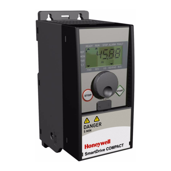
Page 28: Control Panel
Control Panel Honeywell 7. CONTROL PANEL 7.1 GENERAL The panel is integrated to the drive consisting of corresponding application card and an overlay on the drive cover with status display and button clarifications. The Control panel consists of an LCD display with backlight and a keypad including a navigation wheel, a green START button and a red STOP button (see Figure 7.1). -
Page 29: Keypad
Control Panel Honeywell Figure 7.1: SmartDrive Compact Control panel 7.3 KEYPAD The keypad section of the control panel consists of a navigation wheel and START and STOP buttons (see Figure 7.1). The navigation wheel is used for navigating on the panel display, but it also works as a reference potentiometer when KEYPAD has been selected as the control place of the drive. -
Page 30: Navigation On The Smartdrive Compact Control Panel
This chapter provides you with information on navigating the menus on SmartDrive Compact and editing the values of the parameters. 7.4.1 Main menu The menu structure of SmartDrive Compact control software consists of a main menu and several submenus. Navigation in the main menu is shown below: READY RUN... -
Page 31: Reference Menu
Control Panel Honeywell 7.4.2 Reference menu READY RUN STOP ALARM FAULT I/O KEYPAD Push to enter Change Push to edit mode value confirm Figure 7.3: Reference menu display Move to the reference menu with the navigation wheel (see Figure 7.2). The refe- rence value can be changed with the navigation wheel as shown in Figure 7.3. - Page 32 PI setpoint reference In percent of the maximum actual M1.18 PI feedback value In percent of the maximum error M1.19 PI error value value In percent of the maximum output M1.20 PI Output value Table 7.1 : SmartDrive Compact monitoring signals...
-
Page 33: Parameter Menu
Control Panel Honeywell 7.4.4 Parameter menu In Parameter menu only the Quick setup parameter list is shown by default. By giving the right value to the parameter 13.1 it is possible to open other advanced parameter groups. The parameter lists and descriptions can be found in chapters 8 and 9. -
Page 34: Fault History Menu
Control Panel Honeywell 7.4.5 Fault history menu READY RUN STOP ALARM FAULT READY RUN STOP ALARM FAULT Push I/O KEYPAD I/O KEYPAD Browse faults 1-9 READY RUN STOP ALARM FAULT READY RUN STOP ALARM FAULT Push I/O KEYPAD KEYPAD Browse... -
Page 35: Parameters
Parameters Honeywell 8. PARAMETERS On the next pages you can find the lists of parameters within the respective param- eter groups. The parameter descriptions are given in Chapter 9. NOTE: Parameters can only be changed when drive is in stop mode! -
Page 36: Quick Setup Parameters (Virtual Menu, Shows When Par. 3.1 = 1)
Parameters Honeywell 8.1 QUICK SETUP PARAMETERS (VIRTUAL MENU, SHOWS WHEN PAR. 3.1 = 1) Code Parameter Unit Default Note Motor nominal Check rating plate on the P1.1 voltage motor Motor nom. fre- Check rating plate on the P1.2 50,00 quency... - Page 37 Parameters Honeywell Code Parameter Unit Default Note 2 = Current 0…20 mA P6.5 AI2 Signal range 3 = Current 4…20 mA P10.4 Automatic restart 731 0 = Not used 1 = Used 0 = All parameters visible Parameter P13.1 1 = Only quick setup...
-
Page 38: Motor Settings (Control Panel: Menu Par -> P1)
Parameters Honeywell 8.2 MOTOR SETTINGS (CONTROL PANEL: MENU PAR -> P1) Code Parameter Unit Default Note Motor nominal Check rating plate on the P1.1 voltage motor Motor nominal Check rating plate on the P1.2 50,00 frequency motor Motor nominal Default applies for a 4-pole P1.3... -
Page 39: Start/Stop Setup (Control Panel: Menu Par -> P2)
Parameters Honeywell 8.3 START/STOP SETUP (CONTROL PANEL: MENU PAR -> P2) Code Parameter Unit Default Note 1 = I/O terminal P2.1 Control place 2 = Keypad 3 = Fieldbus 0 = Ramp P2.2 Start function 1 = Flying start 0 = Coasting P2.3... -
Page 40: Ramps And Brakes Setup (Control Panel: Menu Par -> P4)
Parameters Honeywell 8.5 RAMPS AND BRAKES SETUP (CONTROL PANEL: MENU PAR -> P4) Code Parameter Unit Default Note 0 = Linear P4.1 Ramp shape 10,0 >0 = S-curve ramp time P4.2 Acceleration time 3000 P4.3 Deceleration time 3000 DC braking... -
Page 41: Analogue Inputs (Control Panel: Menu Par -> P6)
Parameters Honeywell Code Parameter Unit Default Note P5.8 Preset speed B0 419 As parameter 5.1 P5.9 Preset speed B1 420 As parameter 5.1 P5.10 Preset speed B2 421 As parameter 5.1 P5.11 Disable PI 1020 As parameter 5.1 P5.12 Force to I/O 409 As parameter 5.1... -
Page 42: Digital And Analogue Outputs (Control Panel: Menu Par -> P7)
Parameters Honeywell 8.8 DIGITAL AND ANALOGUE OUTPUTS (CONTROL PANEL: MENU PAR -> P7) Code Parameter Min Max Unit Default Selections 0 = Not used 1 = Ready 2 = Run 3 = Fault 4 = Fault Inverted Relay output 1 5 = Warning P7.1... -
Page 43: Protections (Control Panel: Menu Par -> P9)
Parameters Honeywell 8.9 PROTECTIONS (CONTROL PANEL: MENU PAR -> P9) Code Parameter Unit Default Note Response to 4mA P9.1 reference fault Response to under P9.2 voltage fault 0 = No response P9.3 Earth fault protection 1 = Warning P9.4 Stall protection 2 = Fault, stop acc. -
Page 44: Pi Control Parameters (Control Panel: Menu Par -> P12)
Parameters Honeywell 8.11 PI CONTROL PARAMETERS (CONTROL PANEL: MENU PAR -> P12) Code Parameter Unit Default Note 0 = Not used P12.1 PI activation 1 = PI for motor control 2 = PI for external use P12.2 PI controller gain... -
Page 45: Easy Usage Menu (Control Panel: Menu Par -> P0)
Parameters Honeywell 8.12 EASY USAGE MENU (CONTROL PANEL: MENU PAR -> P0) Code Parameter Unit Default Note 0 = All parameters visible Parameter P13.1 1 = Only quick setup parameter conceal group visible 0 = Basic 1 = Pump drive 2 = Fan drive P13.2 Drive setup... - Page 46 Parameters Honeywell Code Parameter Default Note 0 = Not used, Communication time- S2.7 1 = 1 second, 2 = 2 seconds, etc. Reset communica- S2.8 1 = Resets par. S2.1 tion status Total counters (MENU PAR -> S3) S3.1 MWh counter S3.2 Power on days...
-
Page 47: Parameter Descriptions
Parameter Descriptions Honeywell 9. PARAMETER DESCRIPTIONS On the next pages you can find the descriptions of certain parameters. The descrip- tions have been arranged according to parameter group and number. 9.1 MOTOR SETTINGS (CONTROL PANEL: MENU PAR -> P1) OTOR CONTROL MODE With this parameter the user can select the motor control mode. - Page 48 Parameter Descriptions Honeywell U[V] Default: Nominal par.1.11 Field weakening voltage of the motor point Linear Squared Default: Nominal frequency of the motor f[Hz] par. 1.14 par.1.10 Figure 9.1: Linear and squared change of motor voltage 2 = Programmable U/f curve: The U/f curve can be programmed with three different points.
- Page 49 1.16 WITCHING FREQUENCY Motor noise can be minimised using a high switching frequency. Increasing the switching frequency reduces the capacity of the inverter unit. Switching frequency for SmartDrive Compact: 1.5…16 kHz.
- Page 50 Parameter Descriptions Honeywell 1.17 RAKE CHOPPER Note: An internal brake chopper is installed in three phase supply MI2 and MI3 size drives 0 = No brake chopper used 1 = Brake chopper used in Run state 2 = Used in Run and Stop state...
-
Page 51: Start/Stop Setup (Control Panel: Menu Par -> P2)
Local = Keypad is the control place Remote = P2.1 defines the control place TART FUNCTION The user can select two start functions for SmartDrive Compact with this pa- rameter: 0 = Ramp start The inverter starts from 0 Hz and accelerates to the set frequency ref- erence within the set acceleration time (P4.2). - Page 52 Parameter Descriptions Honeywell 1 = Ramp stop After the Stop command, the speed of the motor is decelerated accord- ing to the set deceleration parameters. If the regenerated energy is high it may be necessary to use an exter- nal braking resistor for to be able to decelerate the motor in acceptable time.
- Page 53 Parameter Descriptions Honeywell 1 = DI1 = Start DI2 = Reverse Figure 9.4: Start/Stop logic, selection 1 2 = DI1 = Start pulse DI2 = Stop pulse Figure 9.5: Start/Stop logic, selection 2 3 = DI1 = Start forward, rising edge after fault...
-
Page 54: Frequency References (Control Panel: Menu Par -> P3)
Parameter Descriptions Honeywell OCAL EMOTE This parameter defines whether the control place of the drive is remote (I/O or FieldBus) or Keypad. Keypad can also be selected as control place by press- ing the navigation wheel for 5 seconds. The priority order of selecting control place is 1. -
Page 55: Ramps & Brakes Setup (Control Panel: Menu Par -> P4)
Parameter Descriptions Honeywell 9.4 RAMPS & BRAKES SETUP (CONTROL PANEL: MENU PAR -> P4) AMP SHAPE 4.10 AMP SHAPE The start and end of the acceleration and deceleration ramp can be smoothed with this parameter. Setting value 0 gives a linear ramp shape which causes acceleration and deceleration to act immediately to the changes in the refer- ence signal. - Page 56 Parameter Descriptions Honeywell C BRAKING TIME AT START DC-brake is activated when the start command is given. This parameter de- fines the time before the brake is released. After the brake is released, the out- put frequency increases according to the set start function by par. 2.2.
- Page 57 Parameter Descriptions Honeywell BRAKING TIME AT STOP Determines if braking is ON or OFF and the braking time of the DC-brake when the motor is stopping. The function of the DC-brake depends on the stop function, par. 2.3. 0 = DC brake is not in use >0 = DC brake is in use and its function depends on the Stop function,...
- Page 58 Parameter Descriptions Honeywell The braking time is defined with parameter 4.7. If high inertia exists, it is rec- ommended to use an external braking resistor for faster deceleration. See Fig- ure 9.9. f out Motor speed Output frequency DC-braking Par. 4.6 t = par.
-
Page 59: Digital Inputs (Control Panel: Menu Par -> P5)
Parameter Descriptions Honeywell 9.5 DIGITAL INPUTS (CONTROL PANEL: MENU PAR -> P5) The selections for these parameters are: 0 = Not used 1 = DI1 2 = DI2 3 = DI3 4 = DI4 5 = DI5 6 = DI6... -
Page 60: Analoque Inputs (Control Panel: Menu Par -> P6)
Parameter Descriptions Honeywell 9.6 ANALOQUE INPUTS (CONTROL PANEL: MENU PAR -> P6) SIGNAL FILTER TIME SIGNAL FILTER TIME This parameter, given a value greater than 0, activates the function that filters out disturbances from the incoming analogue signal. Long filtering time makes the regulation response slower. -
Page 61: Motor Thermal Protection (Parameters 9.7 - 9.10)
Parameter Descriptions Honeywell 9.8 MOTOR THERMAL PROTECTION (PARAMETERS 9.7 - 9.10) The motor thermal protection is to protect the motor from overheating. The Honey- well drive is capable of supplying higher than nominal current to the motor. If the load requires this high current there is a risk that the motor will be thermally overloaded. - Page 62 Parameter Descriptions Honeywell OTOR COOLING FACTOR AT ZERO SPEED The cooling power can be set between 0-150.0% x cooling power at nominal frequency. See Figure 9.11. P cooling Overload area 100% par.9.9=40% Figure 9.11: Motor cooling power 9.10 OTOR THERMAL TIME CONSTANT This time can be set between 1 and 200 minutes.
- Page 63 Parameter Descriptions Honeywell If the motor's t6-time (t6 is the time in seconds the motor can safely operate at six times the rated current) is known (given by the motor manufacturer) the time constant parameter can be set basing on it. As a rule of thumb, the motor thermal time constant in minutes equals to 2xt6.
-
Page 64: Autorestart Parameters (Control Panel: Menu Par -> P10)
Parameter Descriptions Honeywell 9.9 AUTORESTART PARAMETERS (CONTROL PANEL: MENU PAR -> P10) 10.2 UTOMATIC RESTART TRIAL TIME The Automatic restart function restarts the inverter when the faults have dis- appeared and the waiting time has elapsed. The time count starts from the first autorestart. If the number of faults occurring during the trial time exceeds three, the fault state becomes active. - Page 65 Parameter Descriptions Honeywell 12.7 EEDBACK MINIMUM 12.8 EEDBACK MAXIMUM Controller feedback (%) par. 12.8 par. 12.7 Analoque input with custom min and max Custom min Custom max scaling (%) par. 6.3/6.7 par.6.4/6.8 20mA Figure 9.14: Feedback minimum and maximum...
-
Page 66: Easy Usage Menu (Control Panel: Menu Par -> P9)
Parameter Descriptions Honeywell 9.11 EASY USAGE MENU (CONTROL PANEL: MENU PAR -> P9) 13.2 D RIVE SETUP With this parameter you can easily set up your drive for four different applica- tions. Note! This parameter is only visible when the Startup Wizard is active. The startup wizard will start in first power-up. -
Page 67: Fieldbus Parameters (Control Panel: Menu Par -> S2)
Parameter Descriptions Honeywell Figure 9.16: Drive setup 9.12 FIELDBUS PARAMETERS (CONTROL PANEL: MENU PAR -> S2) The built-in Modbus connection of SmartDrive Compact supports the following func- tion codes: - 03 Read Holding Registers - 04 Read Input Registers - 06 Preset Single Registers... -
Page 68: Modbus Process Data
Parameter Descriptions Honeywell 9.12.1 Modbus process data Process data is an address area for fieldbus control. Fieldbus control is active when the value of parameter 2.1 (Control place) is 3 (=fieldbus). The contents of the proc- ess data has been determined in the application. The following tables present the process data contents in the GP Application. - Page 69 Table 9.7: Control word In Honeywell applications, the three first bits of the control word are used to control the inverter. However, you can customise the content of the control word for your own applications because the control word is sent to the inverter as such.
- Page 70 Parameter Descriptions Honeywell Description Value = 0 Value = 1 Stop Clockwise Counter-clockwise Rising edge of this bit will reset active fault Drive not ready Drive ready No fault Fault active No warning Warning active AREF Ramping Speed reference reached Drive is running at zero speed Table 9.9: Bit definitions...
-
Page 71: Technical Data
45…66 Hz connection Line current THD > 120% Connection to mains Once per minute or less (normal case) Supply SmartDrive Compact cannot be used with corner network grounded networks 0 - U Output voltage Continuous rated current I at ambient tempera- Output current ture max. - Page 72 For EMC: EN61800-3, Standards For safety: UL508C, EN61800-5 Certificates For safety: CB, CE, UL, cUL, manufacturer’s For EMC: CE, CB, c-tick declarations of (see unit nameplate for more detailed approvals) conformity Table 10.1 : SmartDrive Compact technical data...
-
Page 73: Power Ratings
COMP230-P75-20 0,75 MI2 0,70 COMP230-1P1-20 11,2 MI2 0,70 COMP230-1P5-20 10,5 14,1 MI2 0,70 COMP230-2P2-20* 14,4 15,8 MI3 0,99 Table 10.2 : SmartDrive Compact power ratings, 208 - 240 V, 1~ * The maximum ambient operating temperature of COMP230-2P2-20 is +40°C! -
Page 74: Smartdrive Compact - Mains Voltage 380 - 480 V
12,0 18,0 14,9 MI3 0,99 Table 10.3 : SmartDrive Compact power ratings, 380 - 480 V * The maximum ambient operating temperature of COMP400-5P5-20 is +40°C! Note 1: The input currents are calculated values with 100 kVA line transformer supply. - Page 75 Find out more For more information on Honeywell’s frequency converters and other Honeywell products, visit us online at http://inverter.ecc.emea.honeywell.com Automation and Control Solutions Honeywell GmbH Böblinger Str. 17 71101 Schönaich, Germany Telephone (49) 7031 637 01 EN1B-0430GE51 R0711 Telefax (49) 7073 637 493 July 2011 http://inverter.ecc.emea.honeywell.com...