
Subscribe to Our Youtube Channel
Related Manuals for GE MDS 4710A


Summary of Contents for GE MDS 4710A
- Page 1 MDS 4710/9710 Series (Including: MDS 4710A/C/M and MDS 9710A/C/M/T) 400 MHz and 900 MHz Remote Data Transceivers MDS 05-3305A01, Rev. E OCTOBER 2011...
- Page 2 QUICK START GUIDE Below are the basic steps for installing the transceiver. See “INSTALLATION” on Page 5 of this guide for detailed instructions. Install and connect the antenna system to the radio • Use good quality, low loss coaxial cable. Keep the feedline as short as possible. •...
-
Page 3: Table Of Contents
TABLE OF CONTENTS 1.0 GENERAL ................... 1 1.1 Introduction ..................1 1.2 Applications ..................2 Point-to-Multipoint, Multiple Address Systems (MAS) ...... 2 Point-to-Point System ............... 3 Continuously-Keyed versus Switched-Carrier Operation....3 Single-Frequency (Simplex) Operation..........4 1.3 Model Number Codes ..............4 1.4 Contents of Standard Shipping Packages ........ - Page 4 Major Alarms vs. Minor Alarms ............33 Event Code Definitions ..............34 6.0 TECHNICAL REFERENCE ............35 6.1 MDS 4710A/C/M and 9710A/C/M/T Transceiver Specifications ..35 6.2 Helical Filter Adjustment ..............36 6.3 Performing Network-Wide Remote Diagnostics ......37 6.4 User-Programmable Interface Output Functions ......39 6.5 Upgrading the Radio’s Software ............40...
-
Page 5: Copyright Notice
Copyright Notice This Installation and Operation Guide and all software described herein are protected by copyright: 2010 GE MDS, LLC. All rights reserved. GE MDS, LLC reserves its right to correct any errors and omissions in this publication. Revision Notice... - Page 6 Antenna Installation Warning 1. All antenna installation and servicing is to be performed by qualified technical personnel only. When servicing the antenna, or working at distances closer than those listed below, ensure the transmitter has been disabled. Output is measured at the antenna terminal of the transmitter. The antenna(s) used for this transmitter must be fixed-mounted on outdoor permanent structures to provide the minimum separation distances described in this filing for satisfying RF exposure...
- Page 7 • A power connector with screw-type retaining screws as supplied by GE MDS must be used. Do not disconnect equipment unless power has been switched off or the area is known to be non-hazardous.
- Page 8 Distress Beacon Warning In the U.S.A., the 406 to 406.1 MHz band is reserved for use by distress beacons. Since the radio described in this manual is capable of transmit- ting in this band, take precautions to prevent the radio from transmitting between 406 to 406.1 MHz in U.S.
-
Page 9: General
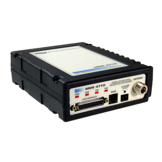
1.0 GENERAL 1.1 Introduction This guide presents installation and operating instructions for the MDS 4710A/9710A and the MDS 4710C/9710C Series (400/900 MHz) digital radio transceivers. These transceivers (Figure 1) are data telemetry radios designed to operate in a point-to-multipoint environment, such as electric utility... -
Page 10: Applications
1.2 Applications Point-to-Multipoint, Multiple Address Systems (MAS) This is the most common application of the transceiver. It consists of a central master station and several associated remote units as shown in Figure 2. A MAS network provides communication between a central host computer and remote terminal units (RTUs) or other data collection devices. -
Page 11: Point-To-Point System
Point-to-Point System Where permitted, the transceiver can also be used in a point-to-point system. A point-to-point system consists of two radios, one serving as a master and the other as a remote (Figure 3). This system provides a sim- plex or half-duplex communication link for the transfer of data between two locations. -
Page 12: Single-Frequency (Simplex) Operation
This number is subject to many variations depending on what options are installed, and in which country the product is used. Contact GE MDS if you have questions on the meaning of the code. 1.4 Contents of Standard Shipping Packages... -
Page 13: Accessories
1.5 Accessories The transceiver can be used with one or more of the accessories listed in Table 3. Contact GE MDS for ordering information. Table 3. Optional Accessories for MDS 4710/9710 Transceivers GE MDS Accessory Description Power Supply Kit Provides nominal 13.8 Vdc from a 01-3682A01 120 Vac power source. -
Page 14: Installation Steps
Invisible place holder REMOTE TERMINAL UNIT ANTENNA SYSTEM RADIO TRANSCEIVER 13.8 VDC POWER CABLE LOW-LOSS FEEDLINE 13.8 VDC 2.5 A (MINIMUM) POWER SUPPLY Figure 4. Typical Remote Station Arrangement 2.1 Installation Steps Below are the basic steps for installing the transceiver. In most cases, these steps alone are sufficient to complete the installation. -
Page 15: Transceiver Mounting
4. Measure and install the primary power for the radio. The red wire on the GE MDS-provided power cable is the positive lead; the black is negative. Only use the MDS 4710/9710 radio transceivers in nega- CAUTION tive-ground systems. POSSIBLE... - Page 16 Invisible place holder 8.5 in. 216 mm 6.63 in. 168 mm ALTERNATE POSITION 5.625 in. 143 mm Figure 5. Transceiver Mounting Dimensions CAUTION Using screws longer than 1/4 inch (6 mm) to attach the brackets to the radio might damage the internal PC board. Use only the POSSIBLE supplied screws.
-
Page 17: Antennas And Feedlines
2.3 Antennas and Feedlines Antennas The transceiver can be used with a number of antenna styles. The exact style depends on the physical size and layout of the radio system. A directional Yagi (Figure 6) or corner reflector antenna is generally rec- ommended at remote sites to minimize interference to and from other users. -
Page 18: Power Connection
Normally, the transceiver is ade- quately grounded if the GE MDS mounting brackets are used to secure the radio to a well-grounded metal surface. If the transceiver is not mounted to a grounded surface, connect a safety ground to the transceiver case. -
Page 19: Data Interface Connections
2.6 Data Interface Connections DATA INTERFACE Connect the transceiver’s connector to an external DTE data terminal that supports the EIA-232 (formally RS-232) format. The transceiver supports autobaud asynchronous data rates of up to DATA INTERFACE 19200 bps. The data rate at the connector might differ from the data rate used over the air. -
Page 20: Using The Radio's Sleep Mode
Do not connect—Reserved for future use. PTT—Push-to-Talk. This line is used to key the radio with an active-high signal of +5 Vdc. User-Programmable Output 2—EIA-232-compatible output controllable though GE MDS’ InSite NMS program. See “User-Programmable Interface Output Functions” on Page 39 for details. -
Page 21: System Example
NOTE: GE MDS recommends against applying RS-232 voltages to Pin 12 of the radio’s DB 25 connector. Only apply ground or +5 Vdc to this pin. GE MDS recommends that you connect the radio and RTU using the circuit shown in... -
Page 22: Led Indicators
If all parameters are correctly set, start radio operation by following these steps: 1. Apply DC power to the transceiver. 2. Observe the LED status panel for the proper indications (Table 3. If not done earlier, refine the antenna heading of the station to maxi- mize the received signal strength (RSSI) from the master station. -
Page 23: Transceiver Programming
Contact GE MDS for ordering information. 4.1 Hand-Held Terminal Connection & Startup This section provides basic information for connecting and using the GE MDS Hand-Held Terminal. For more information about the terminal, refer to the instructions included with the HHT kit. -
Page 24: Hand-Held Terminal Setup
2. When the HHT is connected, it runs through a brief self-check, and ends with a beep. After the beep, press to receive the ready ENTER “>” prompt. Invisible place holder Figure 9. Hand-Held Terminal Connected to the Transceiver 4.2 Hand-Held Terminal Setup Perform the following steps to re-initialize an HHT for use with the transceiver. -
Page 25: Keyboard Commands
2. The display shows the first of 15 menu items. To review settings, press the key. This controls the NEXT function. To change parameter settings, press the key. This controls the ROLL func- tion. 3. Configure the HHT as listed in Table Table 8. - Page 26 Additional points to remember when using the HHT: • Use the key to access numbers; press again to return to letter SHIFT mode. • Use the key to edit information or command entries. ESC/BKSP • The flashing square cursor ( ) indicates that Letter Mode is selected.
-
Page 27: Error Messages
ACCESS DENIED—The command is unavailable to the user. Refer to the com- mand descriptions for command information. EEPROM FAILURE— The INIT command was unable to write to EEPROM. This is a serious internal radio error. Contact GE MDS. Table 9 for a summary of the user commands. - Page 28 Table 9. Command Summary (Continued) Command name Function (Diagnostics) Sets up a radio as a root or node DTYPE [NODE/ROOT] radio. Details Page 26 Display all programmable settings. DUMP Details Page 26 Display the Hardware Revision level. HREV Details Page 27 Set radio parameters to factory defaults.
-
Page 29: Detailed Command Descriptions
Table 9. Command Summary (Continued) Command name Function Set or display the transmit frequency. TX [xxx.xxxx] Details Page Set or display the transmit audio input level. TXLEVEL [–20 to +6, AUTO] Details Page 32 Set or display the transceiver’s unit address. UNIT [10000...65000] Details Page 32 4.4 Detailed Command Descriptions... - Page 30 The eight-digit hexadecimal number used as the command parameter specifies 0 to 32 events that can trigger the external alarm output (see Table below for a list of events). The hex value for the mask corre- sponds to the hex value for the command (Page 31).
-
Page 31: Asense [Hi/Lo]
Table 10. Alarm Event Codes and Hex/Binary Values Alarm Code Event Number Text Message 32-bit Binary Equivalent (hex) Total current fault 0000 0008 0000 0000 0000 0000 0000 0000 0000 1000 Power output control 0000 0004 0000 0000 0000 0000 0000 0000 0000 0100 RSSI reading below -105 0000 0002 0000 0000 0000 0000 0000 0000 0000 0010... -
Page 32: Baud [Xxxxx Abc]
BAUD [xxxxx abc] Data Interface Port This command sets (or displays) the communication attributes for the Baud Rate DATA INTERFACE DIAG port. It has no effect on the RJ-11 port. The first parameter ( ) is baud rate. Baud rate is specified in xxxxx bits-per-second (bps) and must be set to one of the following speeds: 1200, 2400, 4800, 9600, or 19200. -
Page 33: Ckey [On-Off]
CKEY [ON–OFF] Key TX command enables or disables the continuously-keyed func- CKEY Continuously tion of the radio. When is set to , the radio is continuously keyed CKEY and the Timeout Timer is disabled. CTS [0–255] (clear-to-send) command selects or displays the timer value Clear-to-Send Time associated with the CTS line response. -
Page 34: Dkey
DKEY Unkey Transmitter This command deactivates the transmitter after it has been keyed with command. DIN [ON/OFF] When is selected, the “not” PTT line (Pin 16 on the DB-25 con- Digital Input DIN ON nector) is re-defined as a digital input for network-wide diagnostics. See “User-Programmable Interface Output Functions”... -
Page 35: Hrev
HREV Hardware Revision This command displays the transceiver’s hardware revision level. If nothing is displayed, the hardware revision level was not programmed by the factory. INIT command is used to re-initialize the radio’s operating parame- Initialize EEPROM INIT Defaults ters to the factory defaults. This is helpful when trying to resolve con- figuration problems that might have resulted from the entry of one or more improper command settings. -
Page 36: Key
TX Key This command activates the transmitter. See also the command. DKEY MODEL This command displays the radio’s model number code. Model Number Code MODEM [xxxx, NONE] This command selects the radio’s modem characteristics. For digital Analog/Digital Modem Selection operation, enter (MDS x710A) or (MDS x710C). -
Page 37: Rssi
This command enables or disables the radio’s internal RTU simulator, RTU Simulator which runs with GE MDS’ proprietary polling programs (poll.exe and rsim.exe). The internal RTU simulator is available whenever diagnos- tics is enabled in a radio. This command also sets the RTU address to which the radio will respond. -
Page 38: Rxlevel [-20 To +6]
RXLEVEL [–20 to +6] RX Audio Output selects or displays the receive output level RXLEVEL command Level DATA INTERFACE present on Pin 11 of the ’s DB-25 connector. Use this function in mode with analog audio. MODEM NONE RXTOT [NONE, 1-1440] Loss of RX Data command selects or displays the receive time-out timer value RXTOT... -
Page 39: Srev
DIAG Using the SNR command causes the port to enter an update mode, and the SNR is updated and redisplayed every 2 sec. The SNR continu- ously updates until you press the key. ENTER SREV Software/Firmware This command displays the software revision level of the transceiver Revision Level firmware. -
Page 40: Txlevel [-20 To +6, Auto]
TXLEVEL [–20 to +6, AUTO] TX Audio Input Level selects or displays the transmit audio input level TXLEVEL command DATA INTERFACE expected on Pin 9 of the ’s DB-25 connector from an DATA INTERFACE external modem present on Pin 11 of the ’s DB-25 connector. -
Page 41: Event Codes
(or seriously hampers) further operation of the transceiver. Major alarms generally indicate the need for factory repair. Contact GE MDS for further assis- tance. Minor Alarms—report conditions that, under most circumstances, do not prevent transceiver operation. -
Page 42: Event Code Definitions
Event Code Definitions Table 11 contains a listing of all event codes reported by the transceiver. Table 11. Event Codes Event Event Code Class Description Major Improper software detected for this radio model. Major The model number of the transceiver is unprogrammed. Major One or both of the internal programmable synthesizer loops is reporting an out-of-lock condition. -
Page 43: Technical Reference
6.0 TECHNICAL REFERENCE 6.1 MDS 4710A/C/M and 9710A/C/M/T Transceiver Specifications GENERAL Frequency Range*: MDS 4710A/C/M MDS 9710A/C/M/T 330–512 MHz 800–960 MHz * with one or more sub-bands as permitted by regulatory agencies Frequency Stability: ±1.5 ppm RECEIVER –6 Maximum Usable Sensitivity: MDS x710A/T: –110 dBm at 1x10... -
Page 44: Helical Filter Adjustment
See “Performing Network-Wide Remote Diagnostics” on Page I/O Devices: GE MDS Hand-Held Terminal, PC with GE MDS software, or other Terminal Communications program. 6.2 Helical Filter Adjustment If the frequency of the radio is changed more than 5 MHz, adjust the helical filters for maximum received signal strength (RSSI) as follows: 1. -
Page 45: Performing Network-Wide Remote Diagnostics
Figure 12. Helical Filter Locations 6.3 Performing Network-Wide Remote Diagnostics Diagnostics data from a remote radio can be obtained by connecting a laptop or personal computer running GE MDS InSite NMS software to any radio in the network. Figure 13 shows an example of a setup for per- forming network-wide remote diagnostics. - Page 46 DTYPE ROOT A complete explanation of remote diagnostics can be found in GE MDS’ Network-Wide Diagnostics System Handbook. See the handbook for more information about the basic diagnostic procedures outlined below.
-
Page 47: User-Programmable Interface Output Functions
(TO COMPUTER) (TO RADIO) RJ-11 PIN LAYOUT Figure 14. RJ-11 to DB-9 Adapter Cable 7. Start the GE MDS InSite application at the PC (see the GE MDS InSite User’s Guide for instructions). 6.4 User-Programmable Interface Output Functions You can manually activate two pins of the DATA INTERFACE using GE MDS’... -
Page 48: Upgrading The Radio's Software
6.5 Upgrading the Radio’s Software Windows-based Radio Configuration software is available (MDS P/N 03-3156A01) for upgrading the internal radio software when new fea- tures become available from GE MDS. Contact GE MDS for ordering information, or download new radio software from www.gemds.com. DIAG To connect a PC to the radio’s... -
Page 49: External Orderwire Module
Master Station and the Remote Station sites to coordinate their activities. An optional external orderwire module from GE MDS (P/N 12-1297A01) is available that can be inserted between the radio’s DATA INTERFACE and the user’s data communication device. - Page 50 12-1307A01 without PTT; 12-1307A01 with PTT) can be purchased from GE MDS. Handsets must have carbon microphone elements installed. Dynamic microphones do not work with the module. Handsets with a push-to-talk (PTT) button are supported and recommended, as background noise can activate the VOX circuit and interrupt the payload data.
- Page 51 6.7 dBm-Watts-Volts Conversion Chart Table 13 is provided as a convenience for determining the equivalent wattage or voltage of an RF power expressed in dBm. Table 13. dBm-Watts-Volts Conversion—for 50 Ohm Systems dBm V dBm V dBm mV dBm µV 100.0 200W .225 1.0mW...
-
Page 52: Glossary Of Terms
7.0 GLOSSARY OF TERMS If you are new to digital radio systems, some of the terms used in this guide may be unfamiliar. The following glossary explains many of these terms and will prove helpful in understanding the operation of the trans- ceiver. - Page 53 DSP—Digital Signal Processing. In the MDS 4710/9710 transceiver, the DSP circuitry is responsible for the most critical real-time tasks; pri- marily modulation, demodulation, and servicing of the data port. DTE—Data Terminal Equipment. A device that provides data in the form of digital signals at its output. Connects to the DCE device. Equalization—The process of reducing the effects of amplitude, fre- quency or phase distortion with compensating networks.
- Page 54 Network-Wide Diagnostics—An advanced method of controlling and interrogating GE MDS radios in a radio network. Non-intrusive diagnostics—See Passive messaging. Passive messaging—This is a mode of diagnostic gathering that does not interrupt SCADA system polling communications. Diagnostic data is collected non-intrusively over a period of time; polling messages are carried with SCADA system data (contrast with active messaging).
- Page 55 NOTES MDS 05-3305A01, Rev. E MDS 4710/9710 Technical Manual...
- Page 56 MDS 4710/9710 Technical Manual MDS 05-3305A01, Rev. E...
-
Page 57: Technical Assistance
IN CASE OF DIFFICULTY... GE MDS products are designed for long life and trouble-free operation. However, this equipment, as with all electronic equipment, may have an occasional component failure. The following information will assist you in the event that servicing becomes necessary. - Page 58 GE MDS, LLC 175 Science Parkway Rochester, NY 14620 General Business: +1 585 242-9600 FAX: +1 585 242-9620 www.gemds.com...
- Page 59 INDEX DTYPE (set radio to root or node for diagnostics) 26 DUMP (display all programmed settings) 26 ACCESS DENIED error message 19 entering on Hand-Held Terminal (HHT) 17 Accessories 5 Hand-Held Terminal (HHT) 17 Accessory Power pinout (Pin 18) 12 HREV (display hardware revision level) 27 Active messaging (defined) 44 INIT (reinitialize radio to factory defaults) 27...
- Page 60 Digital Signal Processing—See DSP. 44 Feedlines 9 Display Filter, helical, adjustment 36 alarm status (STAT command) 31 Frame, defined 45 alarm triggers (AMASK command) 21 Frequency all programmed settings (DUMP command) 26 adjusting helical filter when changed 36 baud rate and encoding (BAUD command) 24 setting.
- Page 61 Interface Output Functions 39 Orderwire Module 41 Intrusive diagnostics (defined) 45 Output, 9.9 Vdc regulated, pinout (Pin 19) 12 OWM command 28 OWN command 28 Owner’s message, set/display. See OWM command KEY command 28 Owner’s name, set/display. See OWN command Keyboard Commands Command Summary 19 Entering Commands 17...
- Page 62 unsquelched signal (Pin 10) 11 receiver 36 Redundant operation, defined 46 receiver system 35 Remote transceiver 35–36 Station, defined 46 transmitter 35 Station, illustrated 6 transmitter system 35 Resetting SREV command 31 Hand-Held Terminal (HHT) (SHIFT,CTRL,SPACE Standing Wave Ratio—See SWR. 46 keys) 16 STAT command 31 transceiver (INIT command) 27...
- Page 63 IN CASE OF DIFFICULTY... GE MDS products are designed for long life and trouble-free operation. However, this equipment, as with all electronic equipment, may have an occasional component failure. The following information will assist you in the event that servicing becomes necessary.
- Page 64 GE MDS, LLC 175 Science Parkway Rochester, NY 14620 General Business: +1 585 242-9600 FAX: +1 585 242-9620 www.gemds.com...
Need help?
Do you have a question about the MDS 4710A and is the answer not in the manual?
Questions and answers