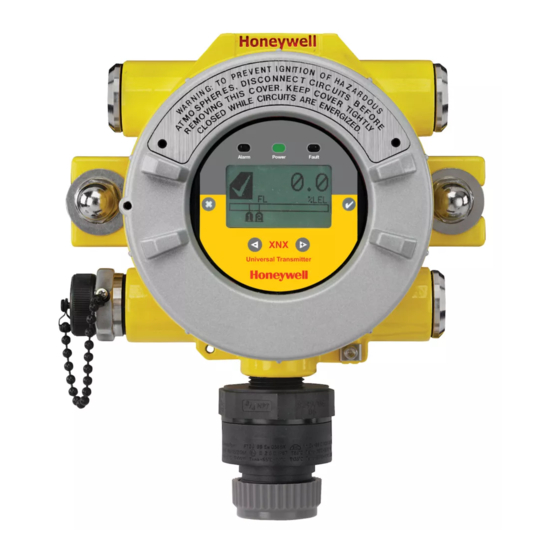
Honeywell XNX Safety Manual
Universal transmitter
Hide thumbs
Also See for XNX:
- Technical manual (200 pages) ,
- Quick start manual (100 pages) ,
- Safety manual (15 pages)

Related Manuals for Honeywell XNX


Summary of Contents for Honeywell XNX
- Page 1 Universal Transmitter Safety Manual • Table of Contents • Fault Diagnostic Time Interval • SIL 2 Certificates • Proof Test • Overview • Proof Testing Procedure • Safety Parameters Revision 2...
-
Page 2: Table Of Contents
XNX Universal Transmitter Table of Contents 1 SIL 2 Certificates ............3 1.1 XNX Gas Detector Transmitter ......3 2 Overview .................4 3 Safety Parameters ............5 3.1 Interval of Proof Testing ........5 4 Fault Diagnostic Time Interval ........6 5 Proof Test ...............6 5.1 Purpose of Proof Testing ........6... -
Page 3: Sil 2 Certificates
XNX Universal Transmitter 1 SIL 2 Certificates 1.1 XNX Gas Detector Transmitter SIL 2 Certificates XNX Gas Detector Transmitter... -
Page 4: Overview
A Safety Integrity Level-certified system can detect the majority of XNX Transmitter Sensor safe and unsafe failures. XNX is SIL 2 capable per IEC 61508. XNX is SIL 3 capable in a redundant system per IEC 61508. Table 1 IR Personality... -
Page 5: Safety Parameters
3 Safety Parameters 3.1 Interval of Proof Testing If the XNX is used in high demand systems, a proof test is not required. The safety parameters listed below are a combination of the main If the XNX is used in low demand systems (defined as 1 demand or board and personality board. -
Page 6: Fault Diagnostic Time Interval
24 hours. But when a fault is if necessary, the system can be restored to an “as new” condition or detected, it is reported within 3 seconds. Refer to the XNX Technical as close as practical to this condition. -
Page 7: Proof Testing Procedure
Test Menu. For more information on setting If the mA output is not at the expected level when applying the mA output levels for normal operation, see mA Levels in the XNX calibration gas, refer to 6.2.2... -
Page 8: Zero Gas Calibration And Span Calibration
When the concentration values are stable select 6.2.2 Zero Gas Calibration and Span Calibration to allow the XNX to calculate the zero adjustment. Selecting ✓ The following section outlines the steps for calibrating the attached will return to the Gas Calibration Menu. -
Page 9: Span Calibration
XNX Universal Transmitter 6.2.2.2 Span Calibration Selecting will cancel the span calibration and return to the ✖ Gas Calibration Menu. NOTE: 4. When the sensor has completed the calibration and the span If a Span Calibration is not required, select to skip the Span ✖... -
Page 10: Verifying Ma Settings
#4 to adjust the values. WARNING NOTE While XNX is in Inhibit Mode, alarms are silenced. This will prevent If the values for the faults and warnings have been changed an actual gas event from being reported. Inhibit Mode must be reset from the default settings since installation, ensure the current after testing or maintenance activities. -
Page 11: Testing
Low Signal is from 1.0 to 4.0 mA and for an overrange condition, the range is 20.0 to 22.0 mA. Refer to Section 5 Warnings/Faults in the XNX Technical Manual for more information. 5. Once all changes have been made, use the switches to move to the ‘3’... -
Page 12: Gas Verification
XNX Universal Transmitter 4. To simulate a Warning or Fault from the XNX, select the As in an alarm simulation, a confirmation screen will appear. appropriate icon from the menu. Figure 21. Alarm/Fault Reset Screen Selecting will reset all alarms, faults or warnings generated Figure 18. - Page 14 Thank you for reading this data sheet. For pricing or for further information, please contact us at our UK Office, using the details below. UK Office Keison Products, P.O. Box 2124, Chelmsford, Essex, CM1 3UP, England. Tel: +44 (0)330 088 0560 Fax: +44 (0)1245 808399 Email: sales@keison.co.uk...