Cisco 8800 Manual
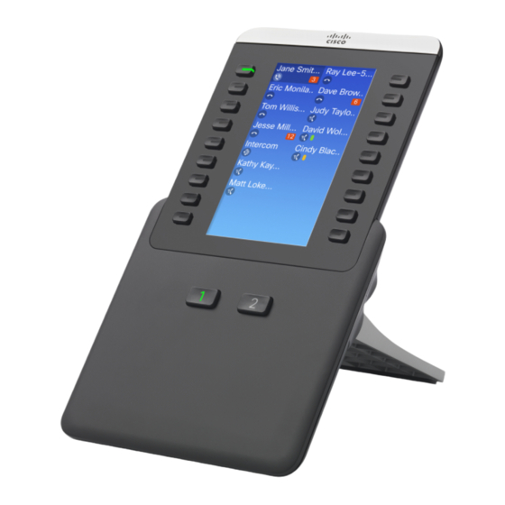
Expansion module
Hide thumbs
Also See for 8800:
- Manual (544 pages) ,
- Administration manual (406 pages) ,
- User manual (218 pages)
Advertisement
Quick Links
Cisco IP Phone Key Expansion Module
•
•
•
•
•
•
•
Cisco IP Phone Key Expansion Module Setup Overview
Key expansion modules add extra line appearances, speed dials, or programmable buttons to the phone. The
programmable buttons can be set up as phone line buttons, speed-dial buttons, or phone feature buttons
Caution
The slots in the side of the phone are designed only for use with the spine connectors on the key expansion
module. Insertion of other objects permanently damages the phone.
Cisco IP Phone 8800 Series Administration Guide for Cisco Unified Communications Manager
1
Advertisement

Related Manuals for Cisco 8800


Summary of Contents for Cisco 8800
-
Page 1: Table Of Contents
Key Expansion Module Power Information, page 2 • Connect a Key Expansion Module to a Cisco IP Phone, page 3 • Set up the Key Expansion Module in Cisco Unified Communications Manager, page 7 • Access Key Expansion Module Setup, page 9 •... -
Page 2: Key Expansion Module Power Information
You cannot add more features than the number of programmable line keys on your expansion module. Figure 1: Cisco IP Phone 8861 with Three Cisco IP Phone 8800 Key Expansion Modules Table 1: Cisco IP Phones and Supported Key Expansion Modules... -
Page 3: Connect A Key Expansion Module To A Cisco Ip Phone
Cisco IP Phone 8861 unless Cisco Universal PoE (UPoE) is used. • Cisco IP Phone 8851 with 2 expansion modules will work on 802.3at PoE only with v08 or later hardware. You can find the phone version information on the lower back of the phone as part of the TAN and PID label. - Page 4 Remove the two accessory connector covers, as shown in the diagram. The slots are designed for the spine connector only. Insertion of other objects will cause permanent Caution damage to the phone. Cisco IP Phone 8800 Series Administration Guide for Cisco Unified Communications Manager...
- Page 5 Position the phone so that the front of the phone faces up. Step 6 Connect one end of the key expansion module spine connector to the accessory connector on the Cisco IP Phone. a) Align the spine connector with the accessory connector ports.
- Page 6 This step ensures that the phone and key expansion module remain connected at all times. This diagram shows the location of the screw holes on the phone and one key expansion module. Cisco IP Phone 8800 Series Administration Guide for Cisco Unified Communications Manager...
-
Page 7: Set Up The Key Expansion Module In Cisco Unified Communications Manager
Before you install an expansion module on a phone, configure it in the Product Specific Configuration area of your Cisco Unified Communications Manager Administration. During the expansion module set up, you can configure the module to display on one-column or two-column mode. Cisco IP Phone 8800 Series Administration Guide for Cisco Unified Communications Manager... - Page 8 In two-column mode, each of the buttons on the left and right of the screen is assigned to different lines. In this configuration, the key expansion module displays 18 lines on page 1, and 18 lines on page 2. The following graphic shows the two-column mode. Cisco IP Phone 8800 Series Administration Guide for Cisco Unified Communications Manager...
-
Page 9: Access Key Expansion Module Setup
The Find and List Phones window appears with a list of phones that match your search criteria. Step 3 Click the phone that you want to configure for the Cisco IP Phone 8800 Key Expansion Module. The Phone Configuration window appears. -
Page 10: Reset The Single Lcd Screen Key Expansion Module
All properly installed and configured key expansion modules display in the list of accessories. Reset the Single LCD Screen Key Expansion Module If you are having technical difficulties with your Cisco IP Phone 8800 Key Expansion Module, you can reset the module to the factory default settings.