Grizzly G0453 Owner's Manual
15" & 20" mobile planers
Hide thumbs
Also See for G0453:
- Owner's manual (72 pages) ,
- Instruction manual (69 pages) ,
- Parts list (10 pages)
Table of Contents
Advertisement
Quick Links
For questions or help with this product contact Tech Support at (570) 546-9663 or techsupport@grizzly.com
The following change was recently made to these machines since the owner's manuals were
printed:
•
Outfeed roller changed from serrated steel to rubber.
Aside from this information, all other content in the owner's manual applies and MUST be read and under-
stood for your own safety. IMPORTANT: Keep this update with the owner's manual for future reference.
For questions or help, contact our Tech Support at (570) 546-9663 or techsupport@grizzly.com.
V2 Outfeed Roller
REF PART #
DESCRIPTION
81V2 P0453081V2
OUTFEED ROLLER (RUBBER) V2.09.17 (G0453)
63V2 P0453Z063V2 OUTFEED ROLLER (RUBBER) V2.09.17 (G0453Z)
89V2 P0454089V2
OUTFEED ROLLER (RUBBER) V2.09.17 (G0454)
68V2 P0454Z068V2 OUTFEED ROLLER (RUBBER) V2.09.17 (G0454Z)
WARNING: NO PORTION OF THIS MANUAL MAY BE REPRODUCED IN ANY SHAPE
OR FORM WITHOUT THE WRITTEN APPROVAL OF GRIZZLY INDUSTRIAL, INC.
READ THIS FIRST
81V2 (G0453)
63V2 (G0453Z)
89V2 (G0454)
68V2 (G0454Z)
COPYRIGHT © AUGUST, 2017 BY GRIZZLY INDUSTRIAL, INC.
#BL19140 PRINTED IN CHINA
Models G0453, G0453Z,
G0454, G0454Z
***IMPORTANT UPDATE***
For Machines Mfd. Since 09/17
and Owner's Manuals Revised 11/12
V1 & V2 Outfeed Roller Photos
V1
V2
Advertisement
Table of Contents

Related Manuals for Grizzly G0453


Summary of Contents for Grizzly G0453
- Page 1 For Machines Mfd. Since 09/17 and Owner's Manuals Revised 11/12 For questions or help with this product contact Tech Support at (570) 546-9663 or techsupport@grizzly.com The following change was recently made to these machines since the owner's manuals were printed: •...
- Page 2 The following changes were recently made to these machines since the owner's manual was print- IMPORTANT: Keep this update with the owner's manual for future reference. For questions or help, contact our Tech Support at (570) 546-9663 or techsupport@grizzly.com. Changed Specifications Electrical...
- Page 3 New/Revised G0453 Parts New/Revised G0454 Parts PART # DESCRIPTION 122V2 P0454122V2 MACHINE ID LABEL CSA V2.08.12 PART # DESCRIPTION 124V2 P0454124V2 POWER CORD 12G 3W 72" L6-30P V2.08.12 117V2 P0453117V2 MACHINE ID LABEL CSA V2.08.12 P0454429 MOTOR 5HP 240V 1-PH...
- Page 4 SECTION 1: SAFETY For Your Own Safety, Read Instruction Manual Before Operating this Machine The purpose of safety symbols is to attract your attention to possible hazardous conditions. This manual uses a series of symbols and signal words intended to convey the level of impor- tance of the safety messages.
- Page 5 WEARING PROPER APPAREL. FORCING MACHINERY. NEVER STAND ON MACHINE. HAZARDOUS DUST. STABLE MACHINE. USE RECOMMENDED ACCESSORIES. HEARING PROTECTION. UNATTENDED OPERATION. REMOVE ADJUSTING TOOLS. MAINTAIN WITH CARE. INTENDED USAGE. CHECK DAMAGED PARTS. AWKWARD POSITIONS. MAINTAIN POWER CORDS. CHILDREN & BYSTANDERS. GUARDS & COVERS. EXPERIENCING DIFFICULTIES.
- Page 6 Additional Safety for Planers PLANER INJURY RISKS. GRAIN DIRECTION. Main injury risks from planers: PLANING CORRECT MATERIAL. KICKBACK. LOOKING INSIDE PLANER. CUTTING LIMITATIONS. Data Sheet INFEED ROLLER CLEARANCE. REACHING INSIDE PLANER. FEED WORKPIECE PROPERLY. DULL/DAMAGED KNIVES/INSERTS. WORKPIECE SUPPORT. INSPECTING STOCK. SECURE KNIVES/INSERTS.
- Page 7 Full-Load Current Rating consult a qualified electrician to ensure that the circuit is properly sized for safe operation. Grounding Requirements Model G0453 ..........15A Model G0454 ..........19A...
-
Page 8: Extension Cords
Circuit Rating ..........30A setup process. DO NOT connect to power Plug/Receptacle ......NEMA L6-30 until instructed later in this manual. Circuit Requirements for G0453 Nominal Voltage ........240V Cycle ............60 Hz Phase ........... Single-Phase Circuit Rating ..........20A Plug/Receptacle ...... - Page 9 G0453 Wiring Diagram Magnetic ON/OFF Switch Contactor NHD 09D 220V The motor wiring shown here is OL Relay current at the time of printing, but it NHD BTH-21 match your machine. Always use the wiring diagram inside the motor junction box.
- Page 10 G0454 Wiring Diagram Magnetic ON/OFF Switch Contactor NHD 35D 220V The motor wiring shown here is OL Relay current at the time of printing, but it NHD BTH-25 match your machine. Always use the wiring diagram inside the motor junction box. Ground 240 VAC L6-30 Plug...
- Page 11 ® Buy Direct and Save with Grizzly – Trusted, Proven and a Great Value! ~Since 1983~ Visit Our Website Today For Current Specials! ORDER 24 HOURS A DAY! 1-800-523-4777...
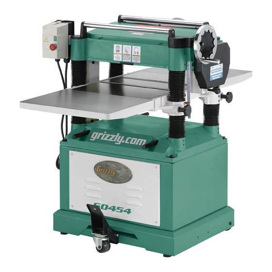
- Page 12 15" & 20" MOBILE PLANERS OWNER'S MANUAL Model G0454 Shown COPYRIGHT © MAY, 2005 BY GRIZZLY INDUSTRIAL, INC., REVISED NOVEMBER, 2012 (TS) WARNING: NO PORTION OF THIS MANUAL MAY BE REPRODUCED IN ANY SHAPE OR FORM WITHOUT THE WRITTEN APPROVAL OF GRIZZLY INDUSTRIAL, INC.
- Page 13 This manual provides critical safety instructions on the proper setup, operation, maintenance, and service of this machine/tool. Save this document, refer to it often, and use it to instruct other operators. Failure to read, understand and follow the instructions in this manual may result in fire or serious personal injury—including amputation, electrocution, or death.
-
Page 14: Table Of Contents
Machine Description ........2 Cleaning & Protecting ........30 Identification ........... 3 Lubrication ........... 31 Internal Components........4 G0453 Machine Data Sheet ......5 SECTION 7: SERVICE ........33 G0454 Machine Data Sheet ......7 Troubleshooting ........... 33 Setting/Replacing Knives ......36 SECTION 1: SAFETY ........ -
Page 15: Introduction
Machine Description and it helps us determine if updated documenta- tion is available for your machine. The Model G0453/G0454 Planer is designed to remove material in precise increments from the surface of natural wood fiber stock to make the workpiece flat. -
Page 16: Identification
Magnetic Rollers Gearbox Handwheel ON/OFF Switch Rear Extension Wing Feed Rate V-Belt Control Knob Cover Bed Rollers Front Table Extension Locks Wing Lifting (1 of 4) Cabinet Access Locking Panel Foot Pedal Figure 1. General identification. G0453/G0454 (Mfg. Since 3/08) -
Page 17: Internal Components
Use this machine with respect and caution to decrease the risk of operator injury. If normal safety precautions are overlooked or ignored, serious personal injury may occur. G0453/G0454 (Mfg. Since 3/08) -
Page 18: G0453 Machine Data Sheet
G0453 Machine Data Sheet MACHINE DATA SHEET Customer Service #: (570) 546-9663 · To Order Call: (800) 523-4777 · Fax #: (800) 438-5901 MODEL G0453 15" PLANER data sheet Product Dimensions: Weight................................655 lbs. Width (side-to-side) x Depth (front-to-back) x Height............... 32-1/2 x 42 x 45-7/8 in. - Page 19 The information contained herein is deemed accurate as of 5/15/2017 and represents our most recent product specifications. Model G0453 PAGE 2 OF 3 Due to our ongoing improvement efforts, this information may not accurately describe items previously purchased. G0453/G0454 (Mfg. Since 3/08)
-
Page 20: G0454 Machine Data Sheet
The information contained herein is deemed accurate as of 5/15/2017 and represents our most recent product specifications. Model G0454 PAGE 1 OF 3 Due to our ongoing improvement efforts, this information may not accurately describe items previously purchased. G0453/G0454 (Mfg. Since 3/08) - Page 21 The information contained herein is deemed accurate as of 5/15/2017 and represents our most recent product specifications. Model G0454 PAGE 2 OF 3 Due to our ongoing improvement efforts, this information may not accurately describe items previously purchased. G0453/G0454 (Mfg. Since 3/08)
-
Page 22: Section 1: Safety
Everyday ery. Never operate under the influence of drugs or eyeglasses are NOT approved safety glasses. alcohol, when tired, or when distracted. G0453/G0454 (Mfg. Since 3/08) - Page 23 EXPERIENCING DIFFICULTIES. If at any time debris. Make sure they are properly installed, you experience difficulties performing the intend- undamaged, and working correctly BEFORE ed operation, stop using the machine! Contact our operating machine. Technical Support at (570) 546-9663. -10- G0453/G0454 (Mfg. Since 3/08)
-
Page 24: Additional Safety Instructions For Planers
Use this and other machin- ery with caution and respect. Failure to do so could result in serious personal injury, damage to equipment, or poor work results. -11- G0453/G0454 (Mfg. Since 3/08) -
Page 25: Section 2: Power Supply
SECTION 2: POWER SUPPLY Availability G0453 220V Circuit Requirements Before installing the machine, consider the avail- This machine is prewired to operate on a power ability and proximity of the required power supply supply circuit that has a verified ground and meets circuit. -
Page 26: Grounding Instructions
Current Carrying Prongs and matching plug/receptacle. Additionally, it must Figure 4. Typical L6-30 plug and receptacle. meet the following size requirements: G0453 Minimum Gauge Size ....12 AWG NOTICE G0454 Minimum Gauge Size ....10 AWG Maximum Length (Shorter is Better)..50 ft. -
Page 27: Section 3: Setup
Wear safety glasses during • 4" or 5" Dust Hose w/Clamps ..... 1 the entire setup process! Unpacking The Model G0453/G0454 is a heavy machine. Serious Your machine was carefully packaged for safe personal injury may occur transportation. Remove the packaging materials if safe moving methods are from around your machine and inspect it. -
Page 28: Inventory
C. Foot Pedal ..........1 D. Handwheel ..........1 E. Caster ............1 Extension Wings ........2 G0453 Hardware and Tools (not shown) • Set Screws M8-1.25 x 20 (Wings) ....4 • Hex Bolts M8-1.25 x 30 (Wings) ....6 •... -
Page 29: Cleanup
Repeat Steps 2–3 as necessary until clean, then coat all unpainted surfaces with a quality metal protectant to prevent rust. -16- G0453/G0454 (Mfg. Since 3/08) -
Page 30: Site Considerations
Model G0453 X = 42" Y = 28" Model G0454 X = 55 ⁄ " Y = 36 ⁄ " Dust Feed Direction Port Figure 6. Minimum working clearances. -17- G0453/G0454 (Mfg. Since 3/08) -
Page 31: Lifting & Moving Base Unit
Set Screws machine from the crate. The cabinet stand on the Model G0453/G0454 planer is equipped with four lifting bars that pull out in order to lift and place the planer, as shown Figure 8. Front extension wing installed (Model in Figure 7. - Page 32 Figure 11. Attaching magnetic switch. Figure 9. Installing the table height handwheel. NOTICE Model G0453: Attach the dust hood to the top of the planer with the M6-1 x 10 hex bolts, Before starting your machine, you must 6mm flat washers, and M6-1 hex nuts as...
- Page 33 13. Remove the pin and hex bolt that are already mounted in the foot pedal bracket. Bracket 14. Align the caster assembly with the mounting Caster Foot Pedal holes in the foot pedal bracket. Figure 13. Foot pedal and caster installed. -20- G0453/G0454 (Mfg. Since 3/08)
-
Page 34: Dust Collection
Once the assembly is complete, test run your machine to make sure it runs properly and is ready for regular operation. The test run consists DO NOT operate the Model G0453/G0454 of verifying the following: 1) The motor powers up without an adequate dust collection system. -
Page 35: Re-Tension V-Belts
The OFF button Roller spring tension (Page 43). • safety feature is not working correctly. This safety feature must work properly before Chip deflector positioning (Page 43). • proceeding with regular operations. Call Tech Support for help. -22- G0453/G0454 (Mfg. Since 3/08) -
Page 36: Section 4: Operations
Stands to one side of the planer path to Regardless of the content in this section, reduce the risk of kickback injuries, then, with Grizzly Industrial will not be held liable for the flat surface of the workpiece facing down, accidents caused by lack of training. -
Page 37: Planing Tips
Minor Cupping: Workpieces with slight cup- ping can be safely supported if the cupped side is facing the table. On the contrary, a workpiece supported on the bowed side will rock during operation and could cause severe injury from kickback. -24- G0453/G0454 (Mfg. Since 3/08) -
Page 38: Wood Hardness
• Push the knob in to use the high feed rate (30 FPM for Model G0453, and 20 FPM for Model G0454). Janka Species Hardness •... -
Page 39: Depth Of Cut
Rotacator is not available, a straightedge and feel- Height er gauges can be used, but care must be taken to Handwheel achieve accurate results. Depth of Cut Indicator & Scale Figure 17. Depth of cut indicator and scale. -26- G0453/G0454 (Mfg. Since 3/08) - Page 40 Lower the table all the way to give yourself room to work. Loosen the set screws above each of the four roller adjustment hex bolts (see Figure 19). Set Screws Adjustment Hex Bolts Figure 19. Bed roller height controls. -27- G0453/G0454 (Mfg. Since 3/08)
-
Page 41: Section 5: Accessories
Features a heavy-duty ⁄ HP 110V motor, Refer to the newest copy of the Grizzly knife holding angle adjustable from 20° to 70°, Catalog for other accessories available for and adjustable-height 120 grit grinding wheel. - Page 42 ® H3788—G96 Gun Treatment 12 oz Spray ® H3789—G96 Gun Treatment 4.5 oz Spray ® Figure 24. SHOP FOX Roller Table. ® Figure 26. Recommended products for protect- ing unpainted cast iron/steel part on machinery. -29- G0453/G0454 (Mfg. Since 3/08)
-
Page 43: Section 6: Maintenance
Page 29 for more details). • Check/repair/replace worn or damaged wires. • Resolve any other unsafe condition. Every 40 Hours of Operation: • Clean cutterhead and check knife height (Page 36). • Lubricate table columns and leadscrews (Page 31). -30- G0453/G0454 (Mfg. Since 3/08) -
Page 44: Lubrication
The bearings are standard sizes and can be replaced through Grizzly (refer to the Parts Column Dust Breakdowns beginning on Page 49 for bearing Sleeve identification). - Page 45 Use shop rags and mineral spirits to clean away Fill Plug any debris and grime, then brush on a light coat of multi-purpose grease to the chain and sprockets. Figure 33. Gearbox fill plug. Figure 31. Drive chain and sprockets. -32- G0453/G0454 (Mfg. Since 3/08)
-
Page 46: Section 7: Service
4. V-belt(s) worn or loose. 4. Inspect/replace belts with a new matched set. 5. Pulley loose. 5. Realign/replace shaft, pulley, setscrew, and key. 6. Motor mount loose/broken. 6. Tighten/replace. 7. Machine incorrectly mounted. 7. Tighten mounting bolts; relocate/shim machine. -33- G0453/G0454 (Mfg. Since 3/08) - Page 47 3. Feed rate too fast. 4. Depth of cut too deep. 4. Reduce the depth of cut (Page 26). 5. Misaligned chip breaker. 5. Adjust both sides of chip breaker to the correct height (Page 40). -34- G0453/G0454 (Mfg. Since 3/08)
- Page 48 3. Depth of cut too shallow. Inconsistent chip 1. Chips are not being properly expelled from 1. Use an adequate dust collection system; adjust the marks. around the cutterhead. chip deflector in or out, depending upon your setup (Page 43). -35- G0453/G0454 (Mfg. Since 3/08)
-
Page 49: Setting/Replacing Knives
Gib Bolt e parallelism The knife gauge that is included with the Model Figure 34. Cutterhead components (G0454 G0453/G0454 is designed to set the knives cutterhead shown). 0.059" higher than the cutterhead surface. If you have not already done so, loosen... -
Page 50: V-Belt Tensioning/Replacement
V-Belt Tensioning/ Jack Screws (G0453 & G0454): Insert the hex wrench into the jack screws through Replacement the access holes in the cutterhead (see Figure 36). Rotate the jack screws to raise or lower the knife until it barely touches the... - Page 51 When the V-belts are correctly tensioned, make sure the motor mount hex nuts are tight, then replace the cabinet cover and the belt cover. Figure 39. Front cabinet cover removed to expose the motor. -38- G0453/G0454 (Mfg. Since 3/08)
-
Page 52: Table Height Chain Tension
Remove the front and rear cabinet panels to gain access to the chain system, as shown in Figure 41. Idler Sprocket Lock Bolts Figure 41. Table height idler sprocket and lock bolts (viewed from underneath the planer base). -39- G0453/G0454 (Mfg. Since 3/08) -
Page 53: Feed Rollers, Chip Breaker & Pressure Bar Heights
C. Pressure Bar........0.008" D. Outfeed Roller ........0.020" call out components (Bottom Dead Center) Figure 43. Using a Rotacator to find BDC. A & B Figure 42. Planer component recommended clearances (illustration is not to scale). -40- G0453/G0454 (Mfg. Since 3/08) - Page 54 Rotacator dial from Step 5, repeat Steps 7–10 for the outfeed roller, but adjust it until 14. Re-install the belt cover, top cover, and the it is 0.020" below the BDC of the cutterhead dust hood. knife. -41- G0453/G0454 (Mfg. Since 3/08)
- Page 55 (refer to Bed Roller Height on Page 26 for detailed instructions). Place the wood blocks along the sides of the table, as illustrated in Figure 47. 36" Figure 47. Wood blocks properly positioned on the planer table. -42- G0453/G0454 (Mfg. Since 3/08)
-
Page 56: Roller Spring Tension
#4 so that it protrudes ⁄ " above the head casting (see Figure 48). Figure 49. Chip deflector and securing hex bolts. Cap Screw #4 Cap Screws #1–#3 Figure 48. Roller spring tension adjustment cap screws. -43- G0453/G0454 (Mfg. Since 3/08) -
Page 57: Scale Calibration
Scale planer. DO NOT operate the planer if the & Pointer anti-kickback fingers are not operating cor- rectly. Failure to heed this warning could result in serious personal injury. Figure 50. Table height scale. -44- G0453/G0454 (Mfg. Since 3/08) -
Page 58: Pulley Alignment
DISCONNECT PLANER FROM POWER! Remove both cabinet covers and the belt cover, then use the straightedge to check pul- ley alignment, as shown in Figure 52. Figure 52. Checking pulley alignment. -45- G0453/G0454 (Mfg. Since 3/08) -
Page 59: Section 8: Wiring
Technical Support at (570) 546-9663. The photos and diagrams included in this section are best viewed in color. You can view these pages in color at www.grizzly.com. -46- G0453/G0454 (Mfg. Since 3/08) -
Page 60: G0453 Wiring Diagram
Always use the wiring diagram inside the motor junction box. NEMA 6-20 Plug (As Recommended) Ground Motor Grnd Start Capacitor 200MFD 250VAC Run Capacitor 20MFD 400VAC READ ELECTRICAL SAFETY G0453/G0454 (Mfg. Since 3/08) -47- ON PAGE 46! -
Page 61: G0454 Wiring Diagram
Always use the wiring diagram inside the motor junction box. NEMA L6-30 Plug (As Recommended) Ground Motor Grnd Start Capacitor 300MFD 250VAC Run Capacitor 60MFD 400VAC READ ELECTRICAL SAFETY -48- G0453/G0454 (Mfg. Since 3/08) ON PAGE 46! -
Page 62: Section 9: Parts
SECTION 9: PARTS G0453 Headstock Breakdown -49- G0453/G0454 (Mfg. Since 3/08) - Page 63 G0453 Headstock Parts List REF PART # DESCRIPTION PART # DESCRIPTION P0453001 COGGED V-BELT MX-60 P0453058 FLANGE BOLT M6-1 X 10 P0453002 OIL FILL LABEL P0453059 TOP COVER P0453003 CHAIN 06B-1 X 49 31LINKS P0453060 FLAT HD SCR M6-1 X 8...
-
Page 64: G0453 Table
FLAT WASHER 8MM P0453212 SET SCREW M6-1 X 16 P0453206 LOCK WASHER 8MM P0453213 ECCENTRIC SHAFT P0453207 TABLE EXTENSION WING P0453214 BALL BEARING 608ZZ P0453208 STAR KNOB M12-1.75 P0453215 BED ROLLER P0453209 LOCK BOLT P0453216 MAIN TABLE -51- G0453/G0454 (Mfg. Since 3/08) -
Page 65: G0453 Columns
P0453329 SECONDARY COLUMN P0453315 SPROCKET P0453330 FLAT WASHER 12MM P0453316 EXT RETAINING RING 12MM P0453331 HEX NUT M12-1.75 P0453317 KEY 4 X 4 X 12 P0453332 HEX BOLT M12-1.75 X 45 P0453318 GEAR P0453333 BASE -52- G0453/G0454 (Mfg. Since 3/08) -
Page 66: G0453 Cabinet Stand
G0453 Cabinet Stand Breakdown For Machine Manufacture Date For Machine Manufacture Date Prior to 03/08 of 03/08 or After 430-1 430A-1 430-3 430-6 430A-6 430-4 430A-5 430-2 430A-2 430-5 430A-4 430A 437-1 448A -53- G0453/G0454 (Mfg. Since 3/08) - Page 67 G0453 Cabinet Stand Parts List PART # DESCRIPTION PART # DESCRIPTION P0453401 RUBBER FOOT 430A-2 P0453430A-2 MOTOR FAN V2.03.08 401-1 P0453401-1 HEX NUT 3/8-16 430A-4 P0453430A-4 R CAPACITOR 20M 400V V2.03.08 P0453402 PLASTIC GROMMET 430A-5 P0453430A-5 S CAPACITOR 200M 250V V2.03.08...
-
Page 68: G0453 Gearbox
CAP SCREW M8-1.25 X 50 P0453518 BALL BEARING 6201ZZ P0453540 GEARBOX COVER P0453519 STEEL BALL 4MM P0453541 FLANGE BOLT M6-1 X 12 P0453520 COMPRESSION SPRING P0453542 CHAIN 06B-1 X 49 P0453521 KEY 5 X 5 X 50 -55- G0453/G0454 (Mfg. Since 3/08) -
Page 69: G0453 Label Placement
MUST maintain the original location and readability of the labels on the machine. If any label is removed or becomes unreadable, REPLACE that label before using the machine again. Contact Grizzly at (800) 523-4777 or www.grizzly.com to order new labels. -56-... -
Page 70: G0454 Headstock
G0454 Headstock Breakdown -57- G0453/G0454 (Mfg. Since 3/08) - Page 71 P0454088 OUTFEED ROLLER SPROCKET P0454044 WORM GEAR P0454089 OUTFEED ROLLER P0454045 BALL BEARING 6201ZZ P0454090 HEX BOLT M6-1 X 16 P0454046 INT RETAINING RING 32MM P0454091 FLAT WASHER 6MM P0454047 CAP SCREW M5-.8 X 55 -58- G0453/G0454 (Mfg. Since 3/08)
- Page 72 KEY 8 X 8 X 35 P0454116 CUTTERHEAD 20" 4-KNIFE 105A P0454105A MOTOR PULLEY MX V2.09.07 P0454117 HEAD CASTING POWER CORD 12G 3W 72" L6-30P V2.08.12 105-1 P0454105-1 MOTOR PULLEY WASHER 124V2 P0454124V2 105-2 P0454105-2 TAPERED HEAD SCREW -59- G0453/G0454 (Mfg. Since 3/08)
-
Page 73: G0454 Table
SET SCREW M6-1 X 12 P0454203 LOCK WASHER 8MM P0454210 ECCENTRIC SHAFT P0454204 EXTENSION WING P0454211 BALL BEARING 6201ZZ P0454205 STAR KNOB M12-1.75 P0454212 BED ROLLER P0454206 LOCK ROD P0454213 MAIN TABLE P0454207 P0454214 SET SCREW M8-1.25 X 20 -60- G0453/G0454 (Mfg. Since 3/08) -
Page 74: G0454 Columns
SECONDARY COLUMN P0454316 FLAT WASHER 10MM P0454333 FLAT WASHER 12MM P0454317 KEY 5 X 5 X 16 P0454334 HEX NUT M12-1.75 P0454318 SPROCKET P0454335 HEX BOLT M12-1.75 X 60 P0454319 EXT RETAINING RING 12MM P0454336 BASE -61- G0453/G0454 (Mfg. Since 3/08) -
Page 75: G0454 Cabinet Stand
G0454 Cabinet Stand Breakdown 429-1 429-4 429-2 429-5 429-6 440A -62- G0453/G0454 (Mfg. Since 3/08) - Page 76 HEX NUT M8-1.25 P0454444 HEX NUT M10-1.5 P0454428 FLAT WASHER 8MM P0454447 KEY 5 X 5 X 30 P0454429 MOTOR 5HP 240V 1-PH P0454542 PEDAL ASSEMBLY 429-1 P0454429-1 MOTOR FAN COVER P0454546 PLATE CONNECTING ROD -63- G0453/G0454 (Mfg. Since 3/08)
-
Page 77: G0454 Gearbox
OIL SEAL 20 X 35 X 7 P0454539 FLANGE COVER P0454518 BALL BEARING 6204ZZ P0454540 CAP SCREW M8-1.25 X 50 P0454519 BALL BEARING 6201ZZ P0454541 GEARBOX COVER P0454520 STEEL BALL 4MM P0454543 FLANGE BOLT M6-1 X 12 P0454521 COMPRESSION SPRING -64- G0453/G0454 (Mfg. Since 3/08) -
Page 78: G0454 Label Placement
MUST maintain the original location and readability of the labels on the machine. If any label is removed or becomes unreadable, REPLACE that label before using the machine again. Contact Grizzly at (800) 523-4777 or www.grizzly.com to order new labels. -65-... - Page 79 -66- G0453/G0454 (Mfg. Since 3/08)
-
Page 80: Warranty Card
Would you recommend Grizzly Industrial to a friend? _____ Yes _____No Would you allow us to use your name as a reference for Grizzly customers in your area? Note: We never use names more than 3 times. _____ Yes _____No 10. - Page 81 FOLD ALONG DOTTED LINE Place Stamp Here GRIZZLY INDUSTRIAL, INC. P.O. BOX 2069 BELLINGHAM, WA 98227-2069 FOLD ALONG DOTTED LINE Send a Grizzly Catalog to a friend: Name_______________________________ Street_______________________________ City______________State______Zip______ TAPE ALONG EDGES--PLEASE DO NOT STAPLE...
-
Page 82: Warranty And Returns
WARRANTY AND RETURNS Grizzly Industrial, Inc. warrants every product it sells for a period of 1 year to the original purchaser from the date of purchase. This warranty does not apply to defects due directly or indirectly to misuse, abuse, negligence, accidents, repairs or alterations or lack of maintenance.