Advertisement
Quick Links
Download this manual
See also:
User Manual
Advertisement

Related Manuals for GE IC755CxS06RDx


Summary of Contents for GE IC755CxS06RDx
- Page 1 Automation & Controls Operator Interface Products QuickPanel Operator Interface IC755CxS06RDx (6” Display) IC755CxW07CDx (7” Display) IC755CxS10CDx (10” Display) IC755CxS12CDx (12” Display) IC755CxS15CDx (15” Display) Quick Start Guide, GFK-2893K Dec 2015...
-
Page 2: Safety Symbol Legend
Safety Symbol Legend Indicates a procedure, condition, or statement that, if not strictly observed, could result in personal injury or death. Warning Indicates a procedure, condition, or statement that, if not strictly observed, could result in damage to or destruction of equipment. -
Page 3: Physical Characteristics
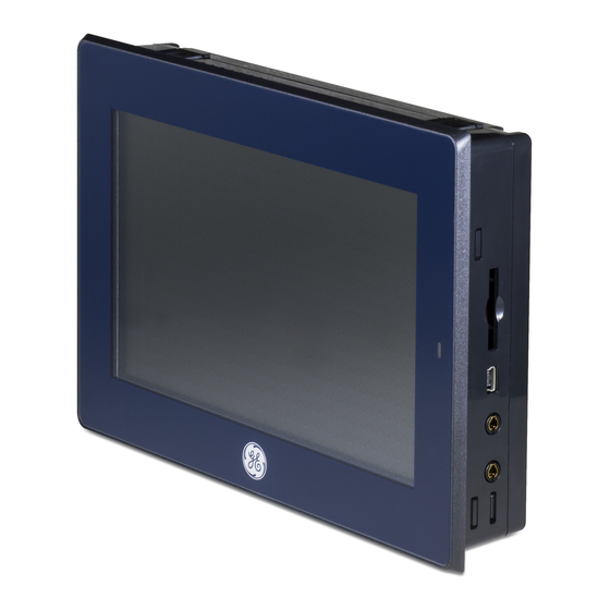
Input Power 183.50 mm (7.22 in) 75 mm (2.95 in) Battery Cover License Label Effective Screw Depth 6 mm (0.24 in) Product Nameplate IC755CxS06RDx Profile and Hardware Features Note: Refer to the table IC755CxW06CDx Specifications for drawing dimensions. GFK-2893K QuickPanel... - Page 4 Status SD Card Indicator LED MICRO USB Touchscreen LINE OUT MIC IN Input USB Host Power Ports Battery Cover IC755CxW07CDx Profile and Hardware Features Note: Refer to the table IC755CxW07CDx Specifications for drawing dimensions. QuickPanel Quick Start Guide GFK-2893K...
- Page 5 SD Card Status Indicator LED Touchscreen Input LAN1 MICRO COM1 LINE LAN2 COM2 Power Host Ports IC755CxS10CDx Profile and Hardware Features Note: Refer to the table IC755CxS10CDx Specifications for drawing dimensions. GFK-2893K QuickPanel Quick Start Guide...
- Page 6 IC755CxS12CDx Profile and Hardware Features Note: Refer to the table IC755CxS12CDx Specifications for drawing dimensions. QuickPanel Quick Start Guide GFK-2893K...
- Page 7 SD Card Status Indicator Touchscreen Input LINE LAN2 LAN1 MICRO COM2 COM1 Power Host Ports IC755CxS15CDx Profile and Hardware Features Note: Refer to the table IC755CxS15CDx Specifications for drawing dimensions. GFK-2893K QuickPanel Quick Start Guide...
-
Page 8: Specifications
Specifications 2.1 Physical Specifications and Mounting Options IC755CxS06RDx Specifications Item Specification Freescale i.MX535 Processor (1 GHz ARM Cortex A8) DDR3 SDRAM 512 MB Memory NAND FLASH 256 MB SRAM 512 KB (with battery backup) Microsoft Windows Operating System Embedded Compact 7 Type 5.7”... - Page 9 IC755CxW07CDx Specifications Item Specification Freescale i.MX535 Processor (1 GHz ARM Cortex A8) DDR2 SDRAM 512 MB Memory SLC NAND 256 MB SRAM 512 KB (with battery backup) Microsoft Windows Operating System Embedded Compact 7 Type 7” Widescreen TFT LCD Resolution 800(W) x 480(H) pixels WVGA Display Color...
- Page 10 IC755CxS10CDx Specifications Item Specification Freescale i.MX535 Processor (1 GHz ARM Cortex A8) DDR3 SDRAM 1 GB Memory SLC NAND 512 MB SRAM 512 KB (with battery backup) Microsoft Windows Operating System Embedded Compact 7 Type 10.5” Standard TFT LCD Resolution 800(W) x 600(H) pixels SVGA Display Color...
- Page 11 IC755CxS12CDx Specifications Item Specification Freescale i.MX535 Processor (1 GHz ARM Cortex A8) DDR3 SDRAM 1 GB Memory SLC NAND 512 MB SRAM 512 KB (with battery backup) Microsoft Windows Operating System Embedded Compact 7 Type 12.1” Standard TFT LCD Resolution 800(W) x 600(H) pixels SVGA Display Color...
- Page 12 IC755CxS15CDx Specifications Item Specification Freescale i.MX535 Processor (1 GHz ARM Cortex A8) DDR3 SDRAM 1 GB Memory SLC NAND 512 MB SRAM 512 KB (with battery backup) Microsoft Windows Operating System Embedded Compact 7 Type 15” Standard TFT LCD Resolution 1024(W) x 768(H) pixels XGA Display Color...
-
Page 13: Environmental Specifications
800~1114 hPa, altitude up to 2000 m Altitude (6561.68 ft) Compliant with EU RoHS Directive RoHS 2011/65/EU IC755CxS06RDx: UL Type 4X; IP65 in panel mount only IC755CxW07CDx: UL Type 4X; IP65 in panel mount only IC755CxS10CDx: UL Type 4X; Enclosure Rating IP65 in panel mount only IC755CxS12CDx: UL Type 4X;... -
Page 14: Initial Startup
Initial Startup Note: For installation requirements, complete installation procedures, and operating information, refer to the QuickPanel Operator Interface User Manual (GFK-2847). You will need the following: A Safety Extra Low Voltage (SELV) and Limited Energy Circuit or SELV and Class 2 dc power supply. - Page 15 3.1 QuickPanel Battery Installation Installing the battery should only be performed by trained personnel and in a non- hazardous location. If the QuickPanel is VESA mounted, detach from the VESA arm when replacing the battery. Refer to the section, Mounting on a VESA arm.
- Page 16 To install the battery Remove the battery cover by pressing down while sliding outward. IC755CxS06RDx Battery Cover Removal Connect the battery harness connector to the header, noting keyed orientation. IC755CxS06RDx Battery Harness Connection Verify that positive (red) is down and negative (black) is up.
- Page 17 Use of batteries not specified for use with the QuickPanel product may present a risk of fire or explosion. Warning Replace the battery for the IC755CxS06RDx only with GE battery part number IC755ACCBATT. Caution Replace the battery for the IC755CxW07CDx only with GE battery part number IC755ACCBATT.
- Page 18 3.3 Connecting Input Power To connect input power Verify that the power cable is not energized. M2.5 Loosen the Mounting clamps screw clamps Screw clamps on the mating power connector. Strip the insulation from the power +24 V dc cables.
- Page 19 3.4 LED Indicators 3.4.1 Operation Status LEDs The QuickPanel has one tri-color LED that provides visual operation status indication for the IC755CxS06RDx, IC755CxW07CDx, and IC755CxSxxCDx units. LED State QuickPanel State Amber, solid Operating system starting Green, solid Normal operating state...
-
Page 20: Mounting And Installation
4. Mounting and Installation 4.1 Protective Sheet Installation To install the protective sheet Remove the protective film from the QuickPanel display screen. Wipe the display unit of any dust or fingerprints. Peel back a corner of the clear side of the protective sheet. - Page 21 4.2 Mounting Location When mounting the QuickPanel Operator Interface, make sure the mounting area allows room to insert and remove the SD card, cables, and mounting brackets. Select a location that allows natural convection air flow from bottom to top of the QuickPanel enclosure.
- Page 22 • One #2 Phillips head screwdriver • Mounting brackets (supplied) The mounting holes for the IC755CxS06RDx, IC755CxW07CDx, and IC755CxS10CDx are located on the top and bottom sides of the unit. IC755CxS06RDx Mounting Holes IC755CxW07CDx Mounting Holes...
- Page 23 IC755CxS10CDx Mounting Holes The IC755CxS12CDx and IC755CxS15CDx mounting holes are located on the top, bottom, and sides of the unit. IC755CxS12CDx Mounting Holes IC755CxS15CDx Mounting Holes GFK-2893K QuickPanel Quick Start Guide...
- Page 24 +0.50, -0.00 mm (+0.02, -0.00 in). 183.50 mm (7.22 in) Panel Thickness: 1.0 to 5.0 mm (0.04 to 0.20 in) IC755CxS06RDx Panel Cutout Dimensions 183.50 mm (7.22 in) Panel Thickness: 1.0 to 5.0 mm (0.04 to 0.20 in) IC755CxW07CDx Panel Cutout Dimensions...
- Page 25 266 mm (10.47 in) Panel Thickness: 1.6 to 5.0 mm (0.06 to 0.20 in) IC755CxS10CDx Panel Cutout Dimensions 302 mm (11.89 in) Panel Thickness: 1.6 to 5.0 mm (0.06 to 0.20 in) IC755CxS12CDx Panel Cutout Dimensions 379 mm (14.92 in) Panel Thickness: 1.6 to 5.0 mm (0.06 to 0.20 in)
- Page 26 Tighten the screws on the mounting bracket in a clock-wise direction. Torque Range for Mounting Clamp Screws Display Unit Torque Range IC755CxS06RDx 0.3 Nm (2.66 in-lb) IC755CxW07CDx 0.3 Nm (2.66 in-lb) IC755CxS10CDx 0.7 Nm (6 in-lb) IC755CxS12CDx 1.0 to 1.2 Nm (8.9 to 10.6 in-lb)
- Page 27 (displayed in the following figures). The mounting holes for IC755CxS06RDx and IC755CxW07CDx attach with M4 screws that are 6 mm (0.24 in) or less in length. The mounting holes for IC755CxSxxCDx mounting holes attach with M4 screws that are 8 mm (0.32 in) or less in length.
- Page 28 75 mm (2.95 in) IC755CxW07CDx or IC755CxS06RDx VESA Mounting Holes 100 mm 100 mm (3.94 in) IC755CxSxxCDx VESA Mounting Holes Note: For user manuals, product updates, and other information, go to the Support website, http://www.ge-ip.com/support and refer to Operator Interfaces and PC.
- Page 29 4.6 Connectors 4.6.1 Power Connector Details Pin # Signal Name Pin-out † +24 V dc † IC755CxSxxCDA supports both +12 V dc or +24 V dc IN 4.6.2 Ethernet Port Details Interface: Ethernet 10BASE-T/100BASE-TX Pin # Signal Name Pin-out 4.6.3 USB Host Port Details Interface: 2x USB 2.0 Pin # Signal Name...
- Page 30 4.6.4 Serial Port Details 4.6.4.1 IC755CxS06RDx 4.6.4.1.1 Serial Port COM1 Interface: RS-232 Pin # Signal Name SGND Pin 5 Pin 1 IC755CxS06RDx Serial Port COM1 Pin-out QuickPanel Quick Start Guide GFK-2893K...
- Page 31 4.6.4.2 IC755CxW07CDx Interface: x1 RS-232 Signal Name Pin # SGND Pin 1 Pin 5 IC755CxW07CDx Serial Port COM1 Pin-out GFK-2893K QuickPanel Quick Start Guide...
- Page 32 4.6.4.3 IC755CxSxxCDx 4.6.4.3.1 Serial Port COM1 Interface: RS-232 Pin # Signal Name SGND C755CxSxxCDx Serial Port COM1 Pin-out QuickPanel Quick Start Guide GFK-2893K...
-
Page 33: Serial Port Com2
4.6.4.3.2 Serial Port COM2 Interface: RS-232C/485 (default is RS-485 Half-duplex) RS-232 RS-485 Pin # Signal Name Signal Name Signal † † Name (Full-duplex (Half-duplex ‡ TXD+ DATA+ ‡ TXD- DATA- ‡ RXD+ DATA+ ‡ RXD- DATA- SGND † Full-duplex RS–485 is backwards compatible to RS–422 mode. - Page 34 5. Product Certifications and Installation Guidelines for Conformance The QuickPanel Operator Interface is intended for use in industrial environments and, when properly installed, shall comply with the following agency approvals. 5.1 Agency Approvals Note: The agency approvals listed in the following table and on the Declaration of Conformities are believed to be accurate;...
- Page 35 Electromagnetic Compatibility Directive Self-declaration in accordance with European Directives European Electromagnetic EN61000-6-2, Compatibility (EMC) for Industrial Control EN61000-6-4 Equipment Det Norske Veritas (DNV) certification only applies to Maritime Society QuickPanel 7'' Display Certification marking unit (part number IC755CSW07CDACA) 5.2 Conditions of Safe Use for Installation in Hazardous Locations The following information applies to products bearing the UL marking for Hazardous areas and the ATEX...
- Page 36 The equipment shall be installed in an enclosure that provides a minimum ingress protection of IP 54 in accordance with IEC 60079-0. Transient protection shall be provided that is set at a level not exceeding 140% of the peak rated voltage value at the supply terminals to the equipment.
- Page 37 EXPLOSION HAZARD - Do not connect or disconnect equipment power, communication, audio, or battery unless power has been removed or the area is known to be non-hazardous. EXPLOSION HAZARD - Substitution of components may impair suitability. EXPLOSION HAZARD - Warning DO NOT VESA-MOUNT.
- Page 38 Changes or modifications to this unit that are not expressly approved by GE Intelligent Platforms could void the user’s authority to operate the equipment. Industry Canada requires the following note to be...
- Page 39 5.4 EMC Installation and Operation Considerations This equipment is intended for industrial use only and complies with a minimum level of EMC performance as defined by EN 61000-6-2 and EN 61000-6-4 standards. To meet these requirements, the following installation and operation considerations were taken into account: •...
- Page 40 GE Intelligent Platforms Contact Information If you purchased this product through an Authorized Channel Partner, contact the seller directly. General Contact Information Online technical support and http://support.ge-ip.com GlobalCare Additional information http://www.ge-ip.com/ Solution Provider solutionprovider.ip@ge.com Technical Support If you have technical problems that cannot be resolved with the...
- Page 41 Customer Care Email customercare.cn.ip@ge.com (China) www.ge-ip.com Copyright © 2014 - 2015 GE Automation & Controls, Inc. All Rights Reserved *Trademark of GE Automation & Controls, Inc. All other brands or names are property of their respective holders. GFK-2893K...