Table of Contents
Advertisement
GE
Intelligent Platforms
Operator Interface Products
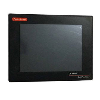
15" QuickPanel* View
& QuickPanel Control
Loaded Color TFT
IC754CSF15CTD, IC754CBF15CTD, IC754CGF15CTD
IC754VBF15CTDEX, IC754VGF15CTDEX, IC754VSF15CTDEX
IC754VSF15CTD, IC754VBF15CTD, IC754VGF15CTD
IC754CBF15CTDEX, IC754CGF15CTDEX, IC754CSF15CTDEX
Hardware User'sGuide, GFK-2402D
December 2011
Advertisement
Table of Contents

Related Manuals for GE IC754CSF15CTD


Summary of Contents for GE IC754CSF15CTD
- Page 1 Intelligent Platforms Operator Interface Products 15" QuickPanel* View & QuickPanel Control Loaded Color TFT IC754CSF15CTD, IC754CBF15CTD, IC754CGF15CTD IC754VBF15CTDEX, IC754VGF15CTDEX, IC754VSF15CTDEX IC754VSF15CTD, IC754VBF15CTD, IC754VGF15CTD IC754CBF15CTDEX, IC754CGF15CTDEX, IC754CSF15CTDEX Hardware User'sGuide, GFK-2402D December 2011...
- Page 2 Features may be described herein which are not present in all hardware and software systems. GE Intelligent Platforms assumes no obligation of notice to holders of this document with respect to changes subsequently made.
- Page 3 Contact Information If you purchased this product through an Authorized Channel Partner, please contact the seller directly. General Contact Information Online technical support and GlobalCare www.ge-ip.com/support Additional information http://www.ge-ip.com/ Solution Provider solutionprovider.ip@ge.com Technical Support If you have technical problems that cannot be resolved with the information in this guide, please contact us by te or email, or on the web at www.ge-ip.com/support...
- Page 5 Notices GE Intelligent Platforms reserves the right to make improvements to the products described in this publication at any time and without notice. QuickPanel, QuickPanel View, and QuickPanel Control are trademarks of GE Intelligent Platforms in the United States and other countries. Any other trademarks referenced herein are the property of their respective owners and used solely for purposes of identifying compatibility with the products of GE Intelligent Platforms.
- Page 6 Notices The following statements are required to appear for Class I Division/Zone 2 Hazardous Areas. WARNING – EXPLOSION HAZARD – SUBSTITUTION OF COMPONENTS MAY IMPAIR SUITABILITY FOR CLASS 1, DIVISION 2. WARNING - EXPLOSION HAZARD - WHEN IN HAZARDOUS LOCATIONS, TURN OFF POWER BEFORE REPLACING OR WIRING MODULES.
-
Page 7: Table Of Contents
Contents Welcome ....................1-1 Getting Started ..................... 1-2 Firmware Updates ..................1-4 Overview ....................2-1 QuickPanel View/Control Hardware............. 2-2 QuickPanel View/Control Software .............. 2-5 Installation ....................3-1 Conditions of Safe Use ................3-1 Considerations for Choosing a Mounting Location ........3-2 Panel Cutout .................... - Page 8 Contents Environmental ....................A-5 Battery ......................A-5 Calendar/Clock..................... A-5 Agency Approvals ..................A-6 Diagnostics ................... B-1 Power up ...................... B-1 Pocket Internet Explorer ................B-1 Physical Unit ....................B-2 15" QuickPanel* View & QuickPanel Control Loaded Color TFT –December 2011 GFK-2402D...
-
Page 9: Welcome
Chapter Welcome Congratulations on your purchase of a QuickPanel View/Control, the most advanced compact control computer available. The QuickPanel View/Control is available in different configurations to suit your requirements, either as a full-featured HMI, or as a combination of HMI and controller for local and distributed control applications. -
Page 10: Getting Started
Getting Started Basic Setup Your QuickPanel View/Control is shipped ready for use after a few configuration steps. To power up all you need to do is connect a DC power supply via the supplied quick-connect plug. Refer to the procedures in “Connecting a Power Supply”... - Page 11 QuickPanel View/Control Unit Runtime Setup To download a Proficy Machine Edition application to a QuickPanel View/Control unit, you must set up a data link between your development workstation and the QuickPanel unit. For more information, see “Communication Ports” in chapter 3 and “Downloading a Machine Edition Project”...
-
Page 12: Firmware Updates
7. In the Control Panel, double-tap Network and Dial-up Connections to configure network settings. 8. To save the settings, run Backup. Shutdown There are no specific dangers associated with a power failure or other unplanned shutdown of the QuickPanel View/Control. In general, programs are retained in FLASH memory and user data can be retained in battery- backed SRAM. -
Page 13: Overview
Chapter Overview This chapter provides introductory information on the 15" QuickPanel View & QuickPanel Control hardware and software with descriptive procedures for completing some of the most common tasks you will encounter. In this chapter: QuickPanel View/Control Hardware Provides a layout diagram showing user-accessible controls and indicators, and a block diagram showing module functions. -
Page 14: Quickpanel View/Control Hardware
QuickPanel View/Control Hardware Layout Diagram In addition to the primary touch screen interface, the 15" QuickPanel View & QuickPanel Control supports a variety of communication ports including an expansion bus to allow great flexibility in application. The back of the QuickPanel opens allowing access to the expansion bus connector, memory expansion connector, DIP switches and battery. - Page 15 nd battery Physical Layout of QuickPanel View/Control GFK-2402D Chapter 2 Overview...
- Page 16 Block Diagram The 15" QuickPanel View & QuickPanel Control are based on the XScale PXA255 microprocessor, and employs large-scale integration to provide high performance with a small footprint. The following block diagram illustrates the major functional areas of the QuickPanel View/Control and the interfaces between them.
-
Page 17: Quickpanel View/Control Software
QuickPanel View/Control Software Windows CE.NET Microsoft Windows CE.NET is the operating system for the QuickPanel View/Control. It is a full 32-bit O/S with a graphical user interface. This operating system is finding widespread application in hand-held PCs and embedded controllers, such as the QuickPanel View/Control. The familiar look and feel of Windows CE shortens the learning curve for users having experience with Windows 95/98/NT/2000/ME/XP. - Page 18 Working with Windows CE Although the main user input device when working with Windows CE is the touch screen, it can often be convenient to use keyboard shortcuts, such as those described in the following table. Keyboard Shortcut Action Opens the Windows CE Start menu. Use arrow CTRL+ESC or keys to select a program and ENTER to run it.
- Page 19 Pocket Internet Explorer Microsoft‟s Pocket Internet Explorer is a full-featured browser that is fully integrated with the Windows CE operating system. This browser allows you to connect with an Internet service provider, view web pages and download from FTP sites. Pocket Internet Explorer supports JScript.
- Page 20 To configure a LAN Connection 1. Start Pocket Internet Explorer 2. From the Tools menu, choose Options. The Internet Options dialog box appears. 3. On the Connection tab, select the Use LAN check box. 4. Tap OK. 5. To save the settings, run Backup (see page 2-10).
- Page 21 To configure a Proxy server 1. Start Pocket Internet Explorer. 2. From the Tools menu, choose Options. The Internet Options dialog box appears. 3. On the Connection tab, select the Access the Internet using a proxy server check box. 4. In the Address box, type the URL of your proxy server (see your ISP or network administrator).
- Page 22 Backup Backup saves changes that you make to the Windows Registry or Desktop to Flash memory. This utility is required because the QuickPanel View/Control is not battery powered. Specifically, Backup does the following: It stores the Windows CE registry (including any control panel settings) in Flash memory.
- Page 23 Reboot Reboot performs a controlled and orderly shut down of the Windows CE operating system, then restarts the QuickPanel View/Control. This ensures all open files are closed properly. To reboot the system 1. To save changes to system configurations, run Backup (see page 2-10).
- Page 24 Storage Manager Use Storage Manager to repair or format lost or corrupted data volumes. Storage Manager can repair data volumes existing either in Compact Flash (CF), battery-backed SRAM (BBSRAM), or USB Flash Keys (thumb drives). Data volumes existing in the main flash file system of the QuickPanel may not be repaired by Storage Manager.
- Page 25 System Information System Information is a custom utility that displays a splash screen with the following information: Operating System version. For example, „Windows CE 5.00‟. Platform. Identifies the host hardware, its version and build number. Tapping More Info on the splash screen opens the Advanced System Information window, which provides information such as hardware version and serial number, CPU type and specifications, etc.
- Page 26 Microsoft File Viewers Included with Windows CE are applications that enable you to view files in ® ® three popular formats: Microsoft Word, Excel, and Adobe PDF. Each application provides online help for its use. To access the Microsoft file viewers Start, point to Programs, point to Microsoft File Viewers, and...
- Page 27 Microsoft PDF: Advanced features, such as PDF forms, encrypted files, CCITTFaxDecode images, clip paths, predictive GZIP decoding, CMYK JPEGs, annotations, and transitions are not supported. In addition, the Microsoft PDF Viewer operates with the following limitations: Poly-polygons are treated as polygons and therefore may have the interiors filled.
- Page 28 To update a Machine Edition project You can update a Machine Edition application currently stored on the QuickPanel View/Control with a revision stored on a CF Card. 1. Insert the CF Card containing an upgraded version of the Machine Edition project in the CF port. 2.
- Page 29 HTTP File Transfer Utility The HTTP File Transfer Utility (HFTU) is a small, standalone command line program that allows you to send and delete files to and from computers over a network. The HFTU uses the HTTP protocol, so you can even send files to computers over the Internet.
- Page 30 3. Use the following syntax: HTTPUTIL COPY source destination Where “source” is the URL of the source file, and “destination” is the URL of the destination file. For example: HTTPUTIL COPY \MyFile.txt http://MyServer/webfiles/MyFileBACKUP.txt Copies a file called MyFile.txt on drive C: of the local computer to the webfiles folder under the web server at //MyServer.
- Page 31 FTP Server The FTP Server included with the QuickPanel View/Control supports both standard (RFC 959) and Explicit FTPS (i.e., FTP/SSL, Auth TLS, TLS-C, RFC-4217). It does not support SFTP or implicit FTPS, which uses different ports and is based on SSH rather than SSL. All configuration of the FTP server is accomplished with the Secure FTP Server control panel applet.
- Page 32 The Server supports: Non-secure operation. All information including username, password, and data is transmitted with no encryption and susceptible to packet sniffing and various FTP attacks. This is the default. Both secure and non-secure operation. This mode of operation, either secure or non-secure, is determined by the client when it connects.
- Page 33 All removable flash devices appear to remote FTP users as directories off of the FTP root directory. PC Flash cards partitions appear as directories such as \PCFlashStorage and USB Flash Keys as directories such as \USBStorage. The names contain no spaces, as FTP commands do not support spaces in filenames.
- Page 34 generated from the QuickPanel View/Control. The benefit of a purchased certificate is that any user that has the root certificate used by the online vendor can determine the certificate is valid without the need for any additional information. A self-signed certificate is only known to be valid by clients that have added the certificate to their trusted list.
- Page 35 To install a certificate on an FTP Client 1. Double click the certificate. Select the General tab. The Certificate properties are displayed. 2. Click the Install Certificate button. The Certificate Import Wizard appears. 3. Click Next to continue. The Certificate Store screen appears. 4.
-
Page 37: Installation
Chapter Installation This chapter provides the following procedures for installing the QuickPanel View/Control unit: Panel Cutout Mounting Clamp Locations Installation Using Mounting Clamps Connecting a DC Power Supply Conditions of Safe Use Provision shall be made to provide transient protection to be set at a level not exceeding 40% of the rated voltage. -
Page 38: Considerations For Choosing A Mounting Location
Considerations for Choosing a Mounting Location For compliance to NEMA 4 and 4x rating, the unit must be mounted to the flat surface of a comparably NEMA rated (IP66 equivalent) enclosure. For adequate ventilation, allow at least 3 inches of space between adjacent equipment and all sides of the QuickPanel. -
Page 39: Panel Cutout
Panel Cutout For enclosure mounting, cut an opening in the panel of the enclosure according to the specifications in the following diagram. Mounting Clamp Locations To secure the QuickPanel View/Control to a panel, use the 16 included mounting clamps. They hook into openings located on the top, bottom, and sides of the housing. -
Page 40: Installation Using Mounting Clamps
Installation Using Mounting Clamps To secure the QuickPanel View/Control to a panel, use the 16 included mounting clamps. They hook into openings located on the top, bottom, and sides of the housing. 1. Insert the unit into the panel cutout (without a CF card in the CF port). Note: To avoid damage to the unit or associated components, do not fit the unit into this cutout with a CF card inserted in the port, with any cables connected, or with the power plug inserted in the socket. -
Page 41: Connecting A Dc Power Supply
Connecting a DC Power Supply 1. Using the three screw terminals shown in the following diagram, attach a 24VDC, 48W power supply to the plug supplied with the QuickPanel View/Control using 12 to 18 AWG. For frame ground, use shortest length 14 AWG wire to ground. -
Page 42: Field Replaceable Components
Field Replaceable Components Replace battery with Panasonic BR2032 only. Use of another battery may present a risk of fire or explosion. Do not remove or replace fuse when product is energized. Replace with a 1A, 125V rated fuse. See Appendix A for additional information. 15"... -
Page 43: Detailed Operation
Detailed Operation Chapter Touch Screen Display Adjusting the display brightness, configuring backlight auto turn off, calibrating the touch screen and setting the double-tap sensitivity. Keyboard Using an optional external keyboard and displaying the Soft Input Panel. Communication Ports 4-11 Description and pin assignments for the COM1 and COM2 serial ports. Cabling. -
Page 44: Touch Screen Display
Touch Screen Display The QuickPanel View/Control has an integrated flat-panel display providing 16 bits per pixel for a total of 65,536 colors. The backlit 15-inch diagonal panel employs TFT technology to provide a bright operator interface. The display supports a resolution of 1024 by 768 pixels. A backlight time is featured on all models. - Page 45 To configure back light auto turn off 1. In the Control Panel, double-tap Display and choose the Backlight tab. The Backlight dialog box appears. 2. Select Auto turn off backlight while on external power. 3. Tap OK to exit the control panel. 4.
- Page 46 Touch Screen The QuickPanel View/Control display is coupled to a resistive touch panel with 12bit resolution. When the QuickPanel View/Control is properly calibrated, this translates into a grid of touch cells on the face of the display. A blunt stylus should always be used during calibration for greatest accuracy.
- Page 47 2. Choose the Calibration tab 3. Tap the Recalibrate button. A cross hair target is displayed. Note: For greatest accuracy, it is recommended that you use a blunt stylus when calibrating the touch screen. 4. Follow the directions given to calibrate the touch screen. GFK-2402D Chapter 4 Detailed Operation...
- Page 48 5. Tap the screen to preserve the new setting or wait out the time limit to revert to previous settings. 6. To save the settings, run the Backup utility as described in chapter 2. – December 2011 GFK-2402D 15" QuickPanel* View & QuickPanel Control Loaded Color TFT...
- Page 49 To set the double-tap sensitivity 1. In the Control Panel, double-tap Stylus. The Stylus Properties dialog box appears. 2. Choose the Double-Tap tab. 3. Double-tap the grid to enter a setting. 4. Double-tap the test icon to check the setting. If the test icon doesn‘t change when you double-tap it, double-tap the grid again.
-
Page 50: Keyboard
Keyboard The QuickPanel View/Control can be configured to use either or both a hardware keyboard and a software emulation keyboard as operator data input devices. Typically, an external hardware keyboard is used when in a development mode, while the included Soft Input Panel is more applicable in an operational environment. - Page 51 To display the Soft Input Panel icon in the system tray 1. In the Control Panel, double-tap Input Panel. The Input Panel Properties dialog box appears. 2. Select the Allow applications to change the input panel state check box. 3. Select or clear the Show Input Panel in system tray check box. 4.
- Page 52 The SHIFT key is active while the next key is pressed then reverts back to its unselected state. The CAP key does the same thing as SHIFT but does not revert to lower case after another key is pressed. Pressing the CAP key causes the Soft Input Panel to remain in upper case mode.
-
Page 53: Communication Ports
Communication Ports The QuickPanel View/Control has two serial data communication ports, COM1 and COM2. COM1- Serial The COM1 port is a general purpose bidirectional serial data channel that supports the EIA232C and EIA485 electrical standards. The COM1 port can be accessed and configured: ... - Page 54 electrical standards specify a differential signaling technique that provides high data rates, long distances and good noise rejection. The standards do not address signal encoding (protocol), connectors, or cabling. However, certain characteristics these devices‘ interfaces should be considered to ensure reliable connections. Connections Connect nodes in a daisy chain fashion.
- Page 55 Grounding A signal return path between transmitting and receiving devices must be provided. This return path is separate from the Rx and Tx data lines and the other 422/485 signals supported by the QuickPanel View/QuickPanel Control, and may be provided by a separate conductor in the cable. Connect both ends of the signal return conductor to Signal Ground (pin #7).
- Page 56 COM2 - Serial The COM2 port is a general-purpose bidirectional serial data channel that supports the EIA232C electrical standards. A DB9P (male) connector, mounted on the bottom of the enclosure, provides standard signals as described in the following table. 1 n/c 2 RX 3 TX 4 n/c...
- Page 57 3. Type a name for the new connection. 4. Choose a connection type. If you are configuring a modem, choose Dial-Up Connection. If you have a device, select Direct Connection. 5. Tap Next. The Modem or Device dialog box appears, depending on the connection type.
- Page 58 If you are adding a dial-up connection the following dialog box appears. 8. Type the destination Country/region code, Area code, and Phone number in the appropriate boxes. 9. Select or clear the Force Long Distance or Force Local check boxes. 10.
- Page 59 To add a virtual private network or PPP over Ethernet 1. From the Start menu, tap Settings and then Network and Dial- up Connections. The Connection window appears. 2. Double-tap Make New Connection. The Make New Connection window appears. 3. Type a name for the new connection. 4.
- Page 60 6. Enter the Host Name or IP address for a VPN connection, or a PPPoE Service Name for a PPPoE connection. You can configure your TCP/IP Settings at this time if you wish. 7. Tap Finish. To change the default device properties 1.
- Page 61 To change the default TCP/IP settings 1. Obtain correct TCP/IP settings from your network administrator. 2. From either the Device, Modem, PPPoE Connection, or VPN Connection dialog box, tap TCP/IP Settings. The TCP/IP Settings dialog box appears. 3. Clear the Use server-assigned IP address check box. 4.
- Page 62 To add a terminal session 1. From the Start menu, tap Programs, then Communication, and then tap Terminal. The Terminal window appears. 2. Double tap Make a New Session. The Session Properties dialog box (Communications tab) appears. 3. In the Session Name box, type a name for your session. 4.
- Page 63 5. Tap the Emulation tab and choose an emulation type (DEC-VT-100 or TTY (Generic)). 6. From the Code page selection box, select the coding type to employ. 7. Select the Inbound and /or Outbound check boxes to add LF characters to each CR. 8.
- Page 64 To start a terminal session 1. From the Start menu, tap Programs, then Communication, and choose Terminal. The Terminal window appears. 2. Double-tap the session you want. – December 2011 4-22 GFK-2402D 15" QuickPanel* View & QuickPanel Control Loaded Color TFT...
-
Page 65: Cf Port
CF Port To enhance the QuickPanel View/Control‘s capabilities with additional flash memory, the unit is equipped with a CF (Compact Flash) Type 2 port on its side. A CF card is inserted in this port with the card‘s front facing the back of the unit (the narrow side slot on the card should be toward the bottom). -
Page 66: Universal Serial Bus (Usb)
Universal Serial Bus (USB) The QuickPanel View/Control has two full-speed USB v1.1 host ports. A variety of third-party USB peripheral devices are available. Each connected USB device requires a specific driver. The driver supplied with the QuickPanel View/Control is for optional keyboard or mouse support –... -
Page 67: Ethernet
Ethernet The QuickPanel View/Control is equipped with two 10BaseT/100BaseTX auto-negotiate, full or half duplex Ethernet ports (IEEE802.3). You can connect an Ethernet network cable (unshielded, twisted pair, UTP CAT 5) to the unit via the RJ45 connectors on the bottom of the enclosure. LED indicators on the port indicate channel status. - Page 68 The QuickPanel View/Control provides two methods for setting an IP address: DHCP (Dynamic Host Configuration Protocol). This is the default method for Port 1 that is carried out automatically. Note: There must be a DHCP server on the connected network for a valid IP address to be assigned.
- Page 69 To set an IP address From the Control Panel, tap Network and Dial-up Connections. The Connection window appears. Select a connection and choose Properties. The Built-in Ethernet Port Settings dialog box appears. 3. Select a method: Obtain an IP address via DHCP (automatic). ...
- Page 70 6. To save the settings, run the Backup utility as described in chapter 2. If the DHCP method was selected, the network server will assign an IP address while the QuickPanel View/Control is initializing. (You must be connected to the network). After setting an IP address for the QuickPanel View/Control, you can access any network drives or shared resources for which you have permission.
- Page 71 To set up access to a Windows network 1. In the Control Panel, double-tap System. The System Properties dialog box appears. 2. On the Device Name tab, in the Device name box, type a unique name for your QuickPanel View/Control. In the Device description box, type a description.
- Page 72 5. On the Network ID tab, type your User name, Password and Domain. 6. Tap OK. 7. To save the settings, run the Backup utility as described in chapter 2. Using Windows CE Explorer, you can now access anything on your local network for which you have permission.
- Page 73 To access a remote resource on a Windows network 1. Start Windows Explorer. The Explorer window appears. 2. Type in the Address box, or choose from a list, the path to a remote resource. For example ‗\\MyRemoteComputer\MyFolder‘ specifies the folder named ‗MyFolder‘...
-
Page 74: Printing
Printing Warning USB connected printers will violate the electrical compliance ratings. They can only be used for maintenance and are not supported as a standard service. Please see the notes in the USB section for important information about compliance and certification while using USB devices. - Page 75 USB Printers Generic PCL printers are supported by the built in driver. Many of the currently available printers use a proprietary driver and will not operate with the generic driver. Not all USB printers will be correctly identified by the QuickPanel when the printer is connected.
- Page 76 Network Shared Printers The QuickPanel View/Control can connect to a PCL printer that is hosted by another computer that supports the Ethernet SMB protocol, or directly to a printer supporting the LPR/LPD protocol. Printer sharing in Microsoft Windows OS supports the SMB protocol. To connect to the shared printer, select Network from the Ports list of the Printers configuration dialog, and then fill in a network path in the Net Path field.
-
Page 77: Expansion Bus
Expansion Bus An expansion bus is included with the QuickPanel View/Control, and optional modules that mount directly to it are available. For more information on expansion modules, contact your distributor. The expansion bus connectors are accessed by opening the back of the unit. -
Page 78: Dip Switches
DIP Switches The QuickPanel View/Control is equipped with four DIP switches that control separate functions. DIP switches are set to ―OFF‖ by default in the factory. DIP switch 2 is the Force Startup switch. Turning this switch on forces the startup applications to run when the operating system is started. - Page 79 When the switch is set to ―ON‖, the startup programs are forced to run and the ―Don‘t run Startup Programs‖ button is not available on the startup splash screen. Note: Do not adjust switches other than switch 2. They are reserved for factory functions.
-
Page 80: Memory
Memory The QuickPanel View/Control supports a variety of memory subsystems to ensure the requirements of your application are met. All system memory is tied directly to the microprocessor‘s address and data busses for fastest access. To increase DRAM by up to 64 MB, a 100-pin DIMM memory expansion slot is also included. - Page 81 Caution Do not remove power while the system is writing to flash memory, such as when downloading a Proficy Machine Edition project. Removing power while writing may lead to data loss and file system corruption. To ensure the system completes writing to flash and closes all files, see “Shutdown”...
- Page 82 DRAM Memory The QuickPanel View/Control is equipped with 64 MB of dynamic RAM. Part of the DRAM (16 MB) is reserved for the Windows CE operating system and is not accessible by user applications. The other 48 MB is split between two functions: an object store for temporary file storage, and the main memory for running programs.
- Page 83 To change the DRAM memory allocation 1. In the Control Panel, double-tap System. The System Properties dialog box appears. 2. On the Memory tab, drag the slider to divide the DRAM into Storage and Program memory. The amount of memory allocated to and used by each area is shown on the dialog box.
- Page 84 Memory Expansion Slot The QuickPanel View/Control is equipped with a 100-pin DIMM memory expansion slot, which lets you increase DRAM to a total of 128 MB. Caution Disconnect the AC power from your DC power supply before opening the QuickPanel View/Control. Working on a “live” unit may result in damage to equipment and injury to personnel.
-
Page 85: Other Subsystems
Other Subsystems Power Management The QuickPanel View/Control‘s Power Properties control panel displays the status of the backup battery. The Battery Very Low or Missing icon displays in the taskbar when the battery is either missing or very low. To access the Power Properties control panel 1. - Page 86 Battery Backup Auxiliary backup power for the real-time clock and SRAM is provided by a non-rechargeable, internal lithium battery (+3VDC, BR2032), ensuring that no loss of data occurs when the main DC supply is removed. Backup power is enabled or disabled by installing or removing the battery, accessed via the rear panel as shown in the following illustration.
- Page 87 To remove the internal battery 1. Disconnect AC power from the DC supply. 2. Open the rear access panel. 3. Release the battery by gently lifting it from the completely exposed side, past the small protrusions. To avoid breaking the battery retainer clips, do not apply excessive upward pressure.
- Page 88 Real-time Clock The QuickPanel View/Control has a programmable real-time clock capable of reporting the current time in Year/Month/Day/Hour/Minute/Second. The time is set from the Windows CE interface and retained through a power cycle if battery backup is available. Daylight saving time is enabled by a check box within the dialog box.
- Page 89 8. Tap OK to finish. 9. To save the settings, run the Backup utility as described in chapter 2. To display the time on the taskbar 1. From the Start menu, choose Settings and then Taskbar and Start Menu Properties. The Taskbar Properties dialog box appears.
- Page 90 Configuring SNTP There are two levels of Network Time Protocol (NTP) time servers available on the Internet. First-level time servers are primarily intended to act as source time servers for second-level time servers. First-level time servers may also be capable of providing mission-critical time services.
- Page 91 To set SNTP 1. In the Control Panel, double-tap Date/Time. The Date/Time Properties dialog box appears. Note: Tap Update Now after making changes in any box. 2. To add or modify SNTP settings, select the SNTP tab. 3. To enable SNTP, ensure the Enable SNTP check box is selected. 4.
-
Page 93: Design Specifications
Appendix Design Specifications The specifications listed in this appendix are the design goals for the QuickPanel View/Control. In most cases the “as built” or tested specifications are identical. See page A-6 for a list of agency approvals for environmental service and safety. Physical Enclosure dimensions Height: 11.968 in (304.0 mm) -
Page 94: Display
Display 15” 38.1 cm (diagonal) Size Colors 65,536 (16 bits/pixel) Resolution 1024 x 768 pixels Fabrication Backlight Cold Cathode Fluorescent (CCFL) -rated half life: 40,000 hours. Note: Backlight is not field replaceable. Luminance 500 NITS Front Panel Bezel Material Valox 3706 For material specifications, visit www.gepolymerland.com Membrane Material... -
Page 95: Memory
Memory Flash 64 MB SRAM 512 KB (Power off retention is the life of the battery) DRAM 64 MB 512 KB (Boot loader) Memory Expansion Slot Form Factor 100 pin DIMM Memory Type SDRAM Maximum DRAM 64 MB Maximum Devices/Module Bus Width 32 bits Bus Speed... -
Page 96: Communication Ports
Communication Ports Ethernet (x 2) IEEE 802.3 10 BaseT/100 Base TX Auto-negotiate Full or half duplex RJ45 connectors Two status LEDs per connector Maximum cable length: 100m Serial COM1 EIA232C/EIA485, DP25S (female) Speed 300 bps -115200 bps Mounting hardware M2.6 jackscrew Fuse 1.0A, 125V fast blow cartridge type Littlefuse part #154001... -
Page 97: Environmental
Environmental Operating Temperature* 32°F to 122°F (0°C to 50°C) Operating Humidity 10% to 85% RH (non-condensing) at less than 50°C; maximum 50% RH at greater than 50°C Storage Temperature* -4 to 140°F -20 to 60°C Storage Humidity 10% to 85% RH (non-condensing) at less than 50°C;... -
Page 98: Agency Approvals
Agency Approvals Model number: ES1522 The QuickPanel View/Control is intended for industrial environments and when properly installed shall comply with the following agency approvals. Description Agency Standard Comments or Marking Certification by Underwriter’s North American Safety for ISA 12.12.01*/C-UL Hazardous Locations Class I, Laboratories to UL standard and Div. -
Page 99: Diagnostics
Appendix Diagnostics The tables contained in this appendix can be used to identify and correct problems that can occur with the 15" QuickPanel View and QuickPanel Control products. Power up Problem Suggested Remedy Blank screen No power: Check all power connections to the QuickPanel CE. -
Page 100: Physical Unit
Physical Unit Problem Suggested Remedy Slow or sluggish touch Ensure that configured I/O or communications response. channels such as serial or Ethernet are operating without error. These errors can cause higher system overhead leading to delayed response to touch inputs. Ensure that flash drives, internal or external, are operating without error. - Page 101 Index Emulate PPC, 2-16 Agency approvals, A-6 Environmental requirements, A-5 Ethernet ports operation, 4-25 Expansion bus, 4-35 Expansion memory Backup, 2-10 diagnostics, B-2 Basic setup, 1-2 Expansion ports Battery, 3-6 specifications, A-3 removing, 4-45 specifications, A-5 Battery backup, 4-44 Block diagram, 2-4 Boot loader ROM, 4-41 Firmware updates, 1-4 Flash memory...
- Page 102 Index specifications, A-3 Specifications, A-1 Memory expansion slot SRAM memory, 4-39 specifications, A-3 Startup behavior Memory expansion Slot, 4-42 configuring, 4-37 Microsoft File Viewers, 2-14 Storage Manager, 2-12 Mounting brackets, 3-3 System Information, 2-13 Mounting location, 3-2 Technical Support. See page iii Network Shared Printers, 4-34 Touch response diagnostics, B-2...