
Related Manuals for Cisco IE 4000


Summary of Contents for Cisco IE 4000
- Page 1 Cisco IE 4000 Switch Hardware Installation Guide First Published: September 2015 Last Updated: December 2015 Cisco Systems, Inc. www.cisco.com...
- Page 2 Cisco and the Cisco logo are trademarks or registered trademarks of Cisco and/or its affiliates in the U.S. and other countries. To view a list of Cisco trademarks, go to this URL: www.cisco.com/go/trademarks. Third-party trademarks mentioned are the property of their respective owners. The use of the word partner does not imply a partnership relationship between Cisco and any other company.
-
Page 3: Related Publications
Statement 1071 The safety warnings for this product are translated into several languages in the Regulatory Compliance and Safety Information for the Cisco IE 4000 Switch that ships with the product. The EMC regulatory statements are also included in that guide. - Page 4 For information on obtaining documentation, obtaining support, providing documentation feedback, security guidelines, and also recommended aliases and general Cisco documents, see the monthly What’s New in Cisco Product Documentation, which also lists all new and revised Cisco technical documentation, at:...
-
Page 5: Product Overview
Cisco IE 4000 Series complements the current industrial Ethernet portfolio of related Cisco industrial switches. The Cisco IE 4000 can easily be installed in your network. Through a user-friendly web device manager, the Cisco IE 4000 provides easy out-of-the-box configuration and simplified operational manageability to deliver advanced security, data, video, and voice services over industrial networks. -
Page 6: Front Panel Overview
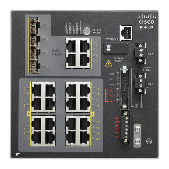
The illustrations in this section provide an overview of the variety of components available on the various switch models in this product family. Not all models are illustrated. Figure 1 Cisco IE-4000-8GT8GP4G-E shown SFP module slots (uplink ports) Power connector DC-B... - Page 7 In all cases, the attached device must be within 328 feet (100 meters). 100BASE-TX traffic requires Category 5 cable. 10BASE-T traffic can use Category 3 or Category 4 cables. When connecting the switch to workstations, servers, routers, and Cisco IP phones, make sure that the cable is a straight-through cable.
-
Page 8: Management Ports
The USB-mini console interface speeds are the same as the RJ-45 console interface speeds. To use the USB-mini console port, you must install the Cisco Windows USB device driver on the device that is connected to the USB-mini console port and that is running Microsoft Windows. -
Page 9: Alarm Connector
Product Overview Alarm Connector Alarm Connector You connect the alarm signals to the switch through the alarm connector. The switch supports two alarm inputs and one alarm output relay. The alarm connector is on the bottom right of the front panel. See Figure 3 on page The alarm connector provides six alarm wire connections. - Page 10 Product Overview LEDs Table 1 Supported SFP Modules 1 Gb SFP (for DL & UL) Distance Mode GLC-SX-MM/ GLC-SX-MMD 220-550 m SFP-GE-S 220-550 m GLC-SX-MM-RGD 220-550 m GLC-LH-SM/ GLC-LH-SMD 550m/10km MMF/SMF SFP-GE-L 550m/10km MMF/SMF GLC-LX-SM-RGD 550m/10km MMF/SMF GLC-T 100 m CAT5 GLC-BX-U 10km...
- Page 11 Product Overview LEDs Figure 4 LEDs on the Cisco IE 4000 Switch Dual Media port LEDs USB mini-Type B (console) port LED SFP module slot LEDs Display Mode Switch 10/100/1000 BASE-T downlink port LEDs HSR/PRP Alarm LEDs SYNCE LED Power connector DC-A LED...
-
Page 12: System Led
Product Overview LEDs Express Setup LED The Express Setup LED displays the express setup mode for the initial configuration. Color Setup Status Off (dark) Switch is configured as a managed switch. Solid green Switch is operating normally. Blinking green Switch is in initial setup, in recovery, or initial setup is incomplete. Solid red Switch failed to start initial setup or recovery because there is no available switch port to which to connect the management station. -
Page 13: Power Status Leds
Product Overview LEDs Alarm IN1 and IN2 Color System Status Alarm IN1 or IN2 not configured. Green Alarm IN1 or IN2 configured, no alarm detected. Blinking red Major alarm detected. Minor alarm detected. Power Status LEDs The switch can operate with one or two DC power sources. Each DC input has an associated LED that shows the status of the corresponding DC input. -
Page 14: Flash Memory Card
Caution: Noncompliant cabling or powered devices can cause a PoE port fault. Use only standard-compliant cabling to connect Cisco pre-standard IP Phones and wireless access points or IEEE 802.3af-compliant devices. You must remove any cable or device that causes a PoE fault. -
Page 15: Management Options
Cisco Network Assistant Cisco Network Assistant is a PC-based network management GUI application optimized for LANs of small- and medium-sized businesses. Using the GUI, you can configure and manage switch clusters or standalone switches. Cisco Network Assistant is available at no cost and can be downloaded from this URL: http://www.cisco.com/en/US/products/ps5931/tsd_products_support_series_home.html... -
Page 16: Network Configurations
Product Overview Network Configurations The switch CLI is based on Cisco IOS software and is enhanced to support desktop-switching features. You can fully configure and monitor the switch. You can access the CLI either by connecting your management station directly to the switch management port, or a console port, or by using Telnet from a remote management station. -
Page 17: Table Of Contents
Exposure to some chemicals could degrade the sealing properties of materials used in the sealed relay device. Statement 381 Warning: Do not work on the system or connect or disconnect cables during periods of lightning activity. Statement 1001 Cisco Systems, Inc. www.cisco.com... -
Page 18: Preparing For Installation
Switch Installation Preparing for Installation Warning: Before performing any of the following procedures, ensure that power is removed from the DC circuit. Statement 1003 Warning: Read the installation instructions before you connect the system to its power source. Statement 1004 Warning: This unit is intended for installation in restricted access areas. - Page 19 Before installation, observe these general guidelines: Caution: Proper ESD protection is required whenever you handle Cisco equipment. Installation and maintenance personnel should be properly grounded by using ground straps to eliminate the risk of ESD damage to the switch. Do not touch connectors or pins on component boards. Do not touch circuit components inside the switch. When not in use, store the equipment in appropriate static-safe packaging.
-
Page 20: Installing Or Removing The Flash Memory Card (Optional)
Cabling is away from sources of electrical noise, such as radios, power lines, and fluorescent lighting fixtures. Verifying Package Contents If any item is missing or damaged, contact your Cisco representative or reseller for support. Installing or Removing the Flash Memory Card (Optional) The software/firmware is stored on the SD card memory from factory default. -
Page 21: Connecting To A Console Port (Optional)
Switch Installation Connecting to a Console Port (Optional) Figure 6 Installing the Flash Memory Card in the Switch Flash Memory Card Slot Install or remove the card: To install a card, slide it into the slot, and press it in until it clicks in place. The card is keyed so that you cannot insert it the wrong way. -
Page 22: Connecting To Power
Switch Installation Connecting to Power Connecting to Power Tools and Equipment Obtain these necessary tools and equipment: Ratcheting torque flathead screwdriver that exerts up to 18 in-lb (2.03 N-m) of pressure. For the protective ground connector, obtain a single or pair of stu size 6 ring terminals (such as Hollingsworth part number R3456B or equivalent). -
Page 23: Switch
Switch Installation Connecting to Power Table 2 Supported Power Supplies PWR-IE65W- PWR-IE65W- PWR-IE170W- PWR-IE170W- PWR-IE50W- PWR-IE50W- PC-DC PC-AC PC-DC PC-AC AC-IEC Current DC-DC AC-DC DC-DC AC-DC AC-DC AC-DC Input 18-60 110/220 VAC 10.8-60 110/220 VAC 110/220 VAC 110/220VAC VDC/4.3 Amp and 88-300 VDC/23 Amp and 88-300... -
Page 24: Switch
Switch Installation Connecting to Power Single ring terminal Two single ring terminals To ground the switch to earth ground by using the ground screw, follow these steps: Use a standard Phillips screwdriver or a ratcheting torque screwdriver with a Phillips head to remove the ground screw from the front panel of the switch. -
Page 25: Switch
Switch Installation Connecting to Power Figure 8 Ground-Lug Screw Ground-Lug Screw Attach the other end of the ground wire to a grounded bare metal surface, such as a ground bus, a grounded DIN rail, or a grounded bare rack. Connecting the Power Converter to an AC Power Source These sections describe the steps required to connect the power converter to an AC power source: ... -
Page 26: Switch
Switch Installation Connecting to Power Connecting the AC Power Source to the Power Converter Caution: AC power sources must be dedicated AC branch circuits. Each branch circuit must be protected by a dedicated two-pole circuit breaker. Caution: Do not turn on AC power until the wiring is secured. Remove the plastic cover from the input power terminals and set it aside. - Page 27 Switch Installation Connecting to Power Warning: An exposed wire lead from a DC-input power source can conduct harmful levels of electricity. Be sure that no exposed portion of the DC-input power source wire extends from the power and relay connector. Statement 122 Insert the twisted-pair wire leads into the terminal block line and neutral connections.
-
Page 28: Switch
Switch Installation Connecting to Power Figure 9 Stripping the Power Connection Wire 0.25 in. (6.3 mm) ± 0.02 in. (0.5 mm) Remove the two captive screws that attach the power connector to the switch, and remove the power connector. Remove both connectors if you are connecting to two power sources. See Figure 10 on page Figure 10 Removing the Power Connectors from the Switch... - Page 29 Switch Installation Connecting to Power Figure 11 Inserting Wires in the Power Connector Power source positive connection Power source return connection Use a ratcheting torque flathead screwdriver to torque the power connector captive screws (above the installed wire leads) to 5in-lb (0.565 Nm). See Figure 12 on page Caution: Do not over-torque the power connector’s captive screws.
-
Page 30: Switch
Switch Installation Connecting to Power Figure 12 Torquing the Power Connector Captive Screws Power connector captive screws Connect the other end of the positive wire to the positive terminal on the DC power source, and connect the other end of the return wire to the return terminal on the DC power source. When you are testing the switch, one power connection is sufficient. -
Page 31: Switch
Switch Installation Connecting to Power Figure 13 Completed DC Power Connections on the Power Connectors Power source A positive connection Power source B positive connection Power source A return connection Power source B return connection If your power source is –48 VDC, this table describes the your wiring connections for Figure 13 on page Power source A ground connection Power source B ground connection... -
Page 32: Switch
Boot fast failures are usually fatal. Call Cisco TAC immediately if your switch does not complete boot fast successfully. Note: You can disable the boot fast and run POST by using the Cisco IOS CLI. See the Cisco IE 4000 Switch Software Configuration Guide for more information. Disconnecting Power To disconnect power after successfully running boot fast, follow these steps: Turn off power to the switch. -
Page 33: Installing The Switch
Switch Installation Installing the Switch Installing the Switch This section describes how to install the switch: Installing the Switch on a DIN Rail, page 29 Removing the Switch from a DIN Rail, page 30 Warning: This equipment is supplied as “open type” equipment. It must be mounted within an enclosure that is suitably designed for those specific environmental conditions that will be present and appropriately designed to prevent personal injury resulting from accessibility to live parts. -
Page 34: Switch
Switch Installation Installing the Switch Figure 14 Position the Hooks Over the DIN Rail DIN Rail Switch Push the switch toward the DIN rail to cause the spring-loaded latch at the bottom rear of the switch to move down, and snap into place. After the switch is mounted on the DIN rail, connect the power and alarm wires, as described in Connecting Alarm Circuits, page... -
Page 35: Connecting Alarm Circuits
Switch Installation Connecting Alarm Circuits Figure 15 Releasing the Spring-Loaded Latch from the DIN Rail Push latch down Remove the switch from the DIN rail. Connecting Alarm Circuits After the switch is installed, you are ready to connect the DC power and alarm connections. ... -
Page 36: Switch
Switch Installation Connecting Alarm Circuits Alarm signals are connected to the switch through the six-pin alarm connector. Three connections are dedicated to the two alarm input circuits: alarm input 1, alarm input 2, and a reference ground. An alarm input and the reference ground wiring connection are required to complete a single alarm input circuit. -
Page 37: Switch
Switch Installation Connecting Alarm Circuits Figure 16 Alarm Connector Alarm Connector Measure two strands of twisted-pair wire (16-to-18 AWG) long enough to connect to the external alarm device. Choose between setting up an external alarm input or output circuit. Use a wire stripper to remove the casing from both ends of each wire to 0.25 inch (6.3 mm) ± 0.02 inch (0.5 mm). Do not strip more than 0.27 inch (6.8 mm) of insulation from the wires. - Page 38 Switch Installation Connecting Alarm Circuits Figure 17 Inserting Wires into the Alarm Connector (Alarm Input Circuit) IN1 - External device connection 1 REF - External device connection 2 Use a ratcheting torque flathead screwdriver to tighten the alarm connector captive screw (above the installed wire leads) to 2 in-lb (0.23 N-m).
-
Page 39: Connecting Destination Ports
Switch Installation Connecting Destination Ports Figure 19 Completed Connections for Three External Alarm Devices on the Alarm Connector IN1 wired connection COM wired connection REF wired connection NO wired connection Attaching the Alarm Connector to the Switch Warning: Failure to securely tighten the captive screws can result in an electrical arc if the connector is accidentally removed. -
Page 40: Switch
RJ-45 connector on the front panel. When connecting to 1000BASE-T-compatible devices, use a twisted four-pair, Category 5 or higher cable. The auto-MDIX feature is enabled by default. For configuration information for this feature, see the Cisco IE 4000 Switch Software Configuration Guide . -
Page 41: Switch
Switch Installation Connecting Destination Ports For detailed instructions on installing, removing, and cabling the SFP module, see your SFP module documentation. Warning: Do not insert and remove SFP modules while power is on; an electrical arc can occur. This could cause an explosion in hazardous location installations. -
Page 42: Switch
Switch Installation Connecting Destination Ports Insert a dust plug into the optical ports of the SFP module to keep the optical interfaces clean. Unlock and remove the SFP module. If the module has a bale-clasp latch, pull the bale out and down to eject the module. If the bale-clasp latch is obstructed and you cannot use your index finger to open it, use a small, flat-blade screwdriver or other long, narrow instrument to open the bale-clasp latch. -
Page 43: Verifying Switch Operation
You can change this setting and configure the port to recognize only an RJ-45 connector or only an SFP module by using the media type interface configuration command. For more information, see the Cisco IE 4000 Switch Command Reference. -
Page 44: Where To Go Next
Switch Installation Where to Go Next... -
Page 45: Switch
Ensure the computer connected to switch is configured with DHCP. Web Browser: disable pop-up blockers and proxy settings. Connect power to the switch. See the wiring instructions in Grounding the Switch, page 19 Wiring the DC Power Source, page Cisco Systems, Inc. www.cisco.com... -
Page 46: Switch
Connect computer to port Gig1/1. LED continues to blink. After computer has IP Address (169.254.0.2), point browser to http://169.254.0.1. Leave the username blank and enter the default password, cisco. Note The switch ignores text in the username field. The Express Setup window appears. - Page 47 If you changed the static IP address on your computer in Step 1, change it to the previously configured static IP address. You can now manage the switch by using the Cisco Network Assistant, Device Manager, or both. See Management Options, page 11 for information about configuring and managing the switch.
- Page 48 Running Express Setup Troubleshooting: If the Device Manager page does not appear: — Confirm that the port LED for the switch port connected to your network is green. — Confirm that the computer that you are using to access the switch has network connectivity by connecting it to a well known web server in your network.
-
Page 49: Accessing The Cli Through The Console Port
For installation procedures, see Switch Installation, page 13 Accessing the CLI Through the Console Port You can enter Cisco IOS commands and parameters through the CLI. Use one of these options to access the CLI: RJ-45 Console Port, page 46 ... - Page 50 Configuring the Switch with the CLI-Based Setup Program Accessing the CLI Through the Console Port Figure 21 USB Mini-Type B Console Port Cover USB Mini-Type B Console Port Cover RJ-45 Console Port Connect the RJ-45-to-DB-9 adapter cable to the 9-pin serial port on the PC. Connect the other end of the cable to the switch console port.
- Page 51 If you are connecting the switch USB-mini console port to a Windows-based PC for the first time, install a USB driver. Installing the Cisco Microsoft Windows XP, 2000, Vista, 7, 8, and 10 USB Device Driver, page 48 for more information.
- Page 52 Click the Hardware tab and choose Device Manager. Expand the Ports section. The assigned COM port appears in parenthesis at the end of the line with this entry: Cisco USB System Management Console. Start the terminal-emulation program on the PC or the terminal. The program, frequently a PC application such as HyperTerminal or ProcommPlus, makes communication possible between the switch and your PC or terminal.
-
Page 53: Entering The Initial Configuration Information
You must assign an IP address and other configuration information necessary for the switch to communicate with the local routers and the Internet. This information is also required if you plan to use Device Manager or Cisco Network Assistant to configure and manage the switch. -
Page 54: Completing The Setup Program
Enter virtual terminal password: terminal-password (Optional) Configure Simple Network Management Protocol (SNMP) by responding to the prompts. You can also configure SNMP later through the CLI, Device Manager, or the Cisco Network Assistant application. To configure SNMP later, enter no. - Page 55 If you enter N, the switch appears as a candidate switch in the Cisco Network Assistant GUI. You can configure the switch as a command switch later through the CLI, Device Manager, or the Cisco Network Assistant application. To configure it later, enter no.
- Page 56 To use the CLI, enter commands at the Switch> prompt through the console port by using a terminal emulation program or through the network by using Telnet. For configuration information, see the switch Cisco IE 4000 Switch Software Configuration Guide.
-
Page 57: Troubleshooting
Boot fast failures are usually fatal. Contact your Cisco TAC representative if your switch does not successfully complete boot fast. Note: You can disable the boot fast and run POST by using the Cisco IOS CLI, see the Cisco IE 4000 Switch Software Configuration Guide for more information. Switch LEDs Look at the port LEDs information when troubleshooting the switch. -
Page 58: Link Status
Verify the cable type. See Cable and Connectors, page SFP Module Use only Cisco SFP modules. Each Cisco module has an internal serial EEPROM that is encoded with security information. This encoding verifies that the module meets the requirements for the switch. ... -
Page 59: Interface Settings
You can enable UniDirectional Link Detection (UDLD) on the switch to help identify unidirectional link problems. For information about enabling UDLD on the switch, see the “Understanding UDLD” section in the switch software configuration guide on Cisco.com. Switch Performance Speed, Duplex, and Autonegotiation Port statistics that show a large amount of alignment errors, frame check sequence (FCS), or late-collisions errors, might mean a speed or duplex mismatch. -
Page 60: Cabling Distance
Finding the Switch Serial Number If you contact Cisco Technical Assistance, you need to know the serial number of your switch. The serial number is on the compliance label on the right-hand side of the switch. See Figure 23 on page 57. - Page 61 Troubleshooting Finding the Switch Serial Number Figure 23 Serial Number Location for the Cisco IE 4000 Switches Compliance Label...
- Page 62 Troubleshooting Finding the Switch Serial Number...
-
Page 63: Technical Specifications
1. lfm = linear feet per minute. Note: The safety certifications apply only to ambient temperatures under 158°F (70°C). However, the Cisco IE 4000 switch can function in the substation and traffic signal installations under the environmental conditions shown in Table 3 on page Cisco Systems, Inc. - Page 64 Technical Specifications Technical Specifications Technical Specifications The technical specifications for the Cisco IE 4000 switches are as follows: Table 4 Cisco IE 4000 Technical Specifications Environmental Ranges Storage temperature –40 to 185°F (–40 to 85°C) Operating temperature -40C to +74C ...
- Page 65 PWR-IE65W-PC-DC=: 2.6 (1.18 Kg) PWR-IE65W-PC-AC=: 2.7 (1.24 Kg) Dimensions All IE 4000 models have the following dimensions: 6.12 x 6.12 x 5.09 in. (H x W x D) (155.4 x 155.4 x 129.2 mm) Including DIN Rail ...
-
Page 66: Alarm Ratings
Technical Specifications Alarm Ratings 4. To calculate the depth excluding the rail, subtract 0.22 in. (0.6 cm). Alarm Ratings The alarm ratings for the Cisco IE 4000 switches are below. Table 5 Cisco IE 4000 Alarm Ratings Alarm Ratings Specification Alarm input electrical specification No power required—open or closed state detected. -
Page 67: Connector Specifications
Label 4 5 6 7 8 Note: For the three models of IE 4000 switch that support PoE, connector pins 4 and 5 supply +48 VDC and pins 7 and 8 are the DC voltage return lines. SFP Module Connectors... -
Page 68: Console Port
Cable and Connectors Connector Specifications Figure 25 Fiber-Optic SFP Module LC Connector Warning: Invisible laser radiation may be emitted from disconnected fibers or connectors. Do not stare into beams or view directly with optical instruments. Statement 1051 Dual-Purpose Ports The 10/100/1000 Ethernet ports on the dual-purpose ports use RJ-45 connectors. Figure 2610/100/1000 Port Pinouts, page 64 shows the pinouts. -
Page 69: Alarm Port
Cable and Connectors Cables and Adapters Figure 28 USB Type A-to-USB 5-Pin Mini-Type B Cable The RJ-45 console port uses an 8-pin RJ-45 connector The supplied RJ-45-to-DB-9 adapter cable is used to connect the console port of the switch to a console PC. You need to provide a RJ-45-to-DB-25 female DTE adapter if you want to connect the switch console port to a terminal. - Page 70 Cable and Connectors Cables and Adapters A mode-field diameter/cladding diameter = 9 micrometers/125 micrometers. A mode-conditioning patch cord is required when using 1000BASE-LX/LH SFP modules, MMF, and a short link distance . Using an ordinary patch cord can cause transceiver saturation, resulting in an elevated bit error rate (BER). When using the LX/LH SFP module with 62.5-micron diameter MMF, you must also install a mode-conditioning patch cord between the SFP module and the MMF cable on both the sending and receiving ends of the link.
- Page 71 Cable and Connectors Cables and Adapters Table 6 Commercial SFPs—Fiber-Optic SFP Module Port Cabling Specifications (continued) Type of SFP Module Model Wavelength Fiber Core Modal Cable Distance (nanometers) Type Size/Claddin Bandwidth g Size (MHz/km) (micron) 100BASE-ZX GLC-FE-100ZX 1550 G.652 — 49.7 miles (80 km) 100BASE-ZX GLC-LH-SMD...
-
Page 72: Cable Pinouts
Cable and Connectors Cables and Adapters Table 8 Extended Temperature SFPs—Fiber-Optic SFP Module Port Cabling Specifications Type of SFP Model Wavelength Fiber Core Modal Cable Distance Module (nanometers) Type Size/Claddi Bandwidth ng Size (MHz/km) (micron) 100BASE-BX10-U GLC-FE-100BX 1310 TX G.652 —... - Page 73 Cable and Connectors Cables and Adapters Figure 31 Four Twisted-Pair Straight-Through Cable Schematic for 1000BASE-T Ports Switch Router or PC 1 TP0+ 1 TP0+ 2 TP0- 2 TP0- 3 TP1+ 3 TP1+ 6 TP1- 6 TP1- 4 TP2+ 4 TP2+ 5 TP2- 5 TP2- 7 TP3+...
-
Page 74: Console Port Adapter Pinouts
Console Port (DTE) Terminal Adapter Device Signal DB-9 Pin Signal Note: The RJ-45-to-DB-25 female DTE adapter is not supplied with the switch. You can order this adapter from Cisco (part number ACS-DSBUASYN=). Switch RJ-45-to-DB-25 Console Console Adapter Device Port (DTE) - Page 75 Hazardous Location Installation Information This appendix provides hazardous location installation information for the Cisco IE 4000 switches. Hazardous Area Installation Warnings Warning: Exposure to some chemicals could degrade the sealing properties of materials used in the sealed relay device. Statement 381...
-
Page 76: Emc Environmental Conditions For Products Installed In The European Union
Hazardous Location Installation Information Hazardous Area Installation Warnings Warning: Explosion Hazard—Do not connect or disconnect wiring while the field-side power is on; an electrical arc can occur. This could cause an explosion in hazardous location installations. Be sure that power is removed or that the area is nonhazardous before proceeding. - Page 77 Hazardous Location Installation Information Hazardous Locations Standards Hazardous Locations Standards Hazardous location standards for the Cisco IE 4000 switches: Environmental Ranges Operating temperature –29 to 165°F (–34 to 74°C) Storage temperature –40 to 185°F (–40 to 85°C) Operating altitude Up to 13,000 ft (3962 m)
- Page 78 Hazardous Location Installation Information Hazardous Locations Standards...