Table of Contents
Advertisement
GE Consumer & Industrial
Multilin
LM10 revision: 1.7x
GE publication code: GEK-106642E
GE Multilin part number: 1601-0165-A6
Copyright © 2008 GE Multilin
GE Multilin
215 Anderson Avenue, Markham, Ontario
Canada L6E 1B3
Tel: (905) 294-6222 Fax: (905) 201-2098
Internet:
http://www.GEmultilin.com
*1601-0165-A6*
LM10 MOTOR PROTECTION SYSTEM – INSTRUCTION MANUAL
LM10 Motor Protection System
Instruction Manual
I I SO9001:2000
GE Multilin's Quality
Management System is
registered to ISO9001:2000
QMI # 005094
UL # A3775
1–1
Advertisement
Table of Contents

Related Manuals for GE LM10


Summary of Contents for GE LM10
- Page 1 215 Anderson Avenue, Markham, Ontario I I SO9001:2000 Canada L6E 1B3 Tel: (905) 294-6222 Fax: (905) 201-2098 Internet: http://www.GEmultilin.com GE Multilin's Quality Management System is registered to ISO9001:2000 QMI # 005094 *1601-0165-A6* UL # A3775 LM10 MOTOR PROTECTION SYSTEM – INSTRUCTION MANUAL 1–1...
- Page 2 The contents of this manual are the property of GE Multilin Inc. This documentation is furnished on license and may not be reproduced in whole or in part without the permission of GE Multilin. The content of this manual is for informational use only and is subject to change without notice.
-
Page 3: Table Of Contents
..........................3-19 EYPAD PDU SCREENS AND MENUS ....................3-21 ..................... 3-21 TARTUP CREEN ................ 3-21 ISTORY ECORD AND TATUS CREENS ..................... 3-21 ONFIGURATION ENERVISTA LM10 SOFTWARE ..................3-23 ........................3-23 ESCRIPTION ......................3-23 UNCTIONAL ETAILS LM10 MOTOR PROTECTION SYSTEM – INSTRUCTION MANUAL 1–I... - Page 4 APPENDIX DEVICENET OVERVIEW ....................A-1 ........................A-1 ESCRIPTION (CAN) ................A-2 ONTROLLER ETWORK ....................A-2 EVICE PERATIONS (I/O) M ........A-3 XPLICIT ESSAGING AND NPUT UTPUT ESSAGING ............A-3 DEFINED ASTER LAVE ONNECTION 1–II LM10 MOTOR PROTECTION SYSTEM – INSTRUCTION MANUAL...
- Page 5 EVICE EATURES ..............A-3 AXIMUM ABLE ENGTHS FOR EVICE ................. A-4 EVICE PECIFICATION IGHLIGHTS LM10 AND GE FANUC 90-30 WITH DEVICENET™ .............A-6 ..........................A-6 VERVIEW GE F 90-30 PLC H ................A-6 ANUC ARDWARE ....................A-6 ETWORK ONFIGURATION ................... A-6...
- Page 6 TABLE OF CONTENTS 1–IV LM10 MOTOR PROTECTION SYSTEM – INSTRUCTION MANUAL...
-
Page 7: The Lm10 Relay
1.1.1 The LM10 Relay The GE Multilin LM10 Motor Protection System is a modular device designed to protect motors from various fault conditions. This device interfaces with a DeviceNet network. The network will monitor and control the relay status and functions. The relay also has the capability of operating in a standalone mode. -
Page 8: Overview
The two control relays are labeled “RUN 1” and “RUN 2”. These relays are enabled on command from the control logic. If the LM10 detects a fault condition the relays will be de- energize, causing the motors to shut down. -
Page 9: Power Supply
1.2.4 Power Supply The LM10 Motor Protection System has an on-board power supply with a fuse that converts the AC input to the levels necessary to operate this device. The operating range is 96 to 140 V AC, nominal 120 V control power (80% to 117%). The supply has programmable auto-restart capability of up to 4 seconds. -
Page 10: Features
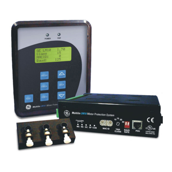
The main task of the programming and display unit (PDU) is to provide status information to a local user. The PDU can display the requested parameter(s) on the LCD in either English or Spanish. Additionally, the PDU can be used to configure the LM10 via the RS232 serial communications port. - Page 11 The conditions at the PDU without hardware to time of fault are displayed and facilitate door mounting. can be scrolled through using the UP/DOWN arrow keys. 849713A3.CDR FIGURE 1–2: LM10 Features LM10 MOTOR PROTECTION SYSTEM – INSTRUCTION MANUAL 1–5...
-
Page 12: Ordering
ORDERING CHAPTER 1: INTRODUCTION Ordering 1.4.1 Order Codes The order codes for the LM10 Motor Protection System are shown below. Table 1–1: LM10 Order Codes LM10 – D* – CT** – GF** – – Base unit LM10 LM10 Motor Protection System... -
Page 13: Specifications
Overvoltage pickup level: 117% of nominal voltage (140 V) Pickup accuracy: ..........±5% Trip time:.............0.5 second Timing accuracy:..........±200 ms 1.5.2 Metering PHASE CURRENT Resolution: ............0.1 A Range:..............0.05 to 8 × CT Primary (3200.0 A max.) Accuracy: ............±5% of full scale LM10 MOTOR PROTECTION SYSTEM – INSTRUCTION MANUAL 1–7... -
Page 14: Control Functions
CT sensor pack: ..........NEMA starter size 1 to 6 (27 A, 90 A primary) Sensor Input:.............0 to 0.27 V AC Phase CT input:..........0 to 5 A Phase CT primary: ..........75, 100, 120, 150, 200, 225, 250, 300, 400, 500, 600, 700, 1–8 LM10 MOTOR PROTECTION SYSTEM – INSTRUCTION MANUAL... - Page 15 Recommended Supply voltage: ....100 to 135 V AC When the LM10 contact inputs are connected to the remote devices for the input signal via long cables, induced voltages may be present at the input terminal of LM10 relay. The contact input status could be detected as closed if the induced voltages are greater than 33V.
-
Page 16: Ct Dimensions
20 amp, 1x 4.62" window 1.5.6 Outputs RELAY OUTPUTS Relay pilot duty:..........5 A at 120 V AC 5 A at 28 V DC 1.5.7 Communications DEVICENET Functionality:............group 2 slave only Device type:............motor starter 1–10 LM10 MOTOR PROTECTION SYSTEM – INSTRUCTION MANUAL... -
Page 17: Environmental
Mac id: ..............0 to 63 via DIP switches Supports: ............Poll, COS and Cyclic IO, and explicit messaging LEDs:..............network status and device status SERIAL COMMUNICATIONS Serial port: ............RJ11 4-pin connector for Enervista LM10 Setup software or to PDU PANEL DISPLAY UNIT (OPTIONAL) Display:..............16 character × 4 line display 1.5.8... - Page 18 SPECIFICATIONS CHAPTER 1: INTRODUCTION 1–12 LM10 MOTOR PROTECTION SYSTEM – INSTRUCTION MANUAL...
-
Page 19: Devicenet
2.1.1 DeviceNet The LM10 has one micro-style (Brad Harrison style) connector that allows the purchase of pre-built cables for attachment to the unit and the ability to daisy chain from one unit to the next. These connectors meet all DeviceNet physical layer requirements. -
Page 20: Control Terminals
Description +5 V (PDU use only) The LM10 base unit and PDU are designed to use a maximum 36-inch cable when the PDU is mounted door-mounted alone. A shorter cable can be used when the two units are door- mounted together. -
Page 21: Sensor Pack Input
CT phase C common 2.1.5 Wiring Diagram A typical LM10 wiring diagram is shown below. The relay should be programmed as “Maintained Off” (under “Other Settings”) for momentary start input. See page 4–34 for additional details. LM10 MOTOR PROTECTION SYSTEM – INSTRUCTION MANUAL... - Page 22 WIRING CHAPTER 2: INSTALLATION FIGURE 2–4: LM10 Wiring Diagram 2–16 LM10 MOTOR PROTECTION SYSTEM – INSTRUCTION MANUAL...
-
Page 23: Mounting
Front door mounting feature (see PDU Door Mount on page 2–18). MCC hint: Grasp the bottom of the LM10 in one hand, and slide in opposite directions to detach. Attach the mounting plate to the bracket provided using four (4) screws (not included). -
Page 24: Pdu Door Mount
The PDU can be door-mounted using the gasket and six screws provided. The rear of the unit protrudes through a cutout and is accessible from inside the door. Recommended cutout dimensions and screw hole locations are shown below. FIGURE 2–7: PDU Door-mount Dimensions 2–18 LM10 MOTOR PROTECTION SYSTEM – INSTRUCTION MANUAL... -
Page 25: Liquid Crystal Display
History: Pressing the History button displays the last ten (10) fault history records. Each history record contains a snapshot of conditions when the unit last faulted. The following items are displayed: fault type, phase currents, ground current, voltage, LM10 MOTOR PROTECTION SYSTEM – INSTRUCTION MANUAL 3–19... - Page 26 • Status: Pressing the Status button displays the current conditions of the LM10. The following items are displayed: phase currents, ground current, voltage, kW, power factor, average current, current unbalance, and elapsed motor hours.
-
Page 27: Pdu Screens And Menus
The main startup screen displays the following information. These parameters are not programmable via serial communications, but rather are displayed for convenience. See Switches on page 1–4 for setting instructions. • PDU software version displayed briefly, then replaced by the LM10 software version • Trip class •... - Page 28 Restore Factory Configuration Screen: This screen, available only to Configurator or higher login, resets all parameters to factory defaults. The PDU will prompt the user to confirm the request prior to resetting parameters. Default settings are listed in Table 3 Configuration Parameters. 3–22 LM10 MOTOR PROTECTION SYSTEM – INSTRUCTION MANUAL...
-
Page 29: Enervista Lm10 Software
3.3.1 Description The EnerVista LM10 software is intended as an interface to the GE Multilin LM10 Motor Protection System. It has all the capabilities of the GE Multilin LM10 Motor Protection System, although some of the operations may differ slightly. The major difference is configuration parameters are not directly changed from the PDU screen, they must be downloaded after modifying. - Page 30 Manual: Opens the enerVista LM10 setup software help file. • About: Displays the enerVista LM10 setup software version and information. The EnerVista LM10 software uses hot keys for the following that equate to a mouse click on the PDU keys. Table 3–1: EnerVista Hot Keys...
-
Page 31: Descriptions
(see Switches on page 1–4 for details on setting the trip class). The LM10 monitors average current of the three phases over time to determine the motor condition. LM10 MOTOR PROTECTION SYSTEM – INSTRUCTION MANUAL... - Page 32 OVERCURRENT FAULT CONDITIONS CHAPTER 4: FUNCTIONALITY FIGURE 4–1: Cold Motor Trip Curves FIGURE 4–2: Hot Motor Trip Curves 4–26 LM10 MOTOR PROTECTION SYSTEM – INSTRUCTION MANUAL...
-
Page 33: Trip Curves Example
FIGURE 4–3: Trip Curve with Jam and Stall Enabled The LM10 will trip on a jam or stall condition if these faults are enabled (see Run 1 and Run 2 Setup on page 4–32). The overcurrent curve cannot be disabled. Therefore, if the jam or stall values are set greater than the time allowed by the standard trip curve, the LM10 will trip before a jam or stall condition can be reached. - Page 34 99. When the number counts down to 0, the message “Ready to Run” will be displayed to indicate the RESET button may be pressed. Once the LM10 is successfully reset, the user may activate the run command. 4–28...
-
Page 35: Configuration Settings
CHAPTER 4: FUNCTIONALITY CONFIGURATION SETTINGS Configuration Settings 4.2.1 Overview An overview of the LM10 programmable parameters is shown below. Table 4–1: LM10 Programmable Parameters Parameter Range/Options Default Reference Control power transformer 200:120, 240:120, 480:120, 600:120, 240:120 page 4–31 CPT ratio... -
Page 36: Main Menu
Configuration Time Delays See page –34. Other Settings Aux Rly Faults Configuration Other Settings See page –34. Aux Rly Faults Passcode, Login Configuration Aux Rly Faults See page –36. Passcode,login Run Operations 4–30 LM10 MOTOR PROTECTION SYSTEM – INSTRUCTION MANUAL... -
Page 37: Language
(current transformer): Select a CT ratio from the choices provided. The first two menu choices refer to sensor packs, while the remaining options are ratios of compatible CTs that might be used with the LM10. • Turns: The CT may be configured so that wires are passed through the CT multiple times to increase values. -
Page 38: Starter Type
• “Custom” Any of the first five allows the LM10 to automatically populate required fields (FLA, etc.) for Run 2 based on Run 1 data. These fields are automatically populated, even for full voltage non-reversing motors, and do not require a separate configuration step. Even if logged... - Page 39 Enter the full load current (FLA) of the motor. The LM10 will not accept full load currents that exceed the CT or sensor pack rating; however, lower values are acceptable. For best results, enter the proper FLA for the motor being used.
-
Page 40: Time Delays
AuxSns1 AuxSns2 (auxiliary sense failure): Should the LM10 detect that a contactor did not open/close according to its command, an auxiliary sense (AuxSns) trip failure will be recorded in the fault record and shut down the run relay. This fault is factory preset at 0.4 seconds. - Page 41 No seal in contact is required. In the maintained mode a run switch must stay closed if opened the LM10 will stop the motor. The stop switch input for safety reasons will interrupt the run relay in maintained or momentary mode. If the run switch is on when the stop command is given, it will need to be turned off and back on to get the motor running again.
-
Page 42: Auxiliary Relay Faults
Poll group 4 option (7 bytes) is available only for firmware rev 1.70 and higher. If PDU v1.70 or higher is used for LM10 firmware v1.6x and lower, Poll Data group 4 (which is unavailable in firmware v1.6x and lower) will be displayed in the PDU but cannot be set to the MPR unit. -
Page 43: 4.2.10 Passcode And Login
As an extra security feature, the login level can automatically be set to "User" via DeviceNet communications. Refer to Assembly Object, Class Code 4, Instance 100 for more information. LM10 MOTOR PROTECTION SYSTEM – INSTRUCTION MANUAL 4–37... -
Page 44: 4.2.11 Run Operations
With DeviceNet fault enabled and scanner connections not yet established, switching to DeviceNet will cause the DeviceNet fault and stop any run condition of the LM10. Hard- wired Stop will always have priority. If stop terminal 3 is powered, the LM10 will not run. 4.2.12 Factory Default... -
Page 45: Status Values
0.0 to 6553.5 kW Status Active Range: 0.0 to 3200.0 A Avg Cur: Status Active Range: 0 to 250% %CurUnBl: Status Active Range: 0 to 65535 hours in steps of 1 Motor Hrs: LM10 MOTOR PROTECTION SYSTEM – INSTRUCTION MANUAL 4–39... - Page 46 • Motor Hrs: The LM10 keeps a running tally of motor operation time, incremented hourly up to 65535 hours. Upon power loss, the unit will retain any whole number of hours already recorded. This feature is a great service tool. An example is for bearing change;...
-
Page 47: History Values
History Values 4.4.1 Last Trip Data Data for the last ten trips is stored in the LM10. Press the HISTORY key to access these values. Pressing the HISTORY key multiple times scrolls between trips 1 to 10. GE LM10 1.70... -
Page 48: Motor Start/Stop Logic
CHAPTER 4: FUNCTIONALITY Motor Start/Stop Logic LM10 is designed to run in RUN1 and RUN2 mode. However, to illustrate this, only RUN1 mode is described below. The block logic diagram for RUN1 operation is shown in fig. 4-5. Motor Status: Running 1... - Page 49 * Devicenet Commands can be issued onl y if the Devicenet control switch input is asserted ** The Maintained switch s etting should be set to ON FIGURE 4–5: Motor RUN1 Start/Stop Logic LM10 MOTOR PROTECTION SYSTEM – INSTRUCTION MANUAL 4–43...
- Page 50 MOTOR START/STOP LOGIC CHAPTER 4: FUNCTIONALITY 4–44 LM10 MOTOR PROTECTION SYSTEM – INSTRUCTION MANUAL...
-
Page 51: Description
Data Group The LM10 supports Polling, COS, and Cyclic IO data operations, and is certified as ODVA DeviceNet CONFORMANCE TESTED™." The COS/CYC operation returns one byte of device status described under the Assembly object, class 4, instance 54. Refer to the following section for polling data. - Page 52 2 (Hi), 3 (Lo) Phase A current UINT 1 word 4 (Hi), 5 (Lo) Phase B current UINT × 0.1 A 1 word 6 (Hi), 7 (Lo) Phase C current UINT × 0.1 A 5–46 LM10 MOTOR PROTECTION SYSTEM – INSTRUCTION MANUAL...
-
Page 53: Identity Object
Get_Attribute_Single: Returns the contents of the given attribute. 0x4B Allocate: Creates predefined M/S connections. 0x4C Release: Deletes predefined M/S connections. DeviceNet Object, Class Code 3, Attributes: Attribute Access Name/Description Data Type Value Revision UINT LM10 MOTOR PROTECTION SYSTEM – INSTRUCTION MANUAL 5–47... -
Page 54: Assembly Object
Extended device outputs (see format and byte see below mapping below) Data Formats for Extended Device Outputs Bit Position Name Value Bit 7 Reserved Bit 6 Reserved Bit 5 Reserved Bit 4 Reserved 5–48 LM10 MOTOR PROTECTION SYSTEM – INSTRUCTION MANUAL... - Page 55 Name/Description Data Type Value Device inputs (see format/mapping below) byte see below Data Formats for Device Inputs Bit Position Name Value Bit 7 Reserved Bit 6 Reserved Bit 5 Control from Net LM10 MOTOR PROTECTION SYSTEM – INSTRUCTION MANUAL 5–49...
- Page 56 Run 1 * If the LM10 has been put into Admin mode via the PDU display and this bit is set to '1', the PDU display will continue to appear to be in Config mode but no settings will be able to be changed.
- Page 57 1 word Current unbalance UINT 1 word Power UINT × 0.1 kW Assembly Object, Class Code 4, Instance 104 Attribute Access Name/Description Data Type Value Poll Data Group 3 see below see below LM10 MOTOR PROTECTION SYSTEM – INSTRUCTION MANUAL 5–51...
-
Page 58: Connection Object
Name/Description Data Value none Connection Object, Class Code 5, Instance 1 (explicit message connection): Attribute Access Name/Description Data Type Value State BYTE 0x03 Instance_type BYTE 0x00, 0x01 Export class trigger BYTE 0x83 5–52 LM10 MOTOR PROTECTION SYSTEM – INSTRUCTION MANUAL... - Page 59 Value State BYTE 0x03 Instance_type BYTE 0x01 Export class trigger BYTE 0x00, 0x02, 0x10, 0x12 Produced connection ID UINT MAC ID Consumed connection ID UINT MAC ID Initial comm. characteristics UINT 0x01 LM10 MOTOR PROTECTION SYSTEM – INSTRUCTION MANUAL 5–53...
-
Page 60: Ack Handler Object
Overload Object, Class Code 0x2C, Services: Code Name and Description of Services Available to this Object 0x0E Get_Attribute_Single: Returns the contents of the given attribute. Overload Object, Class Code 0x2C, Attributes: Attribute Access Name/Description Data Value none 5–54 LM10 MOTOR PROTECTION SYSTEM – INSTRUCTION MANUAL... -
Page 61: 5.1.10 Extension Object
User setting, Run 2 ground fault Trip, Time 0x06 Get/set User setting, Run 1, jam Trip, Time 0x07 Get/set User setting, Run 2, jam Trip, Time 0x08 Get/set User setting, Run 1, stall Trip, Time LM10 MOTOR PROTECTION SYSTEM – INSTRUCTION MANUAL 5–55... - Page 62 *This call function has the same result as pressing the Reset key on the PDU display Applies to revisions 1.50 and higher The data type format codes for class code 0x64, instance 1 are shown below. 5–56 LM10 MOTOR PROTECTION SYSTEM – INSTRUCTION MANUAL...
-
Page 63: 5.1.11 Data Formats
F8: Current Transformer Format: two bytes in format 0xHHLL, where LL is the CT ratio and HH is reserved Byte LL enumeration: Value CT Ratio Value CT Ratio 27 A sensor pack 250:5 LM10 MOTOR PROTECTION SYSTEM – INSTRUCTION MANUAL 5–57... - Page 64 2S1W (two-speed one winding; Run-2, 4:1 ratio of Run-1) 2S2W (two-speed two winding; Run-2, 2:1 ratio of Run-1) Custom F13: CT Turns Format: two bytes in format 0xHHLL, where LL is the number of CT turns and HH is reserved 5–58 LM10 MOTOR PROTECTION SYSTEM – INSTRUCTION MANUAL...
- Page 65 ---- ---- ---1 ---- Stall ---- ---- --1- ---- Current unbalance ---- ---- -1-- ---- Aux sense ---- ---- 1--- ---- Load loss ---- ---1 ---- ---- Reserved ---- --1- ---- ---- DeviceNet stop LM10 MOTOR PROTECTION SYSTEM – INSTRUCTION MANUAL 5–59...
- Page 66 DeviceNet control ---- ---- -1-- ---- DeviceNet active ---- ---- 1--- ---- DeviceNet issued last stop ---1 ---- ---- ---- Reserved --1- ---- ---- ---- Reserved -1-- ---- ---- ---- Login > user 5–60 LM10 MOTOR PROTECTION SYSTEM – INSTRUCTION MANUAL...
-
Page 67: 5.1.12 Special Application
This will disable any hard-wired 120 V AC RUN inputs from being accepted as a command to the LM10. The LM10 can read the state of these inputs through the DeviceNet protocol. - Page 68 Stop. To watch for RUN1 one would test for bit 2 being on. EX: LBY and 0x04 is not equal to 0x00. Do not switch out of DeviceNet Control while the motor is running. In such a case the LM10 will issue a Stop command under the assumption that the network is down.
-
Page 69: Serial Port
The data is in ‘big endian’ format here (big end first: MSB-LSB). The packet is outlined below: Bit Position Name Bit 7 Bit 6 Service Bit 5 Attribute Bit 4 Data 3 Bit 3 Data 2 Bit 2 Data 1 Bit 1 Data 0 Bit 0 Checksum LM10 MOTOR PROTECTION SYSTEM – INSTRUCTION MANUAL 5–63... - Page 70 SERIAL PORT CHAPTER 5: COMMUNICATIONS 5–64 LM10 MOTOR PROTECTION SYSTEM – INSTRUCTION MANUAL...
-
Page 71: Release Dates
Update Manual to A5 and Firmware (and Firmware references) to v1.70 1.3.3 Change revision in the images of the product from 1.60 to 1.0 1.5.2 Change Phase Current range 1.5.2 Change Average Current range LM10 MOTOR PROTECTION SYSTEM – INSTRUCTION MANUAL 6–65... - Page 72 Change bit 5 from "Reserved" to "Security to Min" Add note at the bottom of the table Extension Object, Class Code 0x64, Instance 1 5.1.11 Add a note to "Reset LM10" at attribute 0x2E 5.1.1 - 5.1.5 Miscellaneous text/table changes 6–66...
-
Page 73: Warranty
In the event of a failure covered by warranty, GE Multilin will undertake to repair or replace the device providing the warrantor determined that it is defective and it is returned with all transportation charges prepaid to an authorized service centre or the factory. - Page 74 WARRANTY CHAPTER 6: MISCELLANEOUS 6–68 LM10 MOTOR PROTECTION SYSTEM – INSTRUCTION MANUAL...
-
Page 75: Description
In addition to reading the state of discrete devices, DeviceNet provides the capability of reading analog data such as temperatures, load current or to count the number of items that have passed on a conveyor belt in the given period. LM10 MOTOR PROTECTION SYSTEM – INSTRUCTION MANUAL A–1... -
Page 76: Controller Area Network (Can
Each object has its own parameters called attributes (such as vendor ID). The behavior of a device is governed by these attributes. Once the connection is established, all the data exchanged across this connection are handled by the corresponding connection instance. A–2 LM10 MOTOR PROTECTION SYSTEM – INSTRUCTION MANUAL... -
Page 77: Explicit Messaging And Input/Output (I/O) Messaging
DeviceNet defines the maximum cable lengths (trunk and drop cables) to ensure the propagation of the transmitted message falls within the acceptable limits. The upper boundaries of the trunk cable and drop cable length are shown below. LM10 MOTOR PROTECTION SYSTEM – INSTRUCTION MANUAL A–3... -
Page 78: Devicenet Specification Highlights
Connections: The DeviceNet communication protocol is based on the idea of connections. Connections must be established with a device in order to exchange information with that device. A–4 LM10 MOTOR PROTECTION SYSTEM – INSTRUCTION MANUAL... - Page 79 This makes possible user-friendly configuration tools that can be easily updated without having to constantly revise the configuration software tool. LM10 MOTOR PROTECTION SYSTEM – INSTRUCTION MANUAL A–5...
-
Page 80: Lm10 And Ge Fanuc 90-30 With Devicenet
• DeviceNet Slave Module: GE Multilin LM10 Motor Protection System A.2.3 Network Configuration To connect the LM10 Motor Protection System to the DeviceNet™ master card (IC693DNM200), refer to chapter 2 of the Series 90-30 Programmable Controller manual (publication number GFK-2196). -
Page 81: Polling Input/Output Connection
GE Multilin folder, and drag it onto the DeviceNet™ master card. Set the MAC ID on LM10 module equal to the one displayed under the General tab of the Slave Properties window. To see the slave properties window, right click on the Slave Device, add it to the Master, and select Network Setting. - Page 82 MAC ID 2, then address %I00002 will read “2”. Start the PLC. The NS LED on the LM10 (MAC ID 1) will turn solid green once the connection is established, and address %I00001 will read “1”. Double-click on GE LM10 to view the data areas.
- Page 83 This changes address %I00083 to read “0”, indicating that the Run1 relay is off. When the LM10 goes into a fault condition, address %I00081 will toggle to “1”. To reset the LM10 after recovering from the fault state, toggle address %Q00019. Once the LM10 is in the “Ready to Run”...
-
Page 84: Cos (Change Of State) Input/Output Connection
Basically, the same data is available in both COS and Cyclic connections. The primary difference is in the way the data is reported to the DeviceNet™ master. The Cyclic I/O connection is also used for alarm and status notification. In the LM10 system, cyclic data is described in Object Class 4, Instance 54. -
Page 85: Explicit Messaging
PLC system. The module receives the command and performs the requested function. Monitoring Data: The ladder logic for monitoring data from the GE LM10 Motor Protection System using COMMREQ is shown in Ladder Logic for Data Monitoring on page A–13. The ladder logic is configured as follows: •... - Page 86 Refer to Chapter 5: Communications for a complete description of each word. In the ladder below, the Trip Class is read from the slave (LM10 device) MAC ID 1. Some key word settings to obtain the LM10 Trip Class from Slave 1 are shown below: •...
- Page 87 In the ladder shown. we are logging in, setting the user level, and entering the configuration mode of the LM10 relay set to MAC ID 9. Some key word settings to login to the LM10 from Slave 9 are shown below: •...
- Page 88 Refer to DeviceNet Object Model Class 64, Instance for additional details. In the ladder shown. we are setting the FLA Run1 parameter of the LM10 relay from slave 9 (MAC ID 9). Some key word settings are shown below: •...
- Page 89 FIGURE A–3: Ladder Logic for Setting Changes Login (User Level) to the LM10: The ladder logic for login (user level) to the LM10 using COMMREQ is shown below. Some key word settings to login (user level) to the LM10 from Slave 9 are shown below: •...
- Page 90 CHAPTER A: To view the slave number of slaves connected to master card, add address %I00001 to the new reference table. Now, address %I000010 will read “1”, since the LM10 is connected to the master as slave 1 (MAC ID 1).
-
Page 91: Lm10 And Allen-Bradley Slc500 Via Devicenet
This section describes DeviceNet communications between the Allen-Bradley SLC500 PLC card with the GE Multilin LM10 Motor Protection System. The application example shows how to establish communications between Allen-Bradley SLC500 PLC (1747-SDN DeviceNet Scanner) card with the LM10 via Polled I/O Messaging, COS I/O Messaging, and Explicit Messaging. A.3.2... -
Page 92: Changing The Mode Of Operation
Scanner card, 1770-KFD, and LM10 relay) is complete, click the Online icon and upload the network. Scanning for the Nodes on the Network will start. Using the EDS Wizard, add the LM10 to the hardware list in RSNetworx. A sample screen of RSNetworx with 3 nodes is shown below. -
Page 93: Configuring The Slave Device
Prog (programming). When the scanner is in Idle mode, the 7-segment indicator will flash code “80” and the NS (Network Status) LED indicator on the LM10 changes to flashing green, indicating Online, Not Connected. If the Run1 contactor is switched on via O:1/16, then Run1 will drop/turn off when the scanner changes to Idle mode. -
Page 94: Control And Monitoring Of The Lm10
After adding the input/output parameters, you will be prompted for downloading to node 9 A.3.7 Control and Monitoring of the LM10 Polling I/O messaging is for control and monitoring of LM10 relay parameters. A–20 LM10 MOTOR PROTECTION SYSTEM – INSTRUCTION MANUAL... -
Page 95: Explicit Messaging With The Lm10 Relay
Also, the Status data received will be reflected in Status Word I:s.0 Bit-15. A “1” will be shown for successful message completion. Refer to the table below for all Status codes as provided by ODVA specification. LM10 MOTOR PROTECTION SYSTEM – INSTRUCTION MANUAL A–21... -
Page 96: Data Table Layout
The Size low byte represents the number of bytes in the transaction body. Essentially, this is the number of bytes following the MAC ID field. The Service high byte is defined as follows: A–22 LM10 MOTOR PROTECTION SYSTEM – INSTRUCTION MANUAL... -
Page 97: A.3.10 Ladder Logic
Table A–6: Data for Explicit Message Response, M1 Transferred to N20 Address Data (hex) Description N32:0 0101 TXID / Command N32:1 0002 Port / Size N32:2 8E09 Service / MAC ID (Node = 09) N32:3 Trip Class Value Service Response Data LM10 MOTOR PROTECTION SYSTEM – INSTRUCTION MANUAL A–23... - Page 98 Service / MAC ID (Node = 09) N20:3 Motor Run Time Value Service Response Data Refer to the DeviceNet Object Model of the LM10 relay for detail information on Class, Instance, and Attribute. A–24 LM10 MOTOR PROTECTION SYSTEM – INSTRUCTION MANUAL...
- Page 99 CHAPTER A: LM10 AND ALLEN-BRADLEY SLC500 VIA DEVICENET™ FIGURE A–9: Ladder Logic, Rungs 0000 to 0005 LM10 MOTOR PROTECTION SYSTEM – INSTRUCTION MANUAL A–25...
- Page 100 LM10 AND ALLEN-BRADLEY SLC500 VIA DEVICENET™ CHAPTER A: FIGURE A–10: Ladder Logic, Rungs 0006 to 0008 A–26 LM10 MOTOR PROTECTION SYSTEM – INSTRUCTION MANUAL...
- Page 101 CHAPTER A: LM10 AND ALLEN-BRADLEY SLC500 VIA DEVICENET™ FIGURE A–11: Ladder Logic, Rungs 0009 to 0013 LM10 MOTOR PROTECTION SYSTEM – INSTRUCTION MANUAL A–27...
- Page 102 LM10 AND ALLEN-BRADLEY SLC500 VIA DEVICENET™ CHAPTER A: A–28 LM10 MOTOR PROTECTION SYSTEM – INSTRUCTION MANUAL...
- Page 103 ......................A-3 operations ....................5-45, A-2 overview ......................A-1 specifications ....................1-10 DIMENSIONS ...................... 2-17 DOOR MOUNT ....................2-18 ELAPSED TIME METER ..................4-40 FEATURES ....................1-2, 1-5 FULL LOAD CURRENT ..................4-33 LM10 MOTOR PROTECTION SYSTEM – INSTRUCTION MANUAL I–1...
- Page 104 MOTOR TYPE ..................... 4-32 MOUNTING ....................2-17, 2-18 MS INDICATOR ..................... 1-4 NETWORK STATUS ....................1-4 NS INDICATOR ..................... 1-4 OC INDICATOR ..................... 1-4 ORDER CODES ....................1-6 OVERCURRENT ..................1-4, 4-25 OVERVIEW ......................1-2 I–2 LM10 MOTOR PROTECTION SYSTEM – INSTRUCTION MANUAL...
- Page 105 TRIP CURVES .................... 4-25, 4-27 TYPICAL WIRING DIAGRAM ................2-15 UNDERVOLTAGE ....................4-35 VOLTAGE INPUTS ....................1-2 WARRANTY ......................6-67 WIRING description ......................2-13 RS232 ......................2-13 typical wiring diagram ..................2-15 LM10 MOTOR PROTECTION SYSTEM – INSTRUCTION MANUAL I–3...
- Page 106 INDEX I–4 LM10 MOTOR PROTECTION SYSTEM – INSTRUCTION MANUAL...