
Related Manuals for GE LOGIQ 5 PRO


Summary of Contents for GE LOGIQ 5 PRO
- Page 1 GE Medical Systems Technical Publication Direction 2380207 Revision 7 GE Medical Systems LOGIQ™5 PRO Service Manual Operating Documentation © Copyright 2006 by General Electric Co.
- Page 2 GE M EDICAL YSTEMS 2407381, R LOGIQ™ 5 PRO S IRECTION EVISION ERVICE ANUAL Page 1-2...
- Page 4 GE Medical Systems: Telex 3797371 P.O. Box 414; Milwaukee, Wisconsin 53201, U.S.A. (Asia, Pacific, Latin America, North America) GE Ultraschall:Tel: +49 (0) 212 28 02 207 Deutschland GmbH & Co KG Beethovenstrabe 239, Postfach 11 05 60 D-42655 Solingen, Germany...
- Page 5 • VERSUCHEN SIE NICHT, DAS GERä T ZU REPARIEREN, BEVOR DIESES WARNUNG KUNDENDIENST-HANDBUCH NICHT ZU RATE GEZOGEN UND VERSTANDEN WURDE. • WIRD DIESE WARNUNG NICHT BEACHTET, SO KANN ES ZU VERLETZUNGEN DES KUNDENDIENSTTECHNIKERS, DES BEDIENERS ODER DES PATIENTEN DURCH ELEKTRISCHE SCHLä GE, MECHANISCHE ODER SONSTIGE GEFAHREN KOMMEN. ii-i...
- Page 6 GE M EDICAL YSTEMS 2380207, R LOGIQ™ 5 PRO S IRECTION EVISION ERVICE ANUAL • ESTE MANUAL DE SERVICIO Só LO EXISTE EN INGLé S. • SI ALGú N PROVEEDOR DE SERVICIOS AJENO A GEMS SOLICITA UN IDIOMA QUE NO SEA EL INGLé S, ES RESPONSABILIDAD DEL CLIENTE OFRECER UN SERVICIO DE TRADUCCIó...
- Page 7 GE M EDICAL YSTEMS 2380207, R LOGIQ™ 5 PRO S IRECTION EVISION ERVICE ANUAL ii-iii...
- Page 8 GE Medical Systems personnel. In performing all electrical work on these products, GE will use its own specially trained field engineers. All of GE’s electrical work on these products will comply with the requirements of the applicable electrical codes.
- Page 9 The contents of this publication may not be copied or duplicated in any form, in whole or in part, without prior written permission of GE Medical Systems. GE Medical Systems may revise this publication from time to time without written notice. TRADEMARKS All products and their name brands are trademarks of their respective holders.
-
Page 10: Table Of Contents
GE M EDICAL YSTEMS 2380207, R LOGIQ™5 PRO S IRECTION EVISION ERVICE ANUAL Revision History Revision Date Reason for change 2003.5.18 Initial Release - software version R2.0.1 2004.3.27 R2.1.2 Software Release 2004.5.19 Updated Spare Parts Information on Chapter 9 2004.10.20 LOGIQ 5 BT’04 software release... -
Page 11: Table Of Contents
GE M EDICAL YSTEMS 2380207, R LOGIQ™ 5 PRO S IRECTION EVISION ERVICE ANUAL Table of Contents CHAPTER 1 Introduction Overview ............1 - 1 Purpose of Chapter 1 . -
Page 12: Table Of Contents
GE M EDICAL YSTEMS 2380207, R LOGIQ™ 5 PRO S IRECTION EVISION ERVICE ANUAL Electrical Requirements ........2 - 3 EMI Limitations . -
Page 13: Table Of Contents
Possible Behavior of the First Power Up After Application Load ..3 - 35 GE USB Control Panel Driver Loss ......3 - 35 Restore Patient, Report, and User-Defined Presets . -
Page 14: Table Of Contents
GE M EDICAL YSTEMS 2380207, R LOGIQ™ 5 PRO S IRECTION EVISION ERVICE ANUAL Backend Processor ......... . .5 - 16 Patient I/O (Option) . -
Page 15: Table Of Contents
GE M EDICAL YSTEMS 2380207, R LOGIQ™ 5 PRO S IRECTION EVISION ERVICE ANUAL CHAPTER 7 Diagnostics/Troubleshooting Overview............7 - 1 Purpose of Chapter 7 . -
Page 16: Table Of Contents
GE M EDICAL YSTEMS 2380207, R LOGIQ™ 5 PRO S IRECTION EVISION ERVICE ANUAL OP Panel LCD Encoder Assy (FRU No. 211) ..... . .8 - 29 Covers . -
Page 17: Table Of Contents
GE M EDICAL YSTEMS 2380207, R LOGIQ™ 5 PRO S IRECTION EVISION ERVICE ANUAL Manpower ..........8 - 84 Tools . -
Page 18: Table Of Contents
GE M EDICAL YSTEMS 2380207, R LOGIQ™ 5 PRO S IRECTION EVISION ERVICE ANUAL Preliminary Checks ......... . .10 - 5 Input Power . -
Page 19: Overview
GE M EDICAL YSTEMS 2380207, R LOGIQ™ 5 PRO S IRECTION EVISION ERVICE ANUAL Chapter 1 Introduction Section 1-1 Overview 1-1-1 Purpose of Chapter 1 This chapter describes important issues related to safely servicing the LOGIQ™ 5 PRO scanner. The service provider must read and understand all the information presented in this manual before installing or servicing a unit. - Page 20 GE M EDICAL YSTEMS 2380207, R LOGIQ™ 5 PRO S IRECTION EVISION ERVICE ANUAL 1-1-3 Typical Users of the Basic Service Manual • Service Personnel (installation, maintenance, etc.). • Hospital’s Service Personnel • Contractors (Some parts of Chapter 2 - Pre-Installation) 1-1-4 LOGIQ™...
- Page 21 GE M EDICAL YSTEMS 2380207, R LOGIQ™ 5 PRO S IRECTION EVISION ERVICE ANUAL Section 1-2 Important Conventions 1-2-1 Conventions Used in Book Icons Pictures, or icons, are used wherever they reinforce the printed message. The icons, labels and conventions used on the product and in the service information are described in this chapter.
- Page 22 GE M EDICAL YSTEMS 2380207, R LOGIQ™ 5 PRO S IRECTION EVISION ERVICE ANUAL 1-2-2 Standard Hazard Icons Important information will always be preceded by the exclamation point contained within a triangle, as seen throughout this chapter. In addition to text, several different graphical icons (symbols) may be used to make you aware of specific types of hazards that could cause harm.
-
Page 23: Monitor
GE M EDICAL YSTEMS 2380207, R LOGIQ™ 5 PRO S IRECTION EVISION ERVICE ANUAL 1-2-3 Product Icons The following table describes the purpose and location of safety labels and other important information provided on the equipment. Table 1-5 Product Icons... - Page 24 GE M EDICAL YSTEMS 2380207, R LOGIQ™ 5 PRO S IRECTION EVISION ERVICE ANUAL Table 1-5 Product Icons (Continued) LABEL/SYMBOL PURPOSE/MEANING LOCATION "Mains OFF" Indicates the power off position of Rear of system adjacent to mains switch the mains power switch.
- Page 25 GE M EDICAL YSTEMS 2380207, R LOGIQ™ 5 PRO S IRECTION EVISION ERVICE ANUAL 1-2-4 WEEE Label The following table describes the meaning of WEEE label and its translation provided on the equipment. Table 1-6 WEEE Label LABEL/SYMBOL LANGUAGE PURPOSE/MEANING This symbol indicates that the waste of electrical and electronic equipment must not be disposed as unsorted municipal waste and must be collected separately.
-
Page 26: Important Conventions
GE M EDICAL YSTEMS 2380207, R LOGIQ™ 5 PRO S IRECTION EVISION ERVICE ANUAL Table 1-6 WEEE Label(Continued) LABEL/SYMBOL LANGUAGE PURPOSE/MEANING Tämä kuvatunnus ilmaisee, että sillä merkittyä sähkö- ja elektroniikkalaitetta ei saa hävittää lajittelemattomana yhdyskuntajätteenä Finnish (FIN) vaan se on kerättävä talteen erikseen. Ota yhteyttä tuotteen valmistajan valtuuttamaan myyntiedustajaan ja kysy lisätietoja laitteen käytöstä... - Page 27 GE M EDICAL YSTEMS 2380207, R LOGIQ™ 5 PRO S IRECTION EVISION ERVICE ANUAL Table 1-6 WEEE Label(Continued) LABEL/SYMBOL LANGUAGE PURPOSE/MEANING Questo simbolo indica che i rifiuti derivanti da apparecchiature elettriche ed elettroniche non devono essere smaltiti come rifiuti municipali indifferenziati e Italian (ITA) devono invece essere raccolti separatamente.
- Page 28 GE M EDICAL YSTEMS 2380207, R LOGIQ™ 5 PRO S IRECTION EVISION ERVICE ANUAL Table 1-6 WEEE Label(Continued) LABEL/SYMBOL LANGUAGE PURPOSE/MEANING Acest simbol indică faptul că deşeurile de echipamente electrice şi electronice nu au voie să fie aruncate nediferenţiat ca gunoi menajer şi c Romanian ă...
- Page 29 GE M EDICAL YSTEMS 2380207, R LOGIQ™ 5 PRO S IRECTION EVISION ERVICE ANUAL Table 1-6 WEEE Label(Continued) LABEL/SYMBOL LANGUAGE PURPOSE/MEANING Bu sembol, elektrikli ve elektronik ekipmanların sınıflandırılmamış çöp olarak atılmaması ve ayrı olarak toplanması gerektiğini belirtir. Lütfen Turkish (TUR) ekipmanınızın imhasıyla ilgili olarak üreticinin yetkili temsilcisine baş...
-
Page 30: Introduction
GE M EDICAL YSTEMS 2380207, R LOGIQ™ 5 PRO S IRECTION EVISION ERVICE ANUAL Section 1-3 Safety Considerations 1-3-1 Introduction The following safety precautions must be observed during all phases of operation, service and repair of this equipment. Failure to comply with these precautions or with specific warnings elsewhere in this manual, violates safety standards of design, manufacture and intended use of the equipment. -
Page 31: Electrical Safety
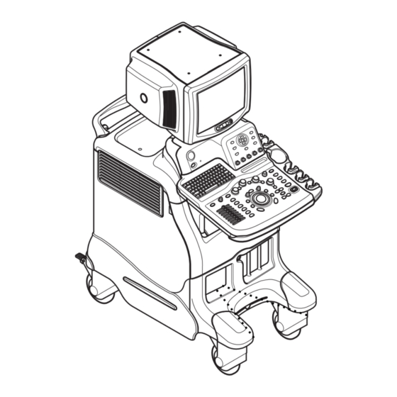
GE M EDICAL YSTEMS 2380207, R LOGIQ™ 5 PRO S IRECTION EVISION ERVICE ANUAL 1-3-3 Mechanical Safety (cont’d) NOTE: Special care should be taken when transporting the unit in a vehicle: • Secure the unit in an upright position. •... - Page 32 GE M EDICAL YSTEMS 2380207, R LOGIQ™ 5 PRO S IRECTION EVISION ERVICE ANUAL 1-3-5 Label Locations NOTE: For the symbols shown in the illustration below, refer to previous pages in this chapter. Figure 1-1 OUTSIDE MARKINGS OF LOGIQ™ 5 PRO (Monitor) 1.) Caution for Possible injury : “Never put any device onto the Monitor”...
-
Page 33: Label Locations
GE M EDICAL YSTEMS 2380207, R LOGIQ™ 5 PRO S IRECTION EVISION ERVICE ANUAL 1-3-5Label Locations (cont’d) 220-240V 500VA Max Including front printer panel Europe/USA Console (220V) 100~120V 500VA Max Including front printer panel Japan/USA/Asia Console (100~120V) Circuit Breaker Circuit Breaker... - Page 34 EDICAL YSTEMS 2380207, R LOGIQ™ 5 PRO S IRECTION EVISION ERVICE ANUAL 1-3-5Label Locations (cont’d) GE ULTRASOUND KOREA LTD. LOGIQ 5 PRO 1250VA LOGIQ 5 PRO GE ULTRASOUND KOREA 1250VA LOGIQ 5 PRO 120V 1250VA GE ULTRASOUND Korea LOGIQ 5 PRO...
-
Page 35: Lockout/Tagout Requirements (For Usa Only)
GE M EDICAL YSTEMS 2380207, R LOGIQ™ 5 PRO S IRECTION EVISION ERVICE ANUAL 1-3-6 Dangerous Procedure Warnings Warnings, such as the examples below, precede potentially dangerous procedures throughout this manual. Instructions contained in the warnings must be followed. DANGEROUS VOLTAGES, CAPABLE OF CAUSING DEATH, ARE PRESENT DANGER IN THIS EQUIPMENT. -
Page 36: Electromagnetic Compatibility
GE M EDICAL YSTEMS 2380207, R LOGIQ™ 5 PRO S IRECTION EVISION ERVICE ANUAL Section 1-4 EMC, EMI, and ESD 1-4-1 Electromagnetic Compatibility (EMC) Electromagnetic compatibility describes a level of performance of a device within its electromagnetic environment. This environment consists of the device itself and its surroundings including other equipment, power sources and persons with which the device must interface. -
Page 37: Customer Assistance
Milwaukee, WI 53219 1-262-524-5698 Customer Answer Center Fax: +1-414-647-4125 Europe Tel: +49 212 2802 208 GE Ultraschall Deutschland GmbH& Co. KG +49 212 2802 207 BeethovenstraBe 239 Postfach 11 05 60, D-42665 Solingen Germany Fax: +49 212 2802 431 Tel: +65 291-8528... - Page 38 GE M EDICAL YSTEMS 2380207, R LOGIQ™ 5 PRO S IRECTION EVISION ERVICE ANUAL 1-5-2 System Manufacturer Table 1-8 System Manufacturer Manufacturer FAX Number GE Ultrasound Korea 462-120 65-1, Sangdaewon-dong, Joong-won-Gu, 82-31-740-6436 Seongnam-Si, Gyeonggi-do, Korea 1-20 Section 1-5 - Customer Assistance...
- Page 39 GE M EDICAL YSTEMS 2380207, R LOGIQ™5 PRO S IRECTION EVISION ERVICE ANUAL Chapter 2 Pre-Installation Section 2-1 Overview 2-1-1 Purpose of chapter 2 This chapter provides the information required to plan and prepare for the installation of a LOGIQ™ 5 .
-
Page 40: General Console Requirements
2-2-2 Electrical Requirements NOTE: GE Medical Systems requires a dedicated power and ground for the proper operation of its Ultrasound equipment. This dedicated power shall originate at the last distribution panel before the system. Section 2-2 - General Console Requirements... -
Page 41: Electrical Requirements
GE M EDICAL YSTEMS 2380207, R LOGIQ™5 PRO S IRECTION EVISION ERVICE ANUAL 2-2-2 Electrical Requirements (cont’d) Sites with a mains power system with defined Neutral and Live: The dedicated line shall consist of one phase, a neutral (not shared with any other circuit), and a full size ground wire from the distribution panel to the Ultrasound outlet. -
Page 42: Emi Limitations
ERVICE ANUAL 2-2-2-5 Unit Power Plug If the unit arrives without the power plug, or with the wrong plug, you must contact your GE dealer or the installation engineer must supply what is locally required. 2-2-2-6 Power Stability Requirements Voltage drop-out Max 10 ms. -
Page 43: Scan Probe Environmental Requirements
Never place a label where RF gaskets meet the unit. Otherwise, the gap created will permit gaskets touch metal RF leakage. Or, if a label has been found in such a position, move the label. Use GE specified harnesses The interconnect cables are grounded and require ferrite beads and other shielding. Also, and peripherals cable length, material, and routing are all important;... -
Page 44: Facility Needs
2-3-2 Required Features NOTE: GE Medical Systems requires a dedicated power and ground for the proper operation of its Ultrasound equipment. This dedicated power shall originate at the last distribution panel before the system. Sites with a mains power system with defined Neutral and Live: The dedicated line shall consist of one phase, a neutral (not shared with any other circuit), and a full size ground wire from the distribution panel to the Ultrasound outlet. - Page 45 GE M EDICAL YSTEMS 2380207, R LOGIQ™5 PRO S IRECTION EVISION ERVICE ANUAL NOTE: The LOGIQ™ 5 has four outlets inside the unit. One is for the monitor and three for on board peripherals. • Power outlets for other medical equipment and gel warmer •...
-
Page 46: Desirable Features
Emergency oxygen supply • Storage for linens and equipment • Nearby waiting room, lavatory, and dressing room • Dual level lighting (bright and dim) • Lockable cabinet ordered by GE for its software and proprietary manuals. Section 2-3 - Facility Needs... -
Page 47: Recommended And Alternate Ultrasound Room Layout
GE M EDICAL YSTEMS 2380207, R LOGIQ™5 PRO S IRECTION EVISION ERVICE ANUAL 2-3-4 Recommended and Alternate Ultrasound Room Layout Recommended standard floor plan and a minimal floor plan for ultrasound equipment: DEDICATED ALALOG TELEPHONE LINE FOR CONNECTION TO INSITE 18 IN. - Page 48 GE M EDICAL YSTEMS 2380207, R LOGIQ™5 PRO S IRECTION EVISION ERVICE ANUAL 2-3-5 Networking Pre-installation Requirements 2-3-5-1 Purpose of DICOM Network Function DICOM services provide the operator with clinically useful features for moving images and patient information over a hospital network. Examples of DICOM services include the transfer of images to workstations for viewing or transferring images to remote printers.
- Page 49 GE M EDICAL YSTEMS 2380207, R LOGIQ™5 PRO S IRECTION EVISION ERVICE ANUAL 2-3-5-2 DICOM Option Pre-installation Requirements (cont’d) LOGIQ™ 5 IP Address Local Port Host Name AE Title Net Mask ROUTING INFORMATION GATEWAY IP Addresses Destination IP Addresses Default...
- Page 50 GE M EDICAL YSTEMS 2380207, R LOGIQ™5 PRO S IRECTION EVISION ERVICE ANUAL 2-12 Section 2-3 - Facility Needs...
- Page 51 GE M EDICAL YSTEMS 2380207, R LOGIQ™ 5 PRO S IRECTION EVISION ERVICE ANUAL Chapter 3 Installation Section 3-1 Overview 3-1-1 Purpose of Chapter 3 This chapter contains information needed to install the unit. Included are references to a procedure that describes how to receive and unpack the equipment and how to file a damage or loss claim.
-
Page 52: Average Installation Time
GE M EDICAL YSTEMS 2380207, R LOGIQ™ 5 PRO S IRECTION EVISION ERVICE ANUAL Section 3-2 Installation Reminders 3-2-1 Average Installation Time Table 3-2 Average Installation Time Description Average Installation Time Comments 0.5 hour Unpacking the scanner 0.5 hour Scanner wo/options Dependant on the configuration that is required 0.5 hour... - Page 53 GE M EDICAL YSTEMS 2380207, R LOGIQ™ 5 PRO S IRECTION EVISION ERVICE ANUAL 3-2-3 Safety Reminders WHEN USING ANY TEST INSTRUMENT THAT IS CAPABLE OF OPENING THE DANGER AC GROUND LINE (I.E., METER’S GROUND SWITCH IS OPEN), DON’T TOUCH THE UNIT! Two people should unpack the unit because of its weight.
- Page 54 GE M EDICAL YSTEMS 2380207, R LOGIQ™ 5 PRO S IRECTION EVISION ERVICE ANUAL Section 3-3 Receiving and Unpacking the Equipment When a new system arrives, check that any components are not damaged and are not in short supply. If shipping damage or shortage occurs, contact the address shown in Chapter 1.
- Page 55 GE M EDICAL YSTEMS 2380207, R LOGIQ™ 5 PRO S IRECTION EVISION ERVICE ANUAL Section 3-3 Receiving and Unpacking the Equipment (cont’d) 2.) Lift the TOP COVER up and off. Top Cover Figure 3-8 Removing the top Cover Chapter 3 Installation...
- Page 56 GE M EDICAL YSTEMS 2380207, R LOGIQ™ 5 PRO S IRECTION EVISION ERVICE ANUAL Section 3-3 Receiving and Unpacking the Equipment (cont’d) 3.) Remove the MONITOR CAP up and off.. Monitor Cap Figure 3-9 Removing the monitor cap 3 - 6...
- Page 57 GE M EDICAL YSTEMS 2380207, R LOGIQ™ 5 PRO S IRECTION EVISION ERVICE ANUAL Section 3-3 Receiving and Unpacking the Equipment (cont’d) 4.) Remove the three PLASTIC JOINTs from the OUTER SLEEVE 5.) Remove the OUTER SLEEVE. 6.) Remove the INNER SLEEVE.
- Page 58 GE M EDICAL YSTEMS 2380207, R LOGIQ™ 5 PRO S IRECTION EVISION ERVICE ANUAL Section 3-3 Receiving and Unpacking the Equipment (cont’d) 7.) Remove the PLASTIC BAG. 8.) Lift the Monitor up by pressing the UP/Down Release Button. 9.) Remove the MONITOR SUPPORTER.
-
Page 59: Moving Into Position
GE M EDICAL YSTEMS 2380207, R LOGIQ™ 5 PRO S IRECTION EVISION ERVICE ANUAL 3-3-1 Moving into Position Do not lift the unit by the Keyboard. CAUTION Do not tilt the unit more than 5 degrees to avoid tipping it over. -
Page 60: Preparing For Installation
GE M EDICAL YSTEMS 2380207, R LOGIQ™ 5 PRO S IRECTION EVISION ERVICE ANUAL 3-4-2 Physical Inspection 3-4-2-1 System Voltage Settings Verify that the scanner is set to the correct voltage. The Voltage settings for the LOGIQ™ 5 PRO Scanner is found on a label to the right of the Power switch and External I/O, on the rear of the system.For the Rating Plate example, refer to... -
Page 61: Completing The Installation
GE M EDICAL YSTEMS 2380207, R LOGIQ™ 5 PRO S IRECTION EVISION ERVICE ANUAL Section 3-5 Completing the Installation 3-5-1 Power On/Boot Up NOTE: After turning off the system, wait at least ten seconds before turning it on again. The system may not be able to boot if power is recycled too quickly. - Page 62 GE M EDICAL YSTEMS 2380207, R LOGIQ™ 5 PRO S IRECTION EVISION ERVICE ANUAL 3-5-1-1 Scanner Power On (cont’d) Serial Composite B/W Printer Power Figure 3-14 Power On/Off Switch Location 3-5-1-2 Power Up Sequence 1.) The Start Up Screen will be shown on the Monitor display when the system is turned ON.
- Page 63 GE M EDICAL YSTEMS 2380207, R LOGIQ™ 5 PRO S IRECTION EVISION ERVICE ANUAL 3-5-1-3 Maintanance Mode for Service 1.) If the service dongle is inserted in the USB port in the rear panel during system boot up, Maintenance access window appears.
-
Page 64: Power Off/ Shutdown
GE M EDICAL YSTEMS 2380207, R LOGIQ™ 5 PRO S IRECTION EVISION ERVICE ANUAL 3-5-2 Power Off/ Shutdown NOTE: After turning off a system, wait at least ten seconds before turning it on again. The system may not be able to boot if power is recycled too quickly. -
Page 65: Transducer Connection
GE M EDICAL YSTEMS 2380207, R LOGIQ™ 5 PRO S IRECTION EVISION ERVICE ANUAL 3-5-3 Transducer Connection 1.) Connect a transducer to one of the three rightmost transducer receptacle as follows: A.) Ensure that the transducer twist lock lever to the horizontal position. -
Page 66: System Specifications
GE M EDICAL YSTEMS 2380207, R LOGIQ™ 5 PRO S IRECTION EVISION ERVICE ANUAL Section 3-6 System Configuration 3-6-1 System Specifications 3-6-1-1 System Settings Table 3-1 System Configuration Configuration Category Description Enables the user or service personnel to set the... - Page 67 GE M EDICAL YSTEMS 2380207, R LOGIQ™ 5 PRO S IRECTION EVISION ERVICE ANUAL 3-6-1-1 System Settings (cont’d) 5.) Press Utility > System. 6.) Set the Hospital name, Department, Date and Time, Language, and Units. Figure 3-20 Setting Display Click on Utilities to terminate the utility function.
-
Page 68: Electrical Specifications
GE M EDICAL YSTEMS 2380207, R LOGIQ™ 5 PRO S IRECTION EVISION ERVICE ANUAL 3-6-1-2 Physical Dimensions (cont’d) WEIGHT 180Kg (397lbs) including Monitor NOTE Length is in mm Variation +/- 10% Serial Composite B/W Printer Power Figure 3-21 Overall Dimensions... -
Page 69: On-Board Optional Peripherals
GE M EDICAL YSTEMS 2380207, R LOGIQ™ 5 PRO S IRECTION EVISION ERVICE ANUAL 3-6-3 On-Board Optional Peripherals Table 3-5 List of Recording Devices Device Manufacturer Model Video Signal UP-895MDW NTSC/PAL B/W Video Printer SONY UPD-895 P-91(AP9500) NTSC P91W NTSC/PAL... -
Page 70: External I/O Connector Panel
GE M EDICAL YSTEMS 2380207, R LOGIQ™ 5 PRO S IRECTION EVISION ERVICE ANUAL 3-6-4 External I/O Connector Panel (cont’d) This section indicates the pin assignment for each connector. Serial 220-240V 500VA Max Including front printer panel Figure 3-22 Rear Connector Panel NOTE: Each outer (case) ground line of peripheral/accessory connectors are protectively grounded. - Page 71 GE M EDICAL YSTEMS 2380207, R LOGIQ™ 5 PRO S IRECTION EVISION ERVICE ANUAL 3-6-4-1 External I/O Pin Outs Pin No. Signal Pin No. Signal Table 3-6 Pin Assignments of RS232C for Remote 1 and Remote 2 Pin No. Signal Pin No.
- Page 72 GE M EDICAL YSTEMS 2380207, R LOGIQ™ 5 PRO S IRECTION EVISION ERVICE ANUAL 3-6-4-1 External I/O Pin Outs (cont’d) Pin No. Signal Pin No. Signal +5 VDC DATA + DATA - Table 3-9 Pin Assignments of USB Pin No.
-
Page 73: Video Specification
GE M EDICAL YSTEMS 2380207, R LOGIQ™ 5 PRO S IRECTION EVISION ERVICE ANUAL 3-6-5 Video Specification Video specifications may be needed to be able to connect laser cameras or other devices to the LOGIQ™ 5 PRO. Table 3-14 Video Specifications... -
Page 74: Software/Option Configuration
GE M EDICAL YSTEMS 2380207, R LOGIQ™ 5 PRO S IRECTION EVISION ERVICE ANUAL Section 3-7 Available Probes See Specifications in the LOGIQ™ 5 PRO User Reference Manual for probes and intended use. See Chapter 9, for part numbers to be used when ordering new or replacement probes. - Page 75 GE M EDICAL YSTEMS 2380207, R LOGIQ™ 5 PRO S IRECTION EVISION ERVICE ANUAL Section 3-9 Connectivity Installation Worksheet Site System Information Comments: Floor: Site: Dept.: Room: LOGIQ SN: Type: REV: CONTACT INFORMATION Name Title Phone E-Mail Address TCP/IP Settings...
-
Page 76: Product Locator Installation
3-10-2 User Manual(s) Check that the correct User Manual(s) for the system and software revision, is included with the installation. Specific language versions of the User Manual may also be available. Check with your GE Sales Representative for availability. 3-10-2-1 Reference off-board peripherals and options None. - Page 77 GE M EDICAL YSTEMS 2380207, R LOGIQ™ 5 PRO S IRECTION EVISION ERVICE ANUAL Chapter 4 Functional Checks Section 4-1 Overview 4-1-1 Purpose of Chapter 4 This chapter provides procedures for quickly checking major functions of the LOGIQ™ 5 PRO scanner diagnostics by using the built-in service software, and power supply adjustments.
-
Page 78: General Procedure
GE M EDICAL YSTEMS 2380207, R LOGIQ™ 5 PRO S IRECTION EVISION ERVICE ANUAL Section 4-3 General Procedure SYSTEM REQUIRES ALL COVERS CAUTION Operate this unit only when all board covers and frame panels are securely in place. The covers are required for safe operation, good system performance and cooling purposes. - Page 79 GE M EDICAL YSTEMS 2380207, R LOGIQ™ 5 PRO S IRECTION EVISION ERVICE ANUAL 4-3-1-1 Scanner Power On (cont’d) Main Circuit Breaker Main Power Cable Figure 4-24 Circuit Breaker NOTE: When power is applied to the Scanner, and the Rear Circuit breaker is turned ON, Power is distributed to the ATX smps in the Back End Processor and Power control circuit in the AC power assy .
-
Page 80: Power Off / Shutdown
GE M EDICAL YSTEMS 2380207, R LOGIQ™ 5 PRO S IRECTION EVISION ERVICE ANUAL 4-3-1-1 Scanner Power On (cont’d) 5.) Press the ON/OFF key at the front of the System once. Serial Composite B/W Printer Power Figure 4-25 Power On/Off Standby Switch Location... -
Page 81: System Features
GE M EDICAL YSTEMS 2380207, R LOGIQ™ 5 PRO S IRECTION EVISION ERVICE ANUAL 4-3-2-2 Switch off the scanner 1.) Switch OFF the Circuit Breaker at the back of the scanner. 2.) Disconnect the Mains Power Cable is necessary. For example: Servicing or relocating the scanner. - Page 82 GE M EDICAL YSTEMS 2380207, R LOGIQ™ 5 PRO S IRECTION EVISION ERVICE ANUAL 4-3-3-1 Control Panel (cont’d) 10.)Imaging Feature Keys 11.)Freeze 12.)Probe and Cord Holder 13.)Gel Holder 14.)New Patient 15.)Application 16.)Report 17.)End Exam 18.)Mode Parameter 19.)Utility 20.)Top Menu control keys 21.)Submenu control keys...
- Page 83 1. Institution/Hospital Name, Date, Time, Operator 2. Probe Identifier, Exam Study Identification 3. Patient Name, Patient Identification 4. GE Symbol : Probe Orientation Marker. Coincides with a probe orientation marking on the probe. 5. Image Preview 6. Gray/Color Bar 7. Cine Gauge 8.
-
Page 84: System B/M-Mode Checks
GE M EDICAL YSTEMS 2380207, R LOGIQ™ 5 PRO S IRECTION EVISION ERVICE ANUAL 4-3-4 System B/M-Mode Checks For a basic functional check of the system’s different modes, the Quick Guide will familiarize you with image optimization for B-Mode, M-Mode, Color Flow, and Doppler. -
Page 85: System Cfm And Pwd Checks
GE M EDICAL YSTEMS 2380207, R LOGIQ™ 5 PRO S IRECTION EVISION ERVICE ANUAL 4-3-5 System CFM and PWD Checks Table 4-18 CFM and PWD Functions Adjusts the baseline to accommodate faster or slower blood Baseline flows to eliminate aliasing. -
Page 86: Basic Measurements
GE M EDICAL YSTEMS 2380207, R LOGIQ™ 5 PRO S IRECTION EVISION ERVICE ANUAL 4-3-6 Basic Measurements NOTE: The following instructions assume that you first scan the patient and then press Freeze. 4-3-6-1 Distance and Tissue Depth Measurements 1.) Press MEASURE once; an active caliper displays. - Page 87 GE M EDICAL YSTEMS 2380207, R LOGIQ™ 5 PRO S IRECTION EVISION ERVICE ANUAL 4-3-6-3 Worksheets Measurement/Calculation worksheets are available to display and edit measurements and calculations. There are generic worksheets as well as Application specific worksheets. The worksheets are selected from the Measurement icon on the monitor screen after pressing measurement key.
-
Page 88: Probe/Connectors Usage
GE M EDICAL YSTEMS 2380207, R LOGIQ™ 5 PRO S IRECTION EVISION ERVICE ANUAL 4-3-7 Probe/Connectors Usage 4-3-7-1 Connecting a probe 1.) Place the probe's carrying case on a stable surface and open the case. 2.) Carefully remove the probe and unwrap the probe cable. -
Page 89: Using Cine
GE M EDICAL YSTEMS 2380207, R LOGIQ™ 5 PRO S IRECTION EVISION ERVICE ANUAL 4-3-8 Using Cine 4-3-8-1 Activating CINE Press FREEZE, then roll the TRACKBALL to activate CINE. To start CINE Loop playback, press the left most button on the menu key panel of keyboard. To stop CINE Loop playback. press Run/Stop. -
Page 90: Using The Cd-Rw / Mod (Magneto-Optical Drive)
GE M EDICAL YSTEMS 2380207, R LOGIQ™ 5 PRO S IRECTION EVISION ERVICE ANUAL 4-3-10 Using the CD-RW / MOD (Magneto-Optical Drive) 4-3-10-1 Using the CD-RW Never move the unit with a disk in the CD-RW because the drive actuator will not be locked NOTICE and the CD-RW could break. - Page 91 GE M EDICAL YSTEMS 2380207, R LOGIQ™ 5 PRO S IRECTION EVISION ERVICE ANUAL 4-3-10-2 Using the MOD (Magneto-Optical Drive) The 3.5 inch Magneto-Optical disk drive supports the following densities: Standard: 1.3GB; 640MB; 540MB; 230MB; and 128MB Overwrite: 1.3GB; 640MB; and 540MB 1.) Before installing an MO disk in the MOD, check the MO disk for loose hardware or damaged labels...
- Page 92 GE M EDICAL YSTEMS 2380207, R LOGIQ™ 5 PRO S IRECTION EVISION ERVICE ANUAL 4-3-11 Backup and Restore Database, Preset Configurations and Images Avoid mechanical ejection whenever possible. Mechanical ejection leaves the actuator NOTICE unlocked and the MOD susceptible to damage if moved. If forced to use this method, reboot the system, then insert and eject a known good disk using one of the other manual ejection methods.
- Page 93 4.) On the monitor display, select BACKUP/RESTORE. NOTE: If you are not logged in as GE Service or with administrator privileges, the Operator Login window is displayed. Log on with administrator privileges. 5.) In the Backup list, select Patient Archive, Report Archive, System Configuration and User Defined Configuration.
- Page 94 GE M EDICAL YSTEMS 2380207, R LOGIQ™ 5 PRO S IRECTION EVISION ERVICE ANUAL 4-3-11-3 Restore System Presets and Configurations The restore procedure overwrites the existing database on the local hard drive. Make sure to insert CAUTION the correct MOD or CD-R.
- Page 95 GE M EDICAL YSTEMS 2380207, R LOGIQ™ 5 PRO S IRECTION EVISION ERVICE ANUAL 4-3-11-4 Archiving Images To export an exam(s) to a compatible Ultrasound system: 1.) Format the removable media (MOD or CD-ROM). Label the removable media. Answer Yes/OK to the messages.Press Patient.
- Page 96 GE M EDICAL YSTEMS 2380207, R LOGIQ™ 5 PRO S IRECTION EVISION ERVICE ANUAL 4-3-11-4 Archiving Images (cont’d) 4.) In the patient list at the top of the Patient menu, select the patient(s) you want to export. You can use Windows commands to select more than one patient. To select a consecutive list of patients, click the cursor on the first name, move the cursor to the last name, then press and hold down the Shift+right Set key to select all the names.
- Page 97 GE M EDICAL YSTEMS 2380207, R LOGIQ™ 5 PRO S IRECTION EVISION ERVICE ANUAL 4-3-12 ECG Check Out (this option is currently not available on the LOGIQ™ 5 PRO Connect the ECG Harness and check: Table 4-19 ECG Harness Check...
-
Page 98: Software Configuration Checks
GE M EDICAL YSTEMS 2380207, R LOGIQ™ 5 PRO S IRECTION EVISION ERVICE ANUAL Section 4-4 Application Turnover Checklist Complete these checks before returning the scanner to customer for use: 1.) TBD Section 4-5 Software Configuration Checks Table 4-20 Software Configuration Checks... - Page 99 GE M EDICAL YSTEMS 2380207, R LOGIQ™ 5 PRO S IRECTION EVISION ERVICE ANUAL Section 4-6 Peripheral Checks Check that peripherals work as described below: Table 4-21 Peripheral Checks Step Task to do Expected Result(s) Press (FREEZE) Stop image acquisition.
- Page 100 GE M EDICAL YSTEMS 2380207, R LOGIQ™ 5 PRO S IRECTION EVISION ERVICE ANUAL Section 4-7 Site Log Table 4-22 Site Log Date Service person Problem Comments 4 - 24 Section 4-7 - Site Log...
- Page 101 GE M EDICAL YSTEMS 2380207, R LOGIQ™ 5 PRO S IRECTION EVISION ERVICE ANUAL Section 4-8 Software Configuration Checks Refer to Chapter 3, Section 3-6 - System Configuration for setting procedures. Table 4-23 Software Configuration Checks Step Task to do...
- Page 102 GE M EDICAL YSTEMS 2380207, R LOGIQ™ 5 PRO S IRECTION EVISION ERVICE ANUAL Section 4-10Monitor Function Checks 4-10-1 CRT Assy function check procedure 1.) Turn on the system and check the completion of Echoloader loading. 2.) Select "Utility Key" on the Key board and then choose " Test Pattern" and "Resolution" marked in Figure 4-40.
- Page 103 GE M EDICAL YSTEMS 2380207, R LOGIQ™ 5 PRO S IRECTION EVISION ERVICE ANUAL 4-10-4 Rear panel Assy function check procedure 1.) Turn on the system and check the completion of Echoloader loading. 2.) Refer to See “Peripheral Checks” on page 4-21.
- Page 104 GE M EDICAL YSTEMS 2380207, R LOGIQ™ 5 PRO S IRECTION EVISION ERVICE ANUAL Section 4-11Keyboard Function Checks 4-11-1 Main Keyboard Assy validation 1.) Boot up the system 2.) Insert the Service Dongle and go to the maintenance mode. 3.) Click 'Start' and go to 'Run' .
- Page 105 GE M EDICAL YSTEMS 2380207, R LOGIQ™ 5 PRO S IRECTION EVISION ERVICE ANUAL 4-11-1 Main Keyboard Assy validation (cont’d) 6.) Write the 'scfpapitest.exe' on the command prompt and press 'Enter' button to pop up the scfpapitest program. Figure 4-45 scfpapitest program 7.) Press the keyboard button and rotate rotary button.
- Page 106 GE M EDICAL YSTEMS 2380207, R LOGIQ™ 5 PRO S IRECTION EVISION ERVICE ANUAL Button or Button or Rotary Name The Name displayed in Log Rotary Name The Name displayed in Log Reverse Reverse Button PDI Button Print or record button1...
- Page 107 GE M EDICAL YSTEMS 2380207, R LOGIQ™ 5 PRO S IRECTION EVISION ERVICE ANUAL 4-11-1 Main Keyboard Assy validation (cont’d) 8.) Check the 'Fast' radio button into Indicator box on scfpapitest program and press 'Set All' button. Figure 4-46 Fast button After pressing Fast radio button, indicators should be blanked on the frontpanel.
- Page 108 GE M EDICAL YSTEMS 2380207, R LOGIQ™ 5 PRO S IRECTION EVISION ERVICE ANUAL 4-11-2 OP Panel Encoder Assy Validation 1.) Follow up the procedure 8-4-1 to run the scfpapitest program. 2.) Check the each Encoder in Table 4-25 on page 29.
- Page 109 GE M EDICAL YSTEMS 2380207, R LOGIQ™ 5 PRO S IRECTION EVISION ERVICE ANUAL 4-11-8 OP Panel LCD Assy Validation 1.) Boot up the system. 2.) Follow up the process from step1 to step7 of Section 4-11-1. 3.) Touch the touchpanel.
- Page 110 GE M EDICAL YSTEMS 2380207, R LOGIQ™ 5 PRO S IRECTION EVISION ERVICE ANUAL 4-11-9 OP Panel LCD Encoder Assy Validation 1.) Boot up the system and run the scfpapitest program. Follow up the procedure from step 1 to step 7 of Section 4-11-1 to run the scfpapitest program.
- Page 111 GE M EDICAL YSTEMS 2380207, R LOGIQ™ 5 PRO S IRECTION EVISION ERVICE ANUAL 4-11-10 Menu Key Assy 1.) Boot up the system and run the scfpapitest program. Follow up the procedure from step 1 to step 7 of Section 4-11-1 to run the scfpapitest program.
- Page 112 GE M EDICAL YSTEMS 2380207, R LOGIQ™ 5 PRO S IRECTION EVISION ERVICE ANUAL 4-11-11 Menu Encoder Assy 1.) Boot up the system and run the scfpapitest program. Follow up the procedure from step 1 to step 7 of Section 4-11-1 to run the scfpapitest program.
- Page 113 GE M EDICAL YSTEMS 2380207, R LOGIQ™ 5 PRO S IRECTION EVISION ERVICE ANUAL 4-11-12 Speaker Assy Validation 1.) Boot up the system 2.) Insert the Service Dongle and go to the maintenance mode. 3.) Move to trackball to the bottom of main monitor.
- Page 114 GE M EDICAL YSTEMS 2380207, R LOGIQ™ 5 PRO S IRECTION EVISION ERVICE ANUAL 4-11-12 Speaker Assy Validation (cont’d) 6.) At the Balance in Volume Control, move the gauge to the max left. Figure 4-51 Volume control for left speaker 7.) Move the Volume gauge up and down.
- Page 115 GE M EDICAL YSTEMS 2380207, R LOGIQ™ 5 PRO S IRECTION EVISION ERVICE ANUAL Section 4-12 Mechanical Function Checks 4-12-1 Cover Parts Function Validation Table 4-29 Cover parts of the FRU Item Right and Left cover Front cover Rear cover...
- Page 116 GE M EDICAL YSTEMS 2380207, R LOGIQ™ 5 PRO S IRECTION EVISION ERVICE ANUAL 4-12-1-1 Task Lamp Assy Check if task lamp is operated. Figure 4-53 Task Lamp Assy 4-12-1-2 Keyboard Front Grip • Check if the keyboard front grip is fastened so that it won't move.
- Page 117 GE M EDICAL YSTEMS 2380207, R LOGIQ™ 5 PRO S IRECTION EVISION ERVICE ANUAL 4-12-1-4 Gas Spring Assy Check if the up and down mechanism operates rightly. Figure 4-56 Gas Spring Assy 4-12-1-5 Front caster/Rear caster • Check caster locks for proper operation.
- Page 118 GE M EDICAL YSTEMS 2380207, R LOGIQ™ 5 PRO S IRECTION EVISION ERVICE ANUAL 4-12-1-6 Bumper Set • Check if the bumper set is fastened so that it won't move. • Check if the bumper set can not be removed easily.
- Page 119 GE M EDICAL YSTEMS 2380207, R LOGIQ™ 5 PRO S IRECTION EVISION ERVICE ANUAL 4-12-1-8 OP Panel Encoder Assy, TGC Knob Set, OP Panel LCD Encoder Assy, Menu Encoder Assy • Check if the each button operates properly. • Check if encoder knobs are in the center.
- Page 120 GE M EDICAL YSTEMS 2380207, R LOGIQ™ 5 PRO S IRECTION EVISION ERVICE ANUAL 4-12-1-9 Monitor Cover Set • Check if the FRU parts are assembled tightly by naked eye and hands. • Check if there are dents, scratches, or cracks on the FRU parts.
- Page 121 GE M EDICAL YSTEMS 2380207, R LOGIQ™ 5 PRO S IRECTION EVISION ERVICE ANUAL Section 4-13Board Function Checks 4-13-1 RLY Assy function check procedure 1.) Turn on the system 2.) After completion of echoloader loading, connect probe on port1. See “Connecting a probe” on page 4-11.
- Page 122 GE M EDICAL YSTEMS 2380207, R LOGIQ™ 5 PRO S IRECTION EVISION ERVICE ANUAL 4-13-2 LMT Assy function check procedure 1.) Turn on the system and check the completion of Echoloader loading. 2.) Check the system basic functions. Refer to Section 4-3-4 - System B/M-Mode Checks on page 4- 7.
- Page 123 GE M EDICAL YSTEMS 2380207, R LOGIQ™ 5 PRO S IRECTION EVISION ERVICE ANUAL 4-13-4 RDS Assy function check procedure 1.) Turn on the system and check the completion of Echoloader loading. 2.) Do the Service Login. Refer to the Section 5-10-2-2 - Service Login on page 5-42.
- Page 124 GE M EDICAL YSTEMS 2380207, R LOGIQ™ 5 PRO S IRECTION EVISION ERVICE ANUAL 4-13-5 ATD Assy function check procedure 1.) Turn on the system and check the completion of Echoloader loading. 2.) Do the Service Login. Refer to the Section 5-10-2-2 - Service Login on page 5-42.
- Page 125 GE M EDICAL YSTEMS 2380207, R LOGIQ™ 5 PRO S IRECTION EVISION ERVICE ANUAL 4-13-6 FECII Assy function check procedure 1.) Turn on the system and check the completion of Echoloader loading. 2.) Do the Service Login. Refer to the Section 5-10-2-2 - Service Login on page 5-42.
- Page 126 GE M EDICAL YSTEMS 2380207, R LOGIQ™ 5 PRO S IRECTION EVISION ERVICE ANUAL 4-13-7 CWDOP Assy function check procedure 1.) Turn on the system and check the completion of Echoloader loading. 2.) Do the Service Login. Refer to the Section 5-10-2-2 - Service Login on page 5-42.
-
Page 127: Power On/Boot Up
GE M EDICAL YSTEMS 2380207, R LOGIQ™ 5 PRO S IRECTION EVISION ERVICE ANUAL 4-13-8 Backplane Assy function check procedure 1.) Turn on the system and check the completion of Echoloader loading. 2.) Check the system basic functions. Refer to Section 4-3-4 - System B/M-Mode Checks on page 4- 7. - Page 128 GE M EDICAL YSTEMS 2380207, R LOGIQ™ 5 PRO S IRECTION EVISION ERVICE ANUAL 4-13-11 BEP Assy function check procedure 4-13-11-1 HDD, Memory, CPU Diagnositc Test 1.) The Start up Screen will be shown on the Monitor display when the system is Turned ON.
- Page 129 GE M EDICAL YSTEMS 2380207, R LOGIQ™ 5 PRO S IRECTION EVISION ERVICE ANUAL 4-13-11-1 HDD, Memory, CPU Diagnositc Test (cont’d) 6.) Memory Test Select Memory test manu, start to testing Check display 'Pass' massage Figure 4-71 Memory Test 7.) CPU Test...
- Page 130 GE M EDICAL YSTEMS 2380207, R LOGIQ™ 5 PRO S IRECTION EVISION ERVICE ANUAL 4-13-11-2 Basic Function Test 1.) Turn on the system and check the completion of Echoloader loading. 2.) Check the system basic functions. Refer to Section 4-3-4 - System B/M-Mode Checks on page 4- 7.
- Page 131 GE M EDICAL YSTEMS 2380207, R LOGIQ™ 5 PRO S IRECTION EVISION ERVICE ANUAL 4-13-12 VIC Assy function check procedure 1.) Turn on the system and check the completion of Echoloader loading. 2.) Do the Service Login. Refer to the Section 5-10-2-2 - Service Login on page 5-42.
- Page 132 GE M EDICAL YSTEMS 2380207, R LOGIQ™ 5 PRO S IRECTION EVISION ERVICE ANUAL 4-13-13 SMPS, HDD, ODD Assy function check procedure 4-13-13-1 SMPS Assy Test 1.) Turn on the system and check the completion of Echoloader loading. 2.) Check the system basic functions. Refer to Section 4-3-4 - System B/M-Mode Checks on page 4- 7.
- Page 133 GE M EDICAL YSTEMS 2380207, R LOGIQ™ 5 PRO S IRECTION EVISION ERVICE ANUAL 4-13-14 PC2IP Assy function check procedure. 1.) Turn on the system and check the completion of Echoloader loading. 2.) Do the Service Login. Refer to the Section 5-10-2-2 - Service Login on page 5-42.
- Page 134 GE M EDICAL YSTEMS 2380207, R LOGIQ™ 5 PRO S IRECTION EVISION ERVICE ANUAL 4-13-15 AC Power Assy function check procedure. 1.) Turn on the system and check the completion of Echoloader loading. 2.) Check the system basic functions. Refer to Section 4-3-4 - System B/M-Mode Checks on page 4- 7.
-
Page 135: Front End
GE M EDICAL YSTEMS 2380207, R LOGIQ™5 PRO S IRECTION EVISION ERVICE ANUAL Chapter 5 Components and Functions (Theory) Section 5-1 Overview 5-1-1 Purpose of Chapter 5 This chapter explains LOGIQ™ 5 PRO’s system concepts, component arrangement, and subsystem function. It also describes the Power Distribution System (PDS) and probes. - Page 136 GE M EDICAL YSTEMS 2380207, R LOGIQ™5 PRO S IRECTION EVISION ERVICE ANUAL Section 5-2 General Information LOGIQ™ 5 PRO is a phased and linear array ultrasound imaging scanner. It has provisions for analog input sources like ECG. A Doppler probe may also be connected and used.
- Page 137 GE M EDICAL YSTEMS 2380207, R LOGIQ™5 PRO S IRECTION EVISION ERVICE ANUAL Section 5-3 Block Diagram SIG Assy PMT Assy VCA2613 ATD Assy CWDOP VCA2613 Assy TxPulse Driver X16 VCA2613 (option) TxPulse Driver X16 VCA2613 TXIC FPGA RLY Assy(Prb VF)
- Page 138 GE M EDICAL YSTEMS 2380207, R LOGIQ™5 PRO S IRECTION EVISION ERVICE ANUAL Section 5-3 Block Diagram (cont’d) SIG Assy RDS Assy Memory FEC Assy Control Buffer 12 Bits ADC 16MB CWDOP Buffer 12 Bits ADC Assy FLASH Buffer 12 Bits ADC...
- Page 139 GE M EDICAL YSTEMS 2380207, R LOGIQ™5 PRO S IRECTION EVISION ERVICE ANUAL Section 5-4 Front End DC Power DC Power output for DC Power Input output for Keyboard(15V,5V) AC Power Input (3.3V, 6V,-6V, FAN(15v) (110V) 15V,-15V,5V) for HV Back plane Board...
- Page 140 GE M EDICAL YSTEMS 2380207, R LOGIQ™5 PRO S IRECTION EVISION ERVICE ANUAL 5-4-1 RELAY Probe A RELAY Probe B To LMT Probe C Probe ID DCWD Control Control Temperature Probe I/F FPGA Circuit Sensor JUSC I/F Figure 5-5 RLY Block Diagram RLY ASSY contains of 3 phased array probe connectors and provides switchable connection between probes and 64ch transmitters/receivers.
- Page 141 GE M EDICAL YSTEMS 2380207, R LOGIQ™5 PRO S IRECTION EVISION ERVICE ANUAL 5-4-1-1 Interface to Probe • Probe Status detection Detects whether or not a probe is connected.(POPEN) Detects ID code of a connected probe.(PCODE) • Mux Interface Transfers control data of Mux to a probe.(CONSYS,CONSTA) Enables/Disables control of data.
- Page 142 GE M EDICAL YSTEMS 2380207, R LOGIQ™5 PRO S IRECTION EVISION ERVICE ANUAL 5-4-3 5-4-3-1 Overview Rx Ch#0 Rx Ch#32 Rx Ch#1 Rx Ch#33 Rx Ch#2 Rx Ch#34 Rx Ch#3 Rx Ch#35 Rx Ch#28 Rx Ch#60 Rx Ch#29 Rx Ch#61...
- Page 143 GE M EDICAL YSTEMS 2380207, R LOGIQ™5 PRO S IRECTION EVISION ERVICE ANUAL 5-4-4 THV High HV Switch Circuit THV Low TPG2 TPG1 ECL CLK 40M Q1 FET Driver x 16ch Tx Pulse[63:48] ECL to TIL +TxP[15:0] ECL CLK 40MQ2...
- Page 144 GE M EDICAL YSTEMS 2380207, R LOGIQ™5 PRO S IRECTION EVISION ERVICE ANUAL 5-4-5 5-4-5-1 Overview 12 Bits Channel 0 OQCARD 12 Bits Channel 7 12 Bits Channel 8 JUSC BUS FPGA OQCARD 12 Bits Channel 15 12 Bits Channel 16...
- Page 145 GE M EDICAL YSTEMS 2380207, R LOGIQ™5 PRO S IRECTION EVISION ERVICE ANUAL 5-4-5-1 Overview (cont’d) Reference Voltage Generator : This mode is for imaging. The parameters specific to scan line number are sent to OQCARDs and the start trigger for receiving signals is generated.
- Page 146 GE M EDICAL YSTEMS 2380207, R LOGIQ™5 PRO S IRECTION EVISION ERVICE ANUAL 5-4-6 (cont’d) • CLK Generator Block: Generates 40MHz (two phases), and 26.6MHz clock using 160MHz master clock. • Real Time Controller (RTCL): The TRIG cyclical Real Time Control is done by SH4 RISC processor. SH4 is a one of MID BUS agent through SH-PCI bridge.
- Page 147 GE M EDICAL YSTEMS 2380207, R LOGIQ™5 PRO S IRECTION EVISION ERVICE ANUAL 5-4-7-3 Output Signal to FEC The following signals are sent to FEC via BACKPLANE board. • OV(Over Voltage), OC(Over Current) of each power source : HV tests in itself. The result transmits the FEC via BACKPLANE ASSY.
-
Page 148: Backend Processor
GE M EDICAL YSTEMS 2380207, R LOGIQ™5 PRO S IRECTION EVISION ERVICE ANUAL Section 5-5 Backend Processor 5-5-1 BEP1 Patient IO Patient IO To Monitor To Monitor (Option) (Option) To RAI Board in Rear Panel To RAI Board in Rear Panel... - Page 149 GE M EDICAL YSTEMS 2380207, R LOGIQ™5 PRO S IRECTION EVISION ERVICE ANUAL 5-5-2 BEP2 Patient IO To Monitor (Option) To RAI Board in Rear Panel To LCD in OPIO(Keyboard) Battery Power AC 110V On B’d with P4 2.0GHz 512MB...
- Page 150 GE M EDICAL YSTEMS 2380207, R LOGIQ™5 PRO S IRECTION EVISION ERVICE ANUAL 5-5-3 BEP3 BEP3 have different motherboard and different speed of CPU than BEP2. Basic structure is same as BEP2. BEP ENCLOSURE Motherboard RS232 Parallel TO LCD in...
- Page 151 GE M EDICAL YSTEMS 2380207, R LOGIQ™5 PRO S IRECTION EVISION ERVICE ANUAL 5-5-4 BT05 BEP3 BT05 BEP3 CPU : Penium4 2.8GHz (512kb cache, 533MHZ) Figure 5-15 BT05 BEP3 Chapter 5 Components and Functions (Theory) 5-17...
- Page 152 GE M EDICAL YSTEMS 2380207, R LOGIQ™5 PRO S IRECTION EVISION ERVICE ANUAL 5-5-5 VIC Card 50p Connector 2 ports of rs232 To Rear Panel for remote control of VCR Patient IO Interface To Patient IO module in BEP Box...
- Page 153 GE M EDICAL YSTEMS 2380207, R LOGIQ™5 PRO S IRECTION EVISION ERVICE ANUAL 5-5-5-1 VIC Card I/O Signal VIC card has many of I/O signal in connectors for system on/off function and peripheral interface V G A V G A...
- Page 154 GE M EDICAL YSTEMS 2380207, R LOGIQ™5 PRO S IRECTION EVISION ERVICE ANUAL Table 5-4 Connector J2 (Peripheral Interface I/O) Signal Name (Pin No) Description Signal Path Analog Red out signal for Color printer Red Out (1) VIC -> 44p DSub Conn Cable -> Rear Panel...
- Page 155 GE M EDICAL YSTEMS 2380207, R LOGIQ™5 PRO S IRECTION EVISION ERVICE ANUAL Table 5-5 Connector J4 (Control Signal I/O) Signal Name (Pin No) Description Signal Path AC Power Switch Control Signal for Peripheral AC VIC -> 50p SCSI Conn Cable -> Rear Panel -> J6...
-
Page 156: Patient I/O (Option)
GE M EDICAL YSTEMS 2380207, R LOGIQ™5 PRO S IRECTION EVISION ERVICE ANUAL 5-5-6 Patient I/O (Option) The optional Patient I/O is mounted at the front of the BEP chassi. Available inputs: • • • AUX1 • AUX2 5-22 Section 5-5 - Backend Processor... -
Page 157: Keyboard Block
GE M EDICAL YSTEMS 2380207, R LOGIQ™5 PRO S IRECTION EVISION ERVICE ANUAL Section 5-6 Top Console The Top Console includes a On/off switch, a keyboard, different controls for manipulating the picture quality, controls for use in Measure & Analyze (M&A), and loudspeakers for stereo sound output (used during Doppler scanning, inside the CRT monitor cover). - Page 158 GE M EDICAL YSTEMS 2380207, R LOGIQ™5 PRO S IRECTION EVISION ERVICE ANUAL 5-6-1-1 KEYBOARD Signal I/O All of interface signals to console are through the HUB assy in the keyboard. The keyboard has 4 cable connectors for console interfacing. 1 USB connector and 2 connectors for other signal on HUB assy and...
- Page 159 GE M EDICAL YSTEMS 2380207, R LOGIQ™5 PRO S IRECTION EVISION ERVICE ANUAL 5-6-2 MONITOR 15 inch high resolution RGB monitor with non interlace scan includes loudspeakers for stereo sound output and microphone to record talking of operator. Monitor have also task lamp to light up the A/N key...
-
Page 160: External I/O (Rear Panel)
GE M EDICAL YSTEMS 2380207, R LOGIQ™5 PRO S IRECTION EVISION ERVICE ANUAL Section 5-7 External I/O (Rear Panel) The External I/O is the interface between the scanner and all external items, located at the rear side of the scanner. -
Page 161: Peripherals
GE M EDICAL YSTEMS 2380207, R LOGIQ™5 PRO S IRECTION EVISION ERVICE ANUAL 5-7-1 Input/Output Signals for peripheral Table 5-10 Input Output signals for peripherals Description Connection from/via/to Signal Name R/G/B/Sync for Color RGB and Sync signal output for analog color VIC ->... - Page 162 GE M EDICAL YSTEMS 2380207, R LOGIQ™5 PRO S IRECTION EVISION ERVICE ANUAL 5-7-2 Peripherals and Cable connection A VCR, a Black & White Video Printer and a Color Printer may be installed onboard the scanner. These devices are connected to the External I/O (Rear Panel) or Front Panel in the case of B/W Printer.
- Page 163 GE M EDICAL YSTEMS 2380207, R LOGIQ™5 PRO S IRECTION EVISION ERVICE ANUAL 5-7-2-2 Cable Connection - Color Printer Connect the cables listed below between the Color Printer and the console. BNC CABLE for VIDEO SIGNAL (supplied with color video printer)
- Page 164 GE M EDICAL YSTEMS 2380207, R LOGIQ™5 PRO S IRECTION EVISION ERVICE ANUAL 5-7-2-2 Cable Connection - Color Printer (cont’d) Connect the cables listed below between the Color Printer and the console. RS232C C ABLE BNC CABLE for VIDEO SI G NAL...
- Page 165 GE M EDICAL YSTEMS 2380207, R LOGIQ™5 PRO S IRECTION EVISION ERVICE ANUAL 5-7-2-2 Cable Connection - Color Printer (cont’d) Connect USB cable listed below between the SONY UP-D21MD Color Printer and the console. Rear Panel of JUPITER USB cable...
- Page 166 GE M EDICAL YSTEMS 2380207, R LOGIQ™5 PRO S IRECTION EVISION ERVICE ANUAL 5-7-2-3 Cable Connection- VCR Connect the cables listed below between the Sony VCR and the console. RS232C CABLE Rear Panel of JUPITER S. Video CABLE for VIDEO SIGNAL...
- Page 167 GE M EDICAL YSTEMS 2380207, R LOGIQ™5 PRO S IRECTION EVISION ERVICE ANUAL 5-7-2-3 Cable Connection- VCR (cont’d) Connect the cables listed below between the Panasonic VCR and the console. RS232C CABLE Rear Panel of JUPITER VIDEO IN AUDIO VIDEO OUT...
-
Page 168: Interconnect Cabling
GE M EDICAL YSTEMS 2380207, R LOGIQ™5 PRO S IRECTION EVISION ERVICE ANUAL 5-7-3 Interconnect Cabling LOGIQ5 WIRING DIAGRAM Outlet for B/W Printer BACKPLANE Outlet for RLY Assy Peripheral Conn Modem PMP Assy CWD Assy JPC Assy J521 : R/G/B/Sync out, Comp In/Out, SVHS In/Out, Shutter T.FUS... -
Page 169: Power Diagrams
GE M EDICAL YSTEMS 2380207, R LOGIQ™5 PRO S IRECTION EVISION ERVICE ANUAL Section 5-8 Power Diagrams 5-8-1 Overview The AC Power assy’s main tasks are to supply the various internal subsystems and to galvanically isolate the scanner from the on site Mains Power System and to control power on/off. The voltage to peripherals can be confederated to either 110 VAC or 220 VAC. -
Page 170: Dc Power (Low Voltage)
GE M EDICAL YSTEMS 2380207, R LOGIQ™5 PRO S IRECTION EVISION ERVICE ANUAL 5-8-2 AC Power (cont’d) The Transformer is the galvanic barrier between the rest of the scanner and the on site AC Mains. Input voltage to the transformer can be either 220 VAC or 110 VAC. - Page 171 GE M EDICAL YSTEMS 2380207, R LOGIQ™5 PRO S IRECTION EVISION ERVICE ANUAL 5-8-4 AC Power Outlet for Peripheral The REAR ASSY and REAR CONN 220V ASSY are the rear-panel assemblies which interconnect external signals and power with the LOGIQ 5 system. Both of the assemblies are the same except the circuit breaker’s current ratings depending on voltage of the system power source (See Safety...
-
Page 172: Air Flow Distribution
GE M EDICAL YSTEMS 2380207, R LOGIQ™5 PRO S IRECTION EVISION ERVICE ANUAL Section 5-9 Air Flow 5-9-1 Air Flow Distribution Figure 5-30 Air Flow Inside the Scanner The four air flow passes allow the scanner to be cooled down as shown in the figure above. -
Page 173: Fans
GE M EDICAL YSTEMS 2380207, R LOGIQ™5 PRO S IRECTION EVISION ERVICE ANUAL 5-9-3 Fans Fan for PC Box Fans for AC Power Assy Fans for Nest Assy Figure 5-31 Fans The scanner contains the eight fans at the following positions for producing an air flow. -
Page 174: Service Platform
The Service Platform contains a set of software modules that are common to all ultrasound and cardiology systems containing a PC backend. This web-enabled technology provides linkage to e- Services, e-Commerce, and the iCenter, making GE’s scanners more e-enabled than ever. The Service Platform will increase service productivity and reduce training and service costs. - Page 175 Global Service User Interface (GSUI) 5-10-2-1 Internationalization The user interface provided by the service platform is designed for GE personnel and as such is in English only. There is no multi-lingual capability built into the Service Interface. 5-10-2-2 Service Login Select the wrench icon in the status bar at the bottom of the scan display screen.
- Page 176 GE M EDICAL YSTEMS 2380207, R LOGIQ™5 PRO S IRECTION EVISION ERVICE ANUAL 5-10-3 Service Home Page The navigation bar at the top of the screen allows the user to select from several tools and utilities. Figure 5-33 Customer Service Home Page...
- Page 177 GE M EDICAL YSTEMS 2380207, R LOGIQ™5 PRO S IRECTION EVISION ERVICE ANUAL 5-10-4 Error Logs Tab From the Error Logs Tab the Log Viewer displays four categories with pull-down sub-menus and an Exit selection. The Service Interface allows scanner logs to be viewed by all service users.
- Page 178 GE M EDICAL YSTEMS 2380207, R LOGIQ™5 PRO S IRECTION EVISION ERVICE ANUAL 5-10-4-1 Logs The seven sub-menus of the Logs category are System, Power, Infomatics, Temperature, Probe, Board, and DICOM. NOTE: Figure 5-34 provides a graphical example of the log entries for the System Logs.
- Page 179 GE M EDICAL YSTEMS 2380207, R LOGIQ™5 PRO S IRECTION EVISION ERVICE ANUAL 5-10-4-2 Utilities The two sub-menus of the Utilities category are Plot Log, and Plot Page. Plot Log Plot Page Figure 5-35 Utilities Sub-Menus • Plot Log Allows for the color coded plot of all Log contents with the package on the ‘x’ axis and incident count on the ‘y’...
- Page 180 GE M EDICAL YSTEMS 2380207, R LOGIQ™5 PRO S IRECTION EVISION ERVICE ANUAL Figure 5-36 Search Sub-Menu 5-10-4-4 Exit The sub-menu, Exit Log Viewer, returns the user to the Service Desktop home page. Figure 5-37 Exit Log Sub-Menu 5-46 Section 5-10 - Service Platform...
- Page 181 GE M EDICAL YSTEMS 2380207, R LOGIQ™5 PRO S IRECTION EVISION ERVICE ANUAL 5-10-5 Diagnostics Detailed Diagnostic information is found in Diagnostics/Troubleshooting. NOTE: PC2IP tests are added in Diagnostics. Figure 5-38 User Diagnostic Page 5-10-5-1 Diagnostics Execution Diagnostic tests are executable by both local and remote users. The Service Platform provides top-level diagnostic selection based on the user’s level and login access permissions.
-
Page 182: Calibration
GE M EDICAL YSTEMS 2380207, R LOGIQ™5 PRO S IRECTION EVISION ERVICE ANUAL 5-10-6 Image Quality The Image Quality page is intended to contain tools for troubleshooting image quality issues. Figure 5-39 Image Quality Page 5-10-7 Calibration The Calibration page is intended to contain the tools used to calibrate the system. -
Page 183: Utilities
GE M EDICAL YSTEMS 2380207, R LOGIQ™5 PRO S IRECTION EVISION ERVICE ANUAL 5-10-8 Configuration The Configuration page is intended to be used to setup various configuration files on the system. The Service Platform is the access and authorization control for remote access to the configuration subsystem. -
Page 184: Replacement
GE M EDICAL YSTEMS 2380207, R LOGIQ™5 PRO S IRECTION EVISION ERVICE ANUAL 5-10-10 Replacement The Replacement page is intended to contain the tools used to track replacement parts used in the system. Figure 5-43 Part Replacement Page 5-10-11 The PM page is intended to contain the tools used in periodic maintenance of the system. - Page 185 GE M EDICAL YSTEMS 2380207, R LOGIQ™ 5 PRO S IRECTION EVISION ERVICE ANUAL Chapter 6 Service Adjustments Section 6-1 Overview 6-1-1 Purpose of this chapter 6 This section describes how to test and adjust the scanner. These tests are optional. You may use them to check the system for errors.
-
Page 186: Power Supply Adjustment
GE M EDICAL YSTEMS 2380207, R LOGIQ™ 5 PRO S IRECTION EVISION ERVICE ANUAL 6-3-1-3 Preparations • Shut Down the System and switch off the Main Breaker at the rear as described in section 4-2-2 on page 5. • Remove the AC Power assy from the System... - Page 187 GE M EDICAL YSTEMS 2380207, R LOGIQ™ 5 PRO S IRECTION EVISION ERVICE ANUAL 6-3-2 Adjustments Procedures 1.) Using the following VRs, DC output can be adjusted. Table 6-33 DC Output Specification for LV Unit Voltage Range Spec on each Connector 6.17 ~ 6.21V...
-
Page 188: Adjustments Procedures
GE M EDICAL YSTEMS 2380207, R LOGIQ™ 5 PRO S IRECTION EVISION ERVICE ANUAL 6-3-2 Adjustments Procedures (cont’d) VR6 VR7 Figure 6-3 VRs for Adjusting DC Output Section 6-4 Monitor Adjustments 6-4-1 Contrast and Brightness Adjustment To adjust the contrast and brightness: 1.) Press the Toggle button (1) for contrast and brightness. -
Page 189: Contrast And Brightness Adjustment
GE M EDICAL YSTEMS 2380207, R LOGIQ™ 5 PRO S IRECTION EVISION ERVICE ANUAL 6-4-1 Contrast and Brightness Adjustment (cont’d) 2.) Press the Adjustment button (+, 2) to increase contrast (or brightness). 3.) Press the Adjustment button (-, 3) to decrease contrast (or brightness). - Page 190 GE M EDICAL YSTEMS 2380207, R LOGIQ™ 5 PRO S IRECTION EVISION ERVICE ANUAL This page was intentionally left blank. 6 - 6 Section 6-4 - Monitor Adjustments...
- Page 191 GE M EDICAL YSTEMS 2380207, R LOGIQ™ 5 PRO S IRECTION EVISION ERVICE ANUAL Chapter 7 Diagnostics/Troubleshooting Section 7-1 Overview 7-1-1 Purpose of Chapter 7 This section describes how to setup and run the tools and software that help maintain image quality and system operation.
- Page 192 GE M EDICAL YSTEMS 2380207, R LOGIQ™ 5 PRO S IRECTION EVISION ERVICE ANUAL Section 7-3 Gathering Trouble Data 7-3-1 Overview There may be a time when it would be advantageous to capture trouble images and system data (logs) for acquisition through remote diagnostics (InSite) or to be sent back to the manufacturer for analysis.
- Page 193 GE M EDICAL YSTEMS 2380207, R LOGIQ™ 5 PRO S IRECTION EVISION ERVICE ANUAL 7-3-3 Collect a Trouble Image with Logs If the system should malfunction, press the Alt-D keys simultaneously. This will collect a screen capture of the image monitor, system presets and the following logs:...
- Page 194 GE M EDICAL YSTEMS 2380207, R LOGIQ™ 5 PRO S IRECTION EVISION ERVICE ANUAL The subsequent file is compressed and time stamped. The screen capture is a bitmap which eliminates the possibility of artifacts from compression. When pressing Option button, you can see the Advanced Option dialog box like Figure 7-1.
-
Page 195: Check And Record The P4 Key Function
GE M EDICAL YSTEMS 2380207, R LOGIQ™ 5 PRO S IRECTION EVISION ERVICE ANUAL Section 7-4 Screen Captures There may be times when the customer or field engineer will want to capture a presentation on the screen so it may be recovered by the OnLine Center through InSite. This is accomplished by first saving the image(s) to the clipboard using a Print Key. -
Page 196: Setting The P4 Key To Screen Capture
GE M EDICAL YSTEMS 2380207, R LOGIQ™ 5 PRO S IRECTION EVISION ERVICE ANUAL 7-4-1 Check and Record the P4 Key Function (cont’d) 5.) In the Destinations section, record the service that is displayed. The destinations list displays the following information:... - Page 197 GE M EDICAL YSTEMS 2380207, R LOGIQ™ 5 PRO S IRECTION EVISION ERVICE ANUAL 7-4-3 Capturing a Screen The following is a generic process to capture any screen from the scanner: 1.) Navigate to and display the image/screen to be captured.
-
Page 198: Reset The P4 Key To Customer's Functionality
GE M EDICAL YSTEMS 2380207, R LOGIQ™ 5 PRO S IRECTION EVISION ERVICE ANUAL 7-4-3 Capturing a Screen (cont’d) Figure 7-5 Save Dialog Box 5.) A Save dialog box will be opened. Choose d:\export folder as the archive location to save the image on the hard disk, MOD or CD-R. - Page 199 GE M EDICAL YSTEMS 2380207, R LOGIQ™ 5 PRO S IRECTION EVISION ERVICE ANUAL Section 7-5 Diagnostics As described in - Components and Functions (Theory), the service platform uses a web-based user interface (UI) to provide access to common service components.
- Page 200 GE M EDICAL YSTEMS 2380207, R LOGIQ™ 5 PRO S IRECTION EVISION ERVICE ANUAL Section 7-6 Common Diagnostics Common Diagnostics is the first main heading under the GSUI heading of Diagnostics. Figure 7-7 shows the top level menu choices under Common Diagnostics. The subheadings and their respective diagnostic/troubleshooting menu choices are called out and described in the sections below.
- Page 201 GE M EDICAL YSTEMS 2380207, R LOGIQ™ 5 PRO S IRECTION EVISION ERVICE ANUAL 7-6-2 PC Diagnostics (Non-Interactive Tests) 7-6-2-1 CPU Tests Chapter 7 Diagnostics/Troubleshooting 7 - 11...
- Page 202 GE M EDICAL YSTEMS 2380207, R LOGIQ™ 5 PRO S IRECTION EVISION ERVICE ANUAL 7-6-2-2 Hard Drive Tests 7-6-2-3 Memory Tests 7 - 12 Section 7-6 - Common Diagnostics...
- Page 203 GE M EDICAL YSTEMS 2380207, R LOGIQ™ 5 PRO S IRECTION EVISION ERVICE ANUAL 7-6-2-4 CD/DVD Drive Test 7-6-2-5 Video Test Chapter 7 Diagnostics/Troubleshooting 7 - 13...
- Page 204 GE M EDICAL YSTEMS 2380207, R LOGIQ™ 5 PRO S IRECTION EVISION ERVICE ANUAL 7-6-2-6 USB Test(Not yet supported) 7-6-2-7 PCI Board Configuration Test 7-6-2-8 AGP Video Card Test 7-6-2-9 Network Test 7 - 14 Section 7-6 - Common Diagnostics...
- Page 205 GE M EDICAL YSTEMS 2380207, R LOGIQ™ 5 PRO S IRECTION EVISION ERVICE ANUAL 7-6-3 PC Diagnostics (Interactive Tests) 7-6-3-1 Keyboard Test 7-6-3-2 Audio Test 7-6-3-3 Monitor Test When you select a test to run, the display is changed. 13.)Instructions Frame Displays either a test-specific text or the default instructions.
- Page 206 GE M EDICAL YSTEMS 2380207, R LOGIQ™ 5 PRO S IRECTION EVISION ERVICE ANUAL 7-6-3-4 These programs are provided for testing the VIC board. • Cable to RDi board in Rear Panel and Keyboard for Power switch. Figure 7-8 Diagnostic Group Selections - SCB Tests •...
-
Page 207: Purpose Of Chapter 7
GE M EDICAL YSTEMS 2380207, R LOGIQ™ 5 PRO S IRECTION EVISION ERVICE ANUAL Chapter 8 Replacement Procedures Section 8-1 Overview 8-1-1 Purpose of Chapter 8 This chapter describes replacement procedures for the following modules and subsystems. Section Description Page Number... - Page 208 GE M EDICAL YSTEMS 2380207, R LOGIQ™ 5 PRO S IRECTION EVISION ERVICE ANUAL Section 8-3 Monitor 8-3-1 CRT Assy (FRU No. 100) Purpose: This is a description on how to remove and replace the CRT Assy. 8-3-1-1 Tools •...
- Page 209 GE M EDICAL YSTEMS 2380207, R LOGIQ™ 5 PRO S IRECTION EVISION ERVICE ANUAL 8-3-1-4 Removal procedure (cont’d) 3.) Remove 3Connectors (CN1 - CN3) from the Monitor. Refer to Figure 8-2. Three Connectors Figure 8-2 Disconnect three(3) connectors 4.) Lift the Monitor Assy upward. Refer to Figure 8-3 Figure 8-3 Lifting the Monitor Assy Upward 5.) Remove the Monitor Cover set.
- Page 210 GE M EDICAL YSTEMS 2380207, R LOGIQ™ 5 PRO S IRECTION EVISION ERVICE ANUAL 8-3-1-6 Monitor Calibration Purpose: This procedure describe the monitor calibration procedure for newly installed monitor or CRT assembly. The newly installed monitor should be adjusted the gain uniformity for each RGB analog signal which come from VGA port of BEP assy.
- Page 211 GE M EDICAL YSTEMS 2380207, R LOGIQ™ 5 PRO S IRECTION EVISION ERVICE ANUAL monitor finish the calibration procedure. Monitor display color would be changed during Calibration. Figure 8-6 OSD Menu for calibration Chapter 8 Replacement Procedures 8 - 5...
- Page 212 GE M EDICAL YSTEMS 2380207, R LOGIQ™ 5 PRO S IRECTION EVISION ERVICE ANUAL 8-3-2 Monitor Cable Assy (FRU No. 101) Purpose: This is a description on how to remove and replace the Monitor Assy. 8-3-2-1 Tools • Common pillips screwdrivers •...
- Page 213 GE M EDICAL YSTEMS 2380207, R LOGIQ™ 5 PRO S IRECTION EVISION ERVICE ANUAL 8-3-2-4 Removal procedure (cont’d) 4.) Disconnect two connectors on the other end (4-5). Refer to Figure 8-8. Figure 8-8 Disconnect two(2) Connectors (5-6) 5.) Pull the Cable Assy out from the OP Rear Cover.
- Page 214 GE M EDICAL YSTEMS 2380207, R LOGIQ™ 5 PRO S IRECTION EVISION ERVICE ANUAL 8-3-3 Monitor Cover Set (FRU No. 102) Purpose: This is a description on how to remove the Monitor Cover Set. 8-3-3-1 Tools • Common pillips screwdrivers...
- Page 215 GE M EDICAL YSTEMS 2380207, R LOGIQ™ 5 PRO S IRECTION EVISION ERVICE ANUAL 8-3-3-4 Removal Procedure (cont’d) 6.) Perform the following functional tests. If all are successful, include the debrief script provided below. Table 8-4 Functional Tests Service Manual...
- Page 216 GE M EDICAL YSTEMS 2380207, R LOGIQ™ 5 PRO S IRECTION EVISION ERVICE ANUAL 8-3-4 Monitor S/W Assy (FRU No. 103) Purpose: This is a description on how to remove and replace the Monitor S/W Assy. 8-3-4-1 Tools • Common pillips screwdrivers...
- Page 217 GE M EDICAL YSTEMS 2380207, R LOGIQ™ 5 PRO S IRECTION EVISION ERVICE ANUAL 8-3-4-4 Removal Procedure (cont’d) 4.) Remove the Monitor S/W Assy. Refer to Figure 8-12. Figure 8-12 Removing Monitor S/W Assy 5.) Perform the following functional tests. If all are successful, include the debrief script provided below.
- Page 218 GE M EDICAL YSTEMS 2380207, R LOGIQ™ 5 PRO S IRECTION EVISION ERVICE ANUAL 8-3-5 Speaker Assy (FRU No. 104) Purpose: This is a description on how to remove and replace the Speaker Assy. 8-3-5-1 Tools • Common pillips screwdrivers...
- Page 219 GE M EDICAL YSTEMS 2380207, R LOGIQ™ 5 PRO S IRECTION EVISION ERVICE ANUAL 8-3-5-4 Removal Procedure (cont’d) 2.) Unscrew four screws (3-6) on the right side and (7-10) on the left to remove the speakers. Refer to Figure 8-14.
- Page 220 GE M EDICAL YSTEMS 2380207, R LOGIQ™ 5 PRO S IRECTION EVISION ERVICE ANUAL 8-3-6 Task Lamp Assy (FRU No. 105) Purpose: This is a description on how to remove and replace the Task Lamp Assy. 8-3-6-1 Tools • Common pillips screwdrivers...
- Page 221 GE M EDICAL YSTEMS 2380207, R LOGIQ™ 5 PRO S IRECTION EVISION ERVICE ANUAL 8-3-6-4 Removal Procedure (cont’d) 2.) Disconnect two (3-4) connectors. Refer to Figure 8-16. Figure 8-16 Disconnect two connectors 3.) Unscrew two screws to remove the TaskLamp Assy.
-
Page 222: Probe Holder (Fru No. 202)
GE M EDICAL YSTEMS 2380207, R LOGIQ™ 5 PRO S IRECTION EVISION ERVICE ANUAL Section 8-4 Keyboard Block 8-4-1 KeyBoard Assy (FRU No. 200) Purpose: This is a description on how to remove and replace the Keyboard Assy. 8-4-1-1 Tools •... - Page 223 GE M EDICAL YSTEMS 2380207, R LOGIQ™ 5 PRO S IRECTION EVISION ERVICE ANUAL 8-4-1-4 Removal Procedure (cont’d) 4.) Disconnect three connectors (6-8) from the HUB board. Refer to Figure 8-19. H U B A s s y H U B A s s y Figure 8-19 Disconnect 3 connectors from the HUB 5.) Disconnect a connectors (9).
- Page 224 GE M EDICAL YSTEMS 2380207, R LOGIQ™ 5 PRO S IRECTION EVISION ERVICE ANUAL 8-4-1-4 Removal Procedure (cont’d) 7.) Perform the following functional tests. If all are successful, include the debrief script provided below. Table 8-8 Functional Tests Service Manual...
- Page 225 GE M EDICAL YSTEMS 2380207, R LOGIQ™ 5 PRO S IRECTION EVISION ERVICE ANUAL 8-4-2 KeyBoard Front Grip (FRU No. 201) Purpose: This is a description on how to remove and replace the Keyboard Front Grip. 8-4-2-1 Tools • Common pillips screwdrivers...
- Page 226 GE M EDICAL YSTEMS 2380207, R LOGIQ™ 5 PRO S IRECTION EVISION ERVICE ANUAL 8-4-2-4 Removal Procedure (cont’d) 3.) Perform the following functional tests. If all are successful, include the debrief script provided below. Table 8-9 Functional Tests Service Manual...
- Page 227 GE M EDICAL YSTEMS 2380207, R LOGIQ™ 5 PRO S IRECTION EVISION ERVICE ANUAL 8-4-3 Probe Holder (FRU No. 202) Purpose: This is a description on how to remove and replace the Probe Holder. 8-4-3-1 Tools • Not Required. 8-4-3-2 Needed Manpower •...
-
Page 228: Ecg Cable Hook (Fru No. 203)
GE M EDICAL YSTEMS 2380207, R LOGIQ™ 5 PRO S IRECTION EVISION ERVICE ANUAL 8-4-4 ECG Cable Hook (FRU No. 203) Purpose: This is a description on how to remove and replace the TGC Cable Holder. 8-4-4-1 Tools • Common pillips screwdrivers... - Page 229 GE M EDICAL YSTEMS 2380207, R LOGIQ™ 5 PRO S IRECTION EVISION ERVICE ANUAL 8-4-4-4 Removal Procedure (cont’d) 3.) Perform the following functional tests. If all are successful, include the debrief script provided below. Table 8-11 Functional Tests Service Manual...
-
Page 230: Op Panel Encoder Assy (Fru No. 204)
GE M EDICAL YSTEMS 2380207, R LOGIQ™ 5 PRO S IRECTION EVISION ERVICE ANUAL 8-4-5 OP Panel Encoder Assy (FRU No. 204) Purpose: This is a description on how to remove and replace OP Panel Encoder Assy. 8-4-5-1 Tools •... - Page 231 GE M EDICAL YSTEMS 2380207, R LOGIQ™ 5 PRO S IRECTION EVISION ERVICE ANUAL 8-4-5-4 Removal Procedure (cont’d) 2.) Using longnose, pull out encoder nuts and encoder washers from each encoder. Refer to Figure 8- Figure 8-25 Pulling Out encoder nuts 3.) Turn the keyboard to back side.
- Page 232 GE M EDICAL YSTEMS 2380207, R LOGIQ™ 5 PRO S IRECTION EVISION ERVICE ANUAL 8-4-5-4 Removal Procedure (cont’d) 5.) Perform the following functional tests. If all are successful, include the debrief script provided below. Table 8-12 Functional Tests Service Manual...
-
Page 233: Op Panel Tgc Assy (Fru No. 205)
GE M EDICAL YSTEMS 2380207, R LOGIQ™ 5 PRO S IRECTION EVISION ERVICE ANUAL 8-4-6 OP Panel TGC Assy (FRU No. 205) Purpose: This is a description on how to remove and replace OP Panel TGC Assy. 8-4-6-1 Tools •... - Page 234 GE M EDICAL YSTEMS 2380207, R LOGIQ™ 5 PRO S IRECTION EVISION ERVICE ANUAL 8-4-6-4 Removal Procedure (cont’d) 4.) Perform the following functional tests. If all are successful, include the debrief script provided below. Table 8-13 Functional Tests Service Manual...
-
Page 235: Tgc Knob Set (Fru No. 206)
GE M EDICAL YSTEMS 2380207, R LOGIQ™ 5 PRO S IRECTION EVISION ERVICE ANUAL 8-4-7 TGC Knob Set (FRU No. 206) Purpose: This is a description on how to remove and replace TGC Knobs. 8-4-7-1 Tools • Common pillips screwdrivers. -
Page 236: Op Panel A/N Keyboard Assy (Fru No. 207)
GE M EDICAL YSTEMS 2380207, R LOGIQ™ 5 PRO S IRECTION EVISION ERVICE ANUAL 8-4-8 OP Panel A/N Keyboard Assy (FRU No. 207) Purpose: This is a description on how to remove and replace OP Panel A/N Keyboard Assy. 8-4-8-1 Tools •... - Page 237 GE M EDICAL YSTEMS 2380207, R LOGIQ™ 5 PRO S IRECTION EVISION ERVICE ANUAL 8-4-8-4 Removal Procedure (cont’d) 3.) Unscrew eleven (11) screws (1-11) to remove the A/N keyboard prefix bracket. Refer to Figure 8-32. (10) (11) Figure 8-32 Unscrew 11 screws 4.) Remove the A/N keyboard prefix bracket.
- Page 238 GE M EDICAL YSTEMS 2380207, R LOGIQ™ 5 PRO S IRECTION EVISION ERVICE ANUAL 8-4-8-4 Removal Procedure (cont’d) 7.) Perform the following functional tests. If all are successful, include the debrief script provided below. Table 8-15 Functional Tests Service Manual...
-
Page 239: Op Panel Trackball Assy (Fru No. 208)
GE M EDICAL YSTEMS 2380207, R LOGIQ™ 5 PRO S IRECTION EVISION ERVICE ANUAL 8-4-9 OP Panel Trackball Assy (FRU No. 208) Purpose: This is a description on how to remove and replace OP Panel Trackball Assy. 8-4-9-1 Tools •... - Page 240 GE M EDICAL YSTEMS 2380207, R LOGIQ™ 5 PRO S IRECTION EVISION ERVICE ANUAL 8-4-9-4 Removal Procedure (cont’d) 3.) Perform the following functional tests. If all are successful, include the debrief script provided below. Table 8-16 Functional Tests Service Manual...
-
Page 241: Op Panel Hub Board Assy (Fru No. 209)
GE M EDICAL YSTEMS 2380207, R LOGIQ™ 5 PRO S IRECTION EVISION ERVICE ANUAL 8-4-10 OP Panel HUB board Assy (FRU No. 209) Purpose: This is a description on how to remove and replace HUB board Assy. 8-4-10-1 Tools •... - Page 242 GE M EDICAL YSTEMS 2380207, R LOGIQ™ 5 PRO S IRECTION EVISION ERVICE ANUAL 8-4-10-4 Removal Procedure (cont’d) 3.) Unscrew six (6) screws (6-11) to remove HUB Board Assy. Refer to Figure 8-38. Figure 8-38 Unscrew 6 screws 4.) Perform the following functional tests. If all are successful, include the debrief script provided below.
- Page 243 GE M EDICAL YSTEMS 2380207, R LOGIQ™ 5 PRO S IRECTION EVISION ERVICE ANUAL 8-4-11 Manu Key Assy (FRU No. 210) Purpose: This is a description on how to remove and replace Manu key panel Assy. 8-4-11-1 Tools • Common pillips screwdrivers.
- Page 244 GE M EDICAL YSTEMS 2380207, R LOGIQ™ 5 PRO S IRECTION EVISION ERVICE ANUAL 8-4-11-4 Removal Procedure (cont’d) 2.) Disconnect two connectors and unscrew 8 screws. Refer to Figure 8-40. Figure 8-40 Unscrew 8 screws 3.) Perform the following functional tests. If all are successful, include the debrief script provided below.
- Page 245 GE M EDICAL YSTEMS 2380207, R LOGIQ™ 5 PRO S IRECTION EVISION ERVICE ANUAL 8-4-12 Menu Encoder Assy (FRU No. 211) Purpose: This is a description on how to remove and replace OP panel encoder Assy. 8-4-12-1 Tools • Common pillips screwdrivers.
- Page 246 GE M EDICAL YSTEMS 2380207, R LOGIQ™ 5 PRO S IRECTION EVISION ERVICE ANUAL 8-4-12-4 Removal Procedure (cont’d) 3.) Disconnect two cable connector. Unscrew ten(10) screws (1-10) to remove the Menu Encoder Assy. Refer to Figure 8-42. Figure 8-42 Unscrew 4 screws from Menu Encoder Circuit Board 4.) Perform the following functional tests.
-
Page 247: Covers
GE M EDICAL YSTEMS 2380207, R LOGIQ™ 5 PRO S IRECTION EVISION ERVICE ANUAL Section 8-5 Covers 8-5-1 Left Cover (FRU No. 300) Purpose: This is a description on how to remove and replace the Left Cover. 8-5-1-1 Tools •... - Page 248 GE M EDICAL YSTEMS 2380207, R LOGIQ™ 5 PRO S IRECTION EVISION ERVICE ANUAL 8-5-1-4 Removal Procedure (cont’d) 4.) Perform the following functional tests. If all are successful, include the debrief script provided below. Table 8-20 Functional Tests Service Manual...
-
Page 249: Right Cover (Fru No. 301)
GE M EDICAL YSTEMS 2380207, R LOGIQ™ 5 PRO S IRECTION EVISION ERVICE ANUAL 8-5-2 Right Cover (FRU No. 301) Purpose: This is a description on how to remove and replace the Right Cover. 8-5-2-1 Tools • Common pillips screwdrivers... - Page 250 GE M EDICAL YSTEMS 2380207, R LOGIQ™ 5 PRO S IRECTION EVISION ERVICE ANUAL 8-5-2-4 Removal Procedure (cont’d) 4.) Perform the following functional tests. If all are successful, include the debrief script provided below. Table 8-21 Functional Tests Service Manual...
-
Page 251: Rear Cover (Fru No. 302)
GE M EDICAL YSTEMS 2380207, R LOGIQ™ 5 PRO S IRECTION EVISION ERVICE ANUAL 8-5-3 Rear Cover (FRU No. 302) Purpose: This is a description on how to remove and replace the Rear Cover. 8-5-3-1 Tools • Common pillips screwdrivers... - Page 252 GE M EDICAL YSTEMS 2380207, R LOGIQ™ 5 PRO S IRECTION EVISION ERVICE ANUAL 8-5-3-4 Removal Procedure (cont’d) 5.) Perform the following functional tests. If all are successful, include the debrief script provided below. Table 8-22 Functional Tests Service Manual...
-
Page 253: Rear Door Cover (Fru No. 303)
GE M EDICAL YSTEMS 2380207, R LOGIQ™ 5 PRO S IRECTION EVISION ERVICE ANUAL 8-5-4 Rear Door Cover (FRU No. 303) Purpose: This is a description on how to remove and replace the Rear Door Cover. 8-5-4-1 Tools • Common pillips screwdrivers... - Page 254 GE M EDICAL YSTEMS 2380207, R LOGIQ™ 5 PRO S IRECTION EVISION ERVICE ANUAL 8-5-4-4 Removal Procedure (cont’d) 7.) Perform the following functional tests. If all are successful, include the debrief script provided below. Table 8-23 Functional Tests Service Manual...
-
Page 255: Top Cover (Fru No. 304)
GE M EDICAL YSTEMS 2380207, R LOGIQ™ 5 PRO S IRECTION EVISION ERVICE ANUAL 8-5-5 Top Cover (FRU No. 304) Purpose: This is a description on how to remove and replace the Top Cover. 8-5-5-1 Tools • Common pillips screwdrivers... - Page 256 GE M EDICAL YSTEMS 2380207, R LOGIQ™ 5 PRO S IRECTION EVISION ERVICE ANUAL 8-5-5-4 Removal Procedure (cont’d) 5.) Unscrew four screws (3-6) from the bottom of the Top cover. Refer to Figure 8-48. Figure 8-48 Unscrew 4 screws from the bottom 6.) Perform the following functional tests.
-
Page 257: Front Base Cover (Fru No. 305)
GE M EDICAL YSTEMS 2380207, R LOGIQ™ 5 PRO S IRECTION EVISION ERVICE ANUAL 8-5-6 Front Base Cover (FRU No. 305) Purpose: This is a description on how to remove and replace the Front Base Cover. 8-5-6-1 Tools • Common pillips screwdrivers... - Page 258 GE M EDICAL YSTEMS 2380207, R LOGIQ™ 5 PRO S IRECTION EVISION ERVICE ANUAL 8-5-6-4 Removal Procedure (cont’d) 4.) Remove the Front Base Cover. Refer to Figure 8-50. Figure 8-50 Removing the Front Base Cover 5.) Perform the following functional tests. If all are successful, include the debrief script provided below.
-
Page 259: Front Cover (Fru No. 306)
GE M EDICAL YSTEMS 2380207, R LOGIQ™ 5 PRO S IRECTION EVISION ERVICE ANUAL 8-5-7 Front Cover (FRU No. 306) Purpose: This is a description on how to remove and replace the Front Cover. 8-5-7-1 Tools • Common pillips screwdrivers... -
Page 260: Op Side L Cover (Fru No. 307)
GE M EDICAL YSTEMS 2380207, R LOGIQ™ 5 PRO S IRECTION EVISION ERVICE ANUAL 8-5-8 OP Side L Cover (FRU No. 307) Purpose: This is a description on how to remove and replace the OP Side L Cover. 8-5-8-1 Tools •... - Page 261 GE M EDICAL YSTEMS 2380207, R LOGIQ™ 5 PRO S IRECTION EVISION ERVICE ANUAL 8-5-8-4 Removal Procedure (cont’d) 7.) Unscrew five screws (3-7) and remove OP Side L Cover. Refer to Figure 8-53. Figure 8-53 Unscrew 5 screws to remove OP L Cover NOTE: Different screw in length is used in the location Number (7).
-
Page 262: Op Side R Cover (Fru No. 308)
GE M EDICAL YSTEMS 2380207, R LOGIQ™ 5 PRO S IRECTION EVISION ERVICE ANUAL 8-5-9 OP Side R Cover (FRU No. 308) Purpose: This is a description on how to remove and replace the OP Side R Cover. 8-5-9-1 Tools •... - Page 263 GE M EDICAL YSTEMS 2380207, R LOGIQ™ 5 PRO S IRECTION EVISION ERVICE ANUAL 8-5-9-4 Removal Procedure (cont’d) 7.) Unscrew two (2) screws (6-7) and remove the OP Curtain R Bracket. Figure 8-55. OP Curtain R Bracket Figure 8-55 Removing the OP Curtain R Bracket NOTE: Different screw in length is used in the location Number (7).
-
Page 264: Op Rear Cover (Fru No. 309)
GE M EDICAL YSTEMS 2380207, R LOGIQ™ 5 PRO S IRECTION EVISION ERVICE ANUAL 8-5-10 OP Rear Cover (FRU No. 309) Purpose: This is a description on how to remove and replace the OP Rear Cover. 8-5-10-1 Tools • Common pillips screwdrivers •... - Page 265 GE M EDICAL YSTEMS 2380207, R LOGIQ™ 5 PRO S IRECTION EVISION ERVICE ANUAL 8-5-10-4 Removal Procedure (cont’d) 3.) Perform the following functional tests. If all are successful, include the debrief script provided below. Table 8-29 Functional Tests Service Manual...
-
Page 266: Op Bottom Cover (Fru No. 310)
GE M EDICAL YSTEMS 2380207, R LOGIQ™ 5 PRO S IRECTION EVISION ERVICE ANUAL 8-5-11 OP Bottom Cover (FRU No. 310) Purpose: This is a description on how to remove and replace the OP Bottom Cover. 8-5-11-1 Tools • Common pillips screwdrivers •... - Page 267 GE M EDICAL YSTEMS 2380207, R LOGIQ™ 5 PRO S IRECTION EVISION ERVICE ANUAL 8-5-11-4 Removal Procedure (cont’d) 8.) Perform the following functional tests. If all are successful, include the debrief script provided below. Table 8-30 Functional Tests Service Manual...
-
Page 268: Op Curtain Cover (Fru No. 311)
GE M EDICAL YSTEMS 2380207, R LOGIQ™ 5 PRO S IRECTION EVISION ERVICE ANUAL 8-5-12 OP Curtain Cover (FRU No. 311) Purpose: This is a description on how to remove and replace the OP Curtain Cover. 8-5-12-1 Tools • Common pillips screwdrivers •... - Page 269 GE M EDICAL YSTEMS 2380207, R LOGIQ™ 5 PRO S IRECTION EVISION ERVICE ANUAL 8-5-12-4 Removal Procedure (cont’d) 9.) Remove the OP Curtain Cover. Refer to Figure 8-60. Figure 8-60 Remove the OP Curtain Cover 10.)Perform the following functional tests. If all are successful, include the debrief script provided below.
-
Page 270: Emi Cover L (Fru No. 312)
GE M EDICAL YSTEMS 2380207, R LOGIQ™ 5 PRO S IRECTION EVISION ERVICE ANUAL 8-5-13 EMI Cover L (FRU No. 312) Purpose: This is a description on how to remove and replace the EMI Cover L. 8-5-13-1 Tools • Common pillips screwdrivers •... - Page 271 GE M EDICAL YSTEMS 2380207, R LOGIQ™ 5 PRO S IRECTION EVISION ERVICE ANUAL 8-5-13-4 Removal Procedure (cont’d) 4.) Perform the following functional tests. If all are successful, include the debrief script provided below. Table 8-32 Functional Tests Service Manual...
-
Page 272: Emi Cover R (Fru No. 313)
GE M EDICAL YSTEMS 2380207, R LOGIQ™ 5 PRO S IRECTION EVISION ERVICE ANUAL 8-5-14 EMI Cover R (FRU No. 313) Purpose: This is a description on how to remove and replace the EMI Cover R. 8-5-14-1 Tools • Common pillips screwdrivers •... - Page 273 GE M EDICAL YSTEMS 2380207, R LOGIQ™ 5 PRO S IRECTION EVISION ERVICE ANUAL 8-5-14-4 Removal Procedure (cont’d) 4.) Perform the following functional tests. If all are successful, include the debrief script provided below. Table 8-33 Functional Tests Service Manual...
-
Page 274: Side Cap (Fru No. 314)
GE M EDICAL YSTEMS 2380207, R LOGIQ™ 5 PRO S IRECTION EVISION ERVICE ANUAL 8-5-15 Side Cap (FRU No. 314) Purpose: This is a description on how to remove and replace the Side Cap. 8-5-15-1 Tools • Not required 8-5-15-2 Needed Manpower •... - Page 275 GE M EDICAL YSTEMS 2380207, R LOGIQ™ 5 PRO S IRECTION EVISION ERVICE ANUAL 8-5-15-4 Removal Procedure (cont’d) 5.) Perform the following functional tests. If all are successful, include the debrief script provided below. Table 8-34 Functional Tests Service Manual...
-
Page 276: Side Fringe (Fru No. 315)
GE M EDICAL YSTEMS 2380207, R LOGIQ™ 5 PRO S IRECTION EVISION ERVICE ANUAL 8-5-16 Side Fringe (FRU No. 315) Purpose: This is a description on how to remove and replace the Side Fringe. 8-5-16-1 Tools • Not required. 8-5-16-2 Needed Manpower •... - Page 277 GE M EDICAL YSTEMS 2380207, R LOGIQ™ 5 PRO S IRECTION EVISION ERVICE ANUAL 8-5-16-4 Removal Procedure (cont’d) 5.) Perform the following functional tests. If all are successful, include the debrief script provided below. Table 8-35 Functional Tests Service Manual...
-
Page 278: Body Block
GE M EDICAL YSTEMS 2380207, R LOGIQ™ 5 PRO S IRECTION EVISION ERVICE ANUAL Section 8-6 Body Block 8-6-1 Rear Handle (FRU No. 400) Purpose: This is a description on how to remove and replace the Rear Handle. 8-6-1-1 Tools •... - Page 279 GE M EDICAL YSTEMS 2380207, R LOGIQ™ 5 PRO S IRECTION EVISION ERVICE ANUAL 8-6-1-4 Removal Procedure (cont’d) 6.) Unscrew two (2) screws (5-6) from the rear side of handle. Refer to Figure 8-66. Figure 8-66 Unscrew two screws 7.) Unscrew 2 screws (7-8) above top plate surface on the Rear Handle.
- Page 280 GE M EDICAL YSTEMS 2380207, R LOGIQ™ 5 PRO S IRECTION EVISION ERVICE ANUAL 8-6-1-4 Removal Procedure (cont’d) 10.)Perform the following functional tests. If all are successful, include the debrief script provided below. Table 8-36 Functional Tests Service Manual Section...
-
Page 281: Rear Panel Assy (Fru No. 401)
GE M EDICAL YSTEMS 2380207, R LOGIQ™ 5 PRO S IRECTION EVISION ERVICE ANUAL 8-6-2 Rear Panel Assy (FRU No. 401) Purpose: This is a description on how to remove and replace the Rear Panel Assy. 8-6-2-1 Tools • Common pillips screwdrivers •... - Page 282 GE M EDICAL YSTEMS 2380207, R LOGIQ™ 5 PRO S IRECTION EVISION ERVICE ANUAL 8-6-2-4 Removal Procedure (cont’d) 7.) Disconnect 8 connectors (1-8) from the left side of the Panel. Refer to Figure 8-69. External VGA Connector Isolated Power Connector...
- Page 283 GE M EDICAL YSTEMS 2380207, R LOGIQ™ 5 PRO S IRECTION EVISION ERVICE ANUAL 8-6-2-4 Removal Procedure (cont’d) 10.)Perform the following functional tests. If all are successful, include the debrief script provided below. Table 8-37 Functional Tests Service Manual Section...
- Page 284 GE M EDICAL YSTEMS 2380207, R LOGIQ™ 5 PRO S IRECTION EVISION ERVICE ANUAL 8-6-2-6 Replace the EEPROM on the RDI Assy in the rear panel assy. 1.) Rear panel assy include the eeprom which have the system serial number information.
- Page 285 GE M EDICAL YSTEMS 2380207, R LOGIQ™ 5 PRO S IRECTION EVISION ERVICE ANUAL 8-6-2-7 How to Check and write the system serial number on EEPROM (cont’d) Figure 8-72 Window Explorer on OS screen 9.) Run the "PC2IPIIC.EXE" by double click . This execution file is in "C:\Jupiter\target\bin" directory Figure 8-73 “PC2IPIIC.EXE”...
- Page 286 GE M EDICAL YSTEMS 2380207, R LOGIQ™ 5 PRO S IRECTION EVISION ERVICE ANUAL 8-6-2-7 How to Check and write the system serial number on EEPROM (cont’d) Figure 8-74 Execute the “PC2IPIIC.EXE” 15.)If the same serial number appear on the next column as below picture, the write procedure is finished.
-
Page 287: Front Caster (Fru No. 403)
GE M EDICAL YSTEMS 2380207, R LOGIQ™ 5 PRO S IRECTION EVISION ERVICE ANUAL 8-6-3 Front Caster (FRU No. 403) Purpose: This is a description on how to remove and replace the Front Caster. 8-6-3-1 Tools • Common pillips screwdrivers •... - Page 288 GE M EDICAL YSTEMS 2380207, R LOGIQ™ 5 PRO S IRECTION EVISION ERVICE ANUAL 8-6-3-4 Removal Procedure (cont’d) 3.) Perform the following functional tests. If all are successful, include the debrief script provided below. Table 8-38 Functional Tests Service Manual...
-
Page 289: Rear Caster (Fru No. 404)
GE M EDICAL YSTEMS 2380207, R LOGIQ™ 5 PRO S IRECTION EVISION ERVICE ANUAL 8-6-4 Rear Caster (FRU No. 404) Purpose: This is a description on how to remove and replace the Rear Caster. 8-6-4-1 Tools • Common pillips screwdrivers •... - Page 290 GE M EDICAL YSTEMS 2380207, R LOGIQ™ 5 PRO S IRECTION EVISION ERVICE ANUAL 8-6-4-4 Removal Procedure (cont’d) 3.) Perform the following functional tests. If all are successful, include the debrief script provided below. Table 8-39 Functional Tests Service Manual...
-
Page 291: Bumper Set (Fru No. 405)
GE M EDICAL YSTEMS 2380207, R LOGIQ™ 5 PRO S IRECTION EVISION ERVICE ANUAL 8-6-5 Bumper Set (FRU No. 405) Purpose: This is a description on how to remove and replace the Bumper Set. 8-6-5-1 Tools • Common pillips screwdrivers... - Page 292 GE M EDICAL YSTEMS 2380207, R LOGIQ™ 5 PRO S IRECTION EVISION ERVICE ANUAL 8-6-5-4 Removal Procedure (cont’d) 7.) Perform the following functional tests. If all are successful, include the debrief script provided below. Table 8-40 Functional Tests Service Manual...
-
Page 293: Air Filter Set (Fru No. 406)
GE M EDICAL YSTEMS 2380207, R LOGIQ™ 5 PRO S IRECTION EVISION ERVICE ANUAL 8-6-6 Air Filter Set (FRU No. 406) Purpose: This is a description on how to remove and replace the Air Filter Set. 8-6-6-1 Tools • Not Required. -
Page 294: Pcb Boards
GE M EDICAL YSTEMS 2380207, R LOGIQ™ 5 PRO S IRECTION EVISION ERVICE ANUAL Section 8-7 PCB Boards 8-7-1 RLY Assy (FRU No. 500) Purpose: This is a description on how to remove and replace the RLY Assy. 8-7-1-1 Tools •... - Page 295 GE M EDICAL YSTEMS 2380207, R LOGIQ™ 5 PRO S IRECTION EVISION ERVICE ANUAL 8-7-1-4 Removal Procedure (cont’d) 4.) Unscrew nine (7) screws (5-13) to open the RLY Board Cover. Refer to Figure 8-80. Figure 8-80 Removing the RLY board Cover NOTE: Bind head screw is used at the location number (6).
- Page 296 GE M EDICAL YSTEMS 2380207, R LOGIQ™ 5 PRO S IRECTION EVISION ERVICE ANUAL 8-7-1-4 Removal Procedure (cont’d) 7.) Perform the following functional tests. If all are successful, include the debrief script provided below. Table 8-42 Functional Tests Service Manual...
-
Page 297: Lmt Assy (Fru No. 501)
GE M EDICAL YSTEMS 2380207, R LOGIQ™ 5 PRO S IRECTION EVISION ERVICE ANUAL 8-7-2 LMT Assy (FRU No. 501) Purpose: This is a description on how to remove and replace the LMT Assy. 8-7-2-1 Tools • Common pillips screwdrivers... - Page 298 GE M EDICAL YSTEMS 2380207, R LOGIQ™ 5 PRO S IRECTION EVISION ERVICE ANUAL 8-7-2-4 Removal Procedure (cont’d) 3.) Pull the LMT Board out. Refer to Figure 8-83. Figure 8-83 Pulling Out LMT Board 4.) Perform the following functional tests. If all are successful, include the debrief script provided below.
-
Page 299: Backplane (Fru No. 502)
GE M EDICAL YSTEMS 2380207, R LOGIQ™ 5 PRO S IRECTION EVISION ERVICE ANUAL 8-7-3 BackPlane (FRU No. 502) Purpose: This is a description on how to remove and replace the Backplane. 8-7-3-1 Tools • Common pillips screwdrivers 8-7-3-2 Needed Manpower •... - Page 300 GE M EDICAL YSTEMS 2380207, R LOGIQ™ 5 PRO S IRECTION EVISION ERVICE ANUAL 8-7-3-4 Removal Procedure (cont’d) 5.) From the right view, disconnect two connectors (9-10). (11) (10) (13) (14) (12) (15) Figure 8-85 Disconnect 2 connectors from the right 6.) Unscrew five (5) screws (11-15) to remove the Backplane Assy.
-
Page 301: Pcb Boards (Fru No. 503, 505~510)
GE M EDICAL YSTEMS 2380207, R LOGIQ™ 5 PRO S IRECTION EVISION ERVICE ANUAL 8-7-4 PCB Boards (FRU No. 503, 505~510) Purpose: This is a description on how to remove and replace the PCB Boards. PMP Assy (FRU No.503), SIG Assy (FRU No.505), FEC Assy (FRU No.506), RDS Assy (FRU No.507), CWDOP Assy (FRU No.508), ATD Assy (FRU No.509) and HV Assy (FRU No.510) - Page 302 GE M EDICAL YSTEMS 2380207, R LOGIQ™ 5 PRO S IRECTION EVISION ERVICE ANUAL 8-7-4-4 Removal Procedure (cont’d) 6.) Disconnect one connector (1) if removing the FEC Assy. Otherwise skip this step. Refer to Figure 8-86. SIG Board Figure 8-86 Disconnecting Cable 7.) Move the upper and lower stopper in the direction indicated by the arrow (1).
- Page 303 GE M EDICAL YSTEMS 2380207, R LOGIQ™ 5 PRO S IRECTION EVISION ERVICE ANUAL 8-7-4-4 Removal Procedure (cont’d) 9.) Perform the following functional tests. If all are successful, include the debrief script provided below. Table 8-45 Functional Tests Service Manual...
-
Page 304: Dc Fan Assy(Fru No. 504)
GE M EDICAL YSTEMS 2380207, R LOGIQ™ 5 PRO S IRECTION EVISION ERVICE ANUAL 8-7-5 DC Fan Assy(FRU No. 504) Purpose: This is a description on how to remove and replace the DC Fan. 8-7-5-1 Tools • Common pillips screwdrivers... - Page 305 GE M EDICAL YSTEMS 2380207, R LOGIQ™ 5 PRO S IRECTION EVISION ERVICE ANUAL 8-7-5-4 Removal Procedure (cont’d) 7.) Perform the following functional tests. If all are successful, include the debrief script provided below. Table 8-46 Functional Tests Service Manual...
-
Page 306: Pc Block
GE M EDICAL YSTEMS 2380207, R LOGIQ™ 5 PRO S IRECTION EVISION ERVICE ANUAL Section 8-8 PC Block 8-8-1 BEP (Back End Processor) ASSY(FRU No. 600) Purpose: This is a description on how to remove and replace the Parts in the BEP Assy. - Page 307 GE M EDICAL YSTEMS 2380207, R LOGIQ™ 5 PRO S IRECTION EVISION ERVICE ANUAL 8-8-1-4 General Procedures of BEP Assy Disassembly. (cont’d) Option Dongle VGA to VIC Cable Figure 8-90 Service Dongle replacement General Procedures of BEP3 Assy Disassembly. Option Dongle...
- Page 308 GE M EDICAL YSTEMS 2380207, R LOGIQ™ 5 PRO S IRECTION EVISION ERVICE ANUAL 8-8-1-4 General Procedures of BEP Assy Disassembly. (cont’d) General Procedures of BT05 BEP3 Assy Disassembly Option Dongle Figure 8-92 BT05 BEP3 Option Dongle replacement NOTE: BEP2 and BEP3 FUR include applicable FRU CD SET, APPLICATION CD [2.06 Version], VGA...
- Page 309 GE M EDICAL YSTEMS 2380207, R LOGIQ™ 5 PRO S IRECTION EVISION ERVICE ANUAL 8-8-1-5 BEP Cable Connection with Console( In case of change BEP 1 into BEP2 or BEP3) 1.) Push the BEP Assy into The System and then Connect PCI Cable.
- Page 310 GE M EDICAL YSTEMS 2380207, R LOGIQ™ 5 PRO S IRECTION EVISION ERVICE ANUAL 8-8-1-5 BEP Cable Connection with Console( In case of change BEP 1 into BEP2 or BEP3) (cont’d) 5.) Connect LI, LO, MI, ETHERNET Connector to Sound/LAN Port on BEP.
- Page 311 GE M EDICAL YSTEMS 2380207, R LOGIQ™ 5 PRO S IRECTION EVISION ERVICE ANUAL 8-8-1-5 BEP Cable Connection with Console( In case of change BEP 1 into BEP2 or BEP3) (cont’d) 8.) Connect CON21 Connector to BEP. C O N 21 cable...
- Page 312 GE M EDICAL YSTEMS 2380207, R LOGIQ™ 5 PRO S IRECTION EVISION ERVICE ANUAL 8-8-1-5 BEP Cable Connection with Console( In case of change BEP 1 into BEP2 or BEP3) (cont’d) 10.)Connection Keyboard, Printer connector to USB Port on BEP.
- Page 313 GE M EDICAL YSTEMS 2380207, R LOGIQ™ 5 PRO S IRECTION EVISION ERVICE ANUAL 8-8-1-6 BEP Cable Connection With Console ( In case of change to BTO5 BEP3 FRU on BTO5 SYSTEM ) 1.) Push the BEP Assy into The System and then Connect PCI Cable.
- Page 314 GE M EDICAL YSTEMS 2380207, R LOGIQ™ 5 PRO S IRECTION EVISION ERVICE ANUAL 8-8-1-6 BEP Cable Connection With Console ( In case of change to BTO5 BEP3 FRU on BTO5 SYSTEM ) (cont’d) 5.) Connect the LCD Connector to BEP.
- Page 315 GE M EDICAL YSTEMS 2380207, R LOGIQ™ 5 PRO S IRECTION EVISION ERVICE ANUAL 8-8-1-6 BEP Cable Connection With Console ( In case of change to BTO5 BEP3 FRU on BTO5 SYSTEM ) (cont’d) 7.) Connect CON17 Connector to BEP.
- Page 316 GE M EDICAL YSTEMS 2380207, R LOGIQ™ 5 PRO S IRECTION EVISION ERVICE ANUAL 8-8-1-6 BEP Cable Connection With Console ( In case of change to BTO5 BEP3 FRU on BTO5 SYSTEM ) (cont’d) 10.)Connection COM1 Connector to Serial Port on BEP.
- Page 317 GE M EDICAL YSTEMS 2380207, R LOGIQ™ 5 PRO S IRECTION EVISION ERVICE ANUAL 8-8-1-6 BEP Cable Connection With Console ( In case of change to BTO5 BEP3 FRU on BTO5 SYSTEM ) (cont’d) 12.)Connect ATX Power to BEP. ATX Power cable...
- Page 318 GE M EDICAL YSTEMS 2380207, R LOGIQ™ 5 PRO S IRECTION EVISION ERVICE ANUAL 8-8-1-7 System Functional Check (In case of change BEP 1 into BEP2 or BEP3 ) Check the system after BEP is assembled on the console. 1.) Pull Up Circuit Breaker.
-
Page 319: Advanced Menu
GE M EDICAL YSTEMS 2380207, R LOGIQ™ 5 PRO S IRECTION EVISION ERVICE ANUAL 8-8-1-8 Advanced Menu P C I C o n f ig u r a t io n B o o t C o n f ig u r a t io n... - Page 320 GE M EDICAL YSTEMS 2380207, R LOGIQ™ 5 PRO S IRECTION EVISION ERVICE ANUAL 8-8-1-10 Power Menu P o w e r A C P I A C P I S u s p e n d S ta te...
- Page 321 GE M EDICAL YSTEMS 2380207, R LOGIQ™ 5 PRO S IRECTION EVISION ERVICE ANUAL Advanced menu screen PCI Configuration PCI Slot 1 IRQ Priority [ AUTO] PCI Slot 2 IRQ Priority [ AUTO] PCI Slot 3 IRQ Priority [ AUTO]...
- Page 322 GE M EDICAL YSTEMS 2380207, R LOGIQ™ 5 PRO S IRECTION EVISION ERVICE ANUAL Event Log Configuration Event Log [ Space available ] -- Not editable View Event Log -- [Enter] Displays the event log Event Logging [ Enable ]...
- Page 323 GE M EDICAL YSTEMS 2380207, R LOGIQ™ 5 PRO S IRECTION EVISION ERVICE ANUAL Security menu screen Supervisor password Installed User password Not Installed Set Supervisor password User Access Level [ No Access ] Set User password Chassis Intrusion [ Disable ]...
- Page 324 GE M EDICAL YSTEMS 2380207, R LOGIQ™ 5 PRO S IRECTION EVISION ERVICE ANUAL b.) BTO5 BEP3 BIOS set up condition Main menu screen BIOS Version BF86510A.86.A.0069.P21 Process Type Intel Pentium 4 -- Not editable Process Speed 2.8Ghz -- Not editable...
- Page 325 GE M EDICAL YSTEMS 2380207, R LOGIQ™ 5 PRO S IRECTION EVISION ERVICE ANUAL Peripheral Configuration Serial Port A [ AUTO ] Parallel Port [ AUTO ] Mode [ ECP ] Audio [ Enable ] LAN Device [ Enable ]...
- Page 326 GE M EDICAL YSTEMS 2380207, R LOGIQ™ 5 PRO S IRECTION EVISION ERVICE ANUAL USB Configuration USB Function [ Enable ] High - Speed USB [ Enable ] Legacy USB Support [ Enable ] USB 2.0 Legacy Support [ HI - Speed ]...
- Page 327 GE M EDICAL YSTEMS 2380207, R LOGIQ™ 5 PRO S IRECTION EVISION ERVICE ANUAL Power ACPI ACPI Suspend State [ S1 State ] Wake on Lan from S5 [ stay off ] After Power Failure [ Stay OFF ] Wake On PCI PME...
- Page 328 2.) Check the Sound Driver is On board Sound (Sound Max). VIC assy On board sound Figure 8-118 Sound Driver 3.) Check the VIC Assy Driver is GE Medical SuperSonic Diagnostic Device Driver and GEMSK Multimedia Device 4.) Check The USB Device Driver. 8 - 122...
- Page 329 GE M EDICAL YSTEMS 2380207, R LOGIQ™ 5 PRO S IRECTION EVISION ERVICE ANUAL 8-8-1-12 Check the Device Driver Configuration.(BEP2) (cont’d) 5.) L5 Pro Keyboard Communicates with Jupiter Human Interface by USB Protocol. Figure 8-119 Jupiter Human Interface Driver 6.) Check The Network Device Driver.
- Page 330 GE M EDICAL YSTEMS 2380207, R LOGIQ™ 5 PRO S IRECTION EVISION ERVICE ANUAL 8-8-1-13 Check the Device Driver Configuration.(BEP3) After System boot up. confirm the installed device information. Double click Go Device Manager Icon Device Manger Figure 8-120 Device Manager 1.) Disk driver check...
- Page 331 GE M EDICAL YSTEMS 2380207, R LOGIQ™ 5 PRO S IRECTION EVISION ERVICE ANUAL 8-8-1-13 Check the Device Driver Configuration.(BEP3) (cont’d) 2.) Display adapter check Secondary display : PCI graphic card Primary display : Onboard 865G chipset Figure 8-122 Display adapter Check 3.) DVD/CD-ROM driver check...
- Page 332 GE M EDICAL YSTEMS 2380207, R LOGIQ™ 5 PRO S IRECTION EVISION ERVICE ANUAL 8-8-1-13 Check the Device Driver Configuration.(BEP3) (cont’d) 4.) Human Interface Devices check Trackball device driver A & KEY device driver Figure 8-124 Human Interface Devices check 5.) IDE ATA/ATAPI controllers check...
- Page 333 GE M EDICAL YSTEMS 2380207, R LOGIQ™ 5 PRO S IRECTION EVISION ERVICE ANUAL 8-8-1-13 Check the Device Driver Configuration.(BEP3) (cont’d) 6.) Monitor check System Console Monitor Operation Panel LCD Panel monitor Figure 8-126 Monitor check 7.) Multifunction adapters check...
- Page 334 GE M EDICAL YSTEMS 2380207, R LOGIQ™ 5 PRO S IRECTION EVISION ERVICE ANUAL 8-8-1-13 Check the Device Driver Configuration.(BEP3) (cont’d) 8.) Network adapters check On board Network driver Figure 8-128 Network adapters check 9.) Ports (COM <P) check Serial Port device driver ECP ( Enhanced Parallel Port) device driver Figure 8-129 Ports (COM <P) check...
- Page 335 GE M EDICAL YSTEMS 2380207, R LOGIQ™ 5 PRO S IRECTION EVISION ERVICE ANUAL 8-8-1-13 Check the Device Driver Configuration.(BEP3) (cont’d) 10.)VIC driver check Video capture driver Sound dummy driver Figure 8-130 VIC driver check 11.)On board sound driver check...
- Page 336 GE M EDICAL YSTEMS 2380207, R LOGIQ™ 5 PRO S IRECTION EVISION ERVICE ANUAL 8-8-1-13 Check the Device Driver Configuration.(BEP3) (cont’d) 12.)USB driver check (logical, Physical, Jupiter Human interface ) General USB Hub Controller driver 82801EB USB Universal Host controller...
- Page 337 GE M EDICAL YSTEMS 2380207, R LOGIQ™ 5 PRO S IRECTION EVISION ERVICE ANUAL 8-8-1-14 Check the Device Driver Configuration.(BT05 BEP3) After System boot up. confirm the installed device information. Double click Go Device Manager Icon Device Manger Figure 8-133 Device Manager 1.) Disk driver check...
- Page 338 GE M EDICAL YSTEMS 2380207, R LOGIQ™ 5 PRO S IRECTION EVISION ERVICE ANUAL 8-8-1-14 Check the Device Driver Configuration.(BT05 BEP3) (cont’d) 2.) Display adapter check Primary display : Onboard 865G chipset Secondary display : USB to VGA module Figure 8-135 Display adapter check 3.) DVD/CD-ROM driver check...
- Page 339 GE M EDICAL YSTEMS 2380207, R LOGIQ™ 5 PRO S IRECTION EVISION ERVICE ANUAL 8-8-1-14 Check the Device Driver Configuration.(BT05 BEP3) (cont’d) 4.) Human Interface Devices check Trackball device driver A / KEY device driver Figure 8-137 Human Interface Devices check 5.) IDE ATA/ATAPI controllers check...
- Page 340 GE M EDICAL YSTEMS 2380207, R LOGIQ™ 5 PRO S IRECTION EVISION ERVICE ANUAL 8-8-1-14 Check the Device Driver Configuration.(BT05 BEP3) (cont’d) 6.) Monitor check System Console Monitor Operation Panel LCD Panel monitor Figure 8-139 Monitor check 7.) Multifunction adapters check...
- Page 341 GE M EDICAL YSTEMS 2380207, R LOGIQ™ 5 PRO S IRECTION EVISION ERVICE ANUAL 8-8-1-14 Check the Device Driver Configuration.(BT05 BEP3) (cont’d) 8.) Network adapters check On board Network Driver Figure 8-141 Network adapters check 9.) Ports (COM <P) check...
- Page 342 GE M EDICAL YSTEMS 2380207, R LOGIQ™ 5 PRO S IRECTION EVISION ERVICE ANUAL 8-8-1-14 Check the Device Driver Configuration.(BT05 BEP3) (cont’d) 10.)VIC driver check Video capture driver Sound dummy driver Figure 8-143 VIC driver check 11.)On board sound driver check...
- Page 343 GE M EDICAL YSTEMS 2380207, R LOGIQ™ 5 PRO S IRECTION EVISION ERVICE ANUAL 8-8-1-14 Check the Device Driver Configuration.(BT05 BEP3) (cont’d) 12.)USB driver check (logical, Physical, Jupiter Human interface ) General USB Hub Controller driver PCI to USB converter controller driver Operation panel driver USB 2.0 controller...
- Page 344 GE M EDICAL YSTEMS 2380207, R LOGIQ™ 5 PRO S IRECTION EVISION ERVICE ANUAL 8-8-1-15 Application S/W Install. After Checking Device Driver and then Install application S/W by inserting CD into CD RW Driver. Figure 8-146 Installation Application Software 1.) Press the "Y" key to continue. Then the program requests confirmation - "Are you sure?"...
- Page 345 GE M EDICAL YSTEMS 2380207, R LOGIQ™ 5 PRO S IRECTION EVISION ERVICE ANUAL 8-8-2 VIC Assy Purpose: This is a description on how to remove and replace the VIC assy in the BEP Assy. 8-8-2-1 Tools • Common pillips screwdrivers...
- Page 346 GE M EDICAL YSTEMS 2380207, R LOGIQ™ 5 PRO S IRECTION EVISION ERVICE ANUAL 8-8-2-4-2 Removal of VIC board 1.) Disconnect all of connect in VIC assy. Figure 8-150 Connectors on VIC assy 2.) 5 connectors inside BEP. 14 pins connector to chassis from VIC. 50pin half pitch flat cable connector.
- Page 347 GE M EDICAL YSTEMS 2380207, R LOGIQ™ 5 PRO S IRECTION EVISION ERVICE ANUAL 8-8-2-5 Mounting procedure 1.) Install the new parts in the reverse order of removal. 2.) Detail procedure of Harness routing about HDD LED cable and PWR cable.
- Page 348 GE M EDICAL YSTEMS 2380207, R LOGIQ™ 5 PRO S IRECTION EVISION ERVICE ANUAL 8-8-2-5 Mounting procedure (cont’d) Case 2. BEP 2 Figure 8-155 BEP2 Case 3. BEP3 Figure 8-156 BEP3 8 - 142 Section 8-8 - PC Block...
- Page 349 GE M EDICAL YSTEMS 2380207, R LOGIQ™ 5 PRO S IRECTION EVISION ERVICE ANUAL 8-8-2-5 Mounting procedure (cont’d) Case 4. BEP4 Figure 8-157 BEP4 3.) Perform the following functional tests. If all are successful, include the debrief script provided below.
- Page 350 GE M EDICAL YSTEMS 2380207, R LOGIQ™ 5 PRO S IRECTION EVISION ERVICE ANUAL 8-8-3 SMPS Assy, Hard Disk, CD R/W (FRU No. 601, 602, 603) Purpose: This is a description on how to remove and replace the Parts in the BEP Assy.
- Page 351 GE M EDICAL YSTEMS 2380207, R LOGIQ™ 5 PRO S IRECTION EVISION ERVICE ANUAL 8-8-3-4 Removal Procedure (cont’d) 4.) Disconnect all power connector from ATX smps in motherboard and hard disk and CD RW. Power Bracket Screw Power Bracket Screw...
- Page 352 GE M EDICAL YSTEMS 2380207, R LOGIQ™ 5 PRO S IRECTION EVISION ERVICE ANUAL 8-8-3-4 Removal Procedure (cont’d) 4 screws for 4 screws for 4 screws for CDRW CDRW CDRW 4 screws for 4 screws for 4 screws for 4 screws for...
- Page 353 GE M EDICAL YSTEMS 2380207, R LOGIQ™ 5 PRO S IRECTION EVISION ERVICE ANUAL 8-8-3-4 Removal Procedure (cont’d) 15.)Check if CD R/W is properly installed in the Maintenance Mode. (Check the CR R/W is recognized by the system in the MS windows navigator) 16.)Press and hold the Power Button for 20 sec.
- Page 354 GE M EDICAL YSTEMS 2380207, R LOGIQ™ 5 PRO S IRECTION EVISION ERVICE ANUAL 8-8-3-6 Hard disk copy procedure This section show the patient data duplication procedure for hard disk replacement The purpose od this procedure is to copy the patient data in the used hard diks into the newly installed BEP or hard disk assy.
- Page 355 GE M EDICAL YSTEMS 2380207, R LOGIQ™ 5 PRO S IRECTION EVISION ERVICE ANUAL 8-8-3-6-2 Data copy to new HDD. 1.) Go into maintenance mode 2.) Plug the USB service dongle into usb port on the rear panel. There are 2 usb ports on the rear panel.
- Page 356 GE M EDICAL YSTEMS 2380207, R LOGIQ™ 5 PRO S IRECTION EVISION ERVICE ANUAL 5.) Select the "dbeng7.exe" in the process list and click the "End Process" button. Process Process dbeng7.exe dbeng7.exe End Process End Process Figure 8-167 Task Manager with process 6.) click the "Yes"...
- Page 357 GE M EDICAL YSTEMS 2380207, R LOGIQ™ 5 PRO S IRECTION EVISION ERVICE ANUAL 11.)- All of sub directory in the "Idunn" directory of slave HDD should be copy to "Idunn" directory of master HDD. (In below example, the three sub directory "GEMS_DB", "GEMS_IMG", "GEMS_REP"...
- Page 358 GE M EDICAL YSTEMS 2380207, R LOGIQ™ 5 PRO S IRECTION EVISION ERVICE ANUAL 8-8-3-6-4 Check the patient data 1.) Turn on the system 2.) If system boot up, select patient menu and confirm that the all of patient data are available.
-
Page 359: Power Block
GE M EDICAL YSTEMS 2380207, R LOGIQ™ 5 PRO S IRECTION EVISION ERVICE ANUAL Section 8-9 Power Block 8-9-1 AC Power Assy (FRU No. 700) Purpose: This is a description on how to remove and replace the AC Power Assy. - Page 360 GE M EDICAL YSTEMS 2380207, R LOGIQ™ 5 PRO S IRECTION EVISION ERVICE ANUAL 8-9-1-4 Removal Procedure (cont’d) 3.) Unscrew ten (10) screws (11-20) to remove AC Power assy. Refer to Figure 8-173. Figure 8-173 Removing the AC Power Assy 4.) Remove the AC Power Assy.
- Page 361 GE M EDICAL YSTEMS 2380207, R LOGIQ™ 5 PRO S IRECTION EVISION ERVICE ANUAL 8-9-1-4 Removal Procedure (cont’d) 5.) Perform the following functional tests. If all are successful, include the debrief script provided below. Table 8-49 Functional Tests Service Manual...
-
Page 362: Lv Unit (Fru No. 701)
GE M EDICAL YSTEMS 2380207, R LOGIQ™ 5 PRO S IRECTION EVISION ERVICE ANUAL 8-9-2 LV Unit (FRU No. 701) Purpose: This is a description on how to remove and replace the LV Unit. 8-9-2-1 Tools • Common pillips screwdrivers •... - Page 363 GE M EDICAL YSTEMS 2380207, R LOGIQ™ 5 PRO S IRECTION EVISION ERVICE ANUAL 8-9-2-4 Removal Procedure (cont’d) 4.) Unscrew two (2) screws (12-13) and disconnect twenty (20) connectors from the front side of the LV unit using long-nose gripper. Refer to Figure 8-175.
-
Page 364: Jpc Assy (Fru No. 702)
GE M EDICAL YSTEMS 2380207, R LOGIQ™ 5 PRO S IRECTION EVISION ERVICE ANUAL 8-9-3 JPC Assy (FRU No. 702) Purpose: This is a description on how to remove and replace the JPC Assy. 8-9-3-1 Tools • Common pillips screwdrivers •... - Page 365 GE M EDICAL YSTEMS 2380207, R LOGIQ™ 5 PRO S IRECTION EVISION ERVICE ANUAL 8-9-3-4 Removal Procedure (cont’d) 3.) Disconnect all the connectors connected in the JPC Assy. Refer to Figure 8-177. (12) (10) (11) (13) (14) Figure 8-177 Disconnecting all connectors 4.) Remove the JPC Assy.
- Page 366 GE M EDICAL YSTEMS 2380207, R LOGIQ™ 5 PRO S IRECTION EVISION ERVICE ANUAL 8-9-3-5 Mounting procedure Case1 Replacing JPC with JPC Replacing JPC2 with JPC2 Install the new parts in the reverse order Case2 Replace JPC with JPC2 J4 connector...
-
Page 367: Transformer (Fru No. 703)
GE M EDICAL YSTEMS 2380207, R LOGIQ™ 5 PRO S IRECTION EVISION ERVICE ANUAL 8-9-4 Transformer (FRU No. 703) Purpose: This is a description on how to remove and replace the Transformer. 8-9-4-1 Tools • Common pillips screwdrivers • Allen/Unbraco wrench... - Page 368 GE M EDICAL YSTEMS 2380207, R LOGIQ™ 5 PRO S IRECTION EVISION ERVICE ANUAL 8-9-4-4 Removal Procedure (cont’d) 6.) Unscrew four (4) ground screws (5-8). Refer to Figure 8-180. (5) (6) (7) (8) Figure 8-180 Unscrew 4 screws 7.) Unscrew one nut in the Center top of the Transformer. Refer to Figure 8-181.
-
Page 369: Ac Power Box (Fru No. 704)
GE M EDICAL YSTEMS 2380207, R LOGIQ™ 5 PRO S IRECTION EVISION ERVICE ANUAL 8-9-5 AC Power Box (FRU No. 704) Purpose: This is a description on how to remove and replace the AC Power Box. 8-9-5-1 Tools • Common pillips screwdrivers •... - Page 370 GE M EDICAL YSTEMS 2380207, R LOGIQ™ 5 PRO S IRECTION EVISION ERVICE ANUAL 8-9-5-4 Removal Procedure (cont’d) 3.) Disconnect one (1) connector (J1) from the JPC Assy. Refer to Figure 8-183. Figure 8-183 Disconnect 1 connector 4.) Unscrew two (2) ground screws (7-8). Refer to Figure 8-184.
-
Page 371: Fuse Set (Fru No. 705)
GE M EDICAL YSTEMS 2380207, R LOGIQ™ 5 PRO S IRECTION EVISION ERVICE ANUAL 8-9-6 Fuse Set (FRU No. 705) Purpose: This is a description on how to remove and replace the Fuse Set. 8-9-6-1 Tools • Common pillips screwdrivers •... - Page 372 Section 8-10 Software Loading Procedure 8-10-1 General This describes a full system software loading (Base Software Load Image + LOGIQ 5 PRO Application) procedure. Use this instruction when: - Performing the HDD with new one (Base Software Load Image + Application)
- Page 373 GE M EDICAL YSTEMS 2380207, R LOGIQ™ 5 PRO S IRECTION EVISION ERVICE ANUAL 8-10-4 Software Loading Steering Guide Figure 8-186 Flow Chart - Installation of Base and Application CD Chapter 8 Replacement Procedures 8 - 167...
- Page 374 GE M EDICAL YSTEMS 2380207, R LOGIQ™ 5 PRO S IRECTION EVISION ERVICE ANUAL 8-10-5 Before Starting Software Loading 8-10-5-1 Check Software Version and BEP Type 1.) Turn ON the system 2.) Press Utility button on the Front Panel. NOTE: Operator Login Window appears.
- Page 375 GE M EDICAL YSTEMS 2380207, R LOGIQ™ 5 PRO S IRECTION EVISION ERVICE ANUAL 8-10-5-2 Check BEP Type with BIOS Boot Logo Image NOTE: On booting the system, BIOS Boot Logo Image shows which BEP type is used. BEP Type...
- Page 376 GE M EDICAL YSTEMS 2380207, R LOGIQ™ 5 PRO S IRECTION EVISION ERVICE ANUAL 8-10-5-3 Saving Connectivity Before starting upgrade, write down the Connectivity Setting for back-up. 1.) Press Utility > Connectivity and click the Tcpip tab. 2.) Write down the following parameters:...
-
Page 377: Tools
GE M EDICAL YSTEMS 2380207, R LOGIQ™ 5 PRO S IRECTION EVISION ERVICE ANUAL 8-10-5-4 Operator Login Password Back-up The Operator Login Password will be deleted. So, write down the password if necessary. Figure 8-190 Operator Login Parameters Descriptions Operator Login Password... - Page 378 GE M EDICAL YSTEMS 2380207, R LOGIQ™ 5 PRO S IRECTION EVISION ERVICE ANUAL 8-10-5-5 Image Management Guide (cont’d) 5.) The SAVE AS menu appears. Figure 8-191 Save As Menu 6.) Specify Compression and Save As Type and press Save. The image is saved to the CD-ROM.
- Page 379 GE M EDICAL YSTEMS 2380207, R LOGIQ™ 5 PRO S IRECTION EVISION ERVICE ANUAL 8-10-5-5 Image Management Guide (cont’d) Storing Images with More Resolution To store images with more resolution than is available with the JPEG selection, select Save As and select AVI as the Save As Type.
- Page 380 GE M EDICAL YSTEMS 2380207, R LOGIQ™ 5 PRO S IRECTION EVISION ERVICE ANUAL 8-10-5-5 Image Management Guide (cont’d) 3.) The [From] combo box is not active. It displays Local Archive. The [To] combo box is active. Select the type of removable media MOD or CD Rom. Then please wait until the patient list is visible.
- Page 381 GE M EDICAL YSTEMS 2380207, R LOGIQ™ 5 PRO S IRECTION EVISION ERVICE ANUAL 8-10-5-5 Image Management Guide (cont’d) 6.) The progress bar appears as the copy is taking place. Once transfer completed, the exported patient list will be shown as Figure 8-70 on page 8-120.
- Page 382 GE M EDICAL YSTEMS 2380207, R LOGIQ™ 5 PRO S IRECTION EVISION ERVICE ANUAL 8-10-5-5 Image Management Guide (cont’d) 4.) The [TO] combo box is not active. It displays Local Archive. The [FROM] combo box is active. Select the type of removable media MOD or CD Rom. Then please wait until the patient list is visible.
- Page 383 GE M EDICAL YSTEMS 2380207, R LOGIQ™ 5 PRO S IRECTION EVISION ERVICE ANUAL Section 8-11 Installing Base Software Load Image 8-11-1 Installing Base Software Load Image CD NOTE: While we do not believe it is necessary, It would not hurt to disconnect the system from the network and remove all transducers.
- Page 384 GE M EDICAL YSTEMS 2380207, R LOGIQ™ 5 PRO S IRECTION EVISION ERVICE ANUAL 8-11-1 Installing Base Software Load Image CD (cont’d) 5.) Using arrow keys, Select Advanced Tab and select Chipset Configuration and then press the Enter key. Verify that ISA Enable Bit is Disabled. If it is enabled, using arrow keys, select ISA...
- Page 385 GE M EDICAL YSTEMS 2380207, R LOGIQ™ 5 PRO S IRECTION EVISION ERVICE ANUAL 8-11-1 Installing Base Software Load Image CD (cont’d) Figure 8-205 First Boot Device to CD ROM for BEP2 NOTE: If the system is BEP3, select 1st Boot Device to 4M-HL-DT-ST-GCE-8526B Figure 8-206 1st Boot Device to 4M-HL-DT-ST-GCE-8526B 9.) Press the ESC key to return to the Setup Utility screen.
- Page 386 GE M EDICAL YSTEMS 2380207, R LOGIQ™ 5 PRO S IRECTION EVISION ERVICE ANUAL 8-11-1 Installing Base Software Load Image CD (cont’d) 11.)Insert the disk labeled “Base System Software Load Image Disk 1 of 2” into the CDROM drive. 12.)After restarting the system, when the following screen appears, press the Enter key to continue, to abort remove the CD-ROM from the drive and press CTRL-C.
- Page 387 GE M EDICAL YSTEMS 2380207, R LOGIQ™ 5 PRO S IRECTION EVISION ERVICE ANUAL 8-11-1 Installing Base Software Load Image CD (cont’d) 13.)The following screen appears. Figure 8-208 Selection Screen 14.)If you choose ‘A’, you will be asked to press ‘Y’ to confirm your selection.
- Page 388 GE M EDICAL YSTEMS 2380207, R LOGIQ™ 5 PRO S IRECTION EVISION ERVICE ANUAL 8-11-1 Installing Base Software Load Image CD (cont’d) 15.). Approx. ten (10) minutes later, the gray colored screen appears. Eject the “ Base Software Load Image CD Disk 1 of 2 ” from the drive and Insert the “ Base Software Load Image CD Disk 2 of 2”.
- Page 389 GE M EDICAL YSTEMS 2380207, R LOGIQ™ 5 PRO S IRECTION EVISION ERVICE ANUAL 8-11-1-1 System Checks 1.) Approx. two minutes later, the windows XP desktop appears. Then one minutes later, the following screen appears. Clisck on Yes using right button of the trackball to restart the system...
- Page 390 GE M EDICAL YSTEMS 2380207, R LOGIQ™ 5 PRO S IRECTION EVISION ERVICE ANUAL 8-11-1-1 System Checks (cont’d) c.) Right-Click on the “My Computer” icon on the Windows desktop. Select “Manage” you should see a screen like below. Then left click on the driver assigned currently to G:, right click on...
- Page 391 GE M EDICAL YSTEMS 2380207, R LOGIQ™ 5 PRO S IRECTION EVISION ERVICE ANUAL 8-11-1-1 System Checks (cont’d) Select “Computer Management” then you should see a screen like below. Then left click on the device assigned currently to G:, right click on Change Drive Letter and Path...
- Page 392 GE M EDICAL YSTEMS 2380207, R LOGIQ™ 5 PRO S IRECTION EVISION ERVICE ANUAL 8-11-1-1 System Checks (cont’d) e.) Select the drive other than G: (I: is selected in the window shown below for example.) Then click on OK Figure 8-217 Edit Drive Letter f.) Right click on Yes...
- Page 393 GE M EDICAL YSTEMS 2380207, R LOGIQ™ 5 PRO S IRECTION EVISION ERVICE ANUAL 8-11-1-1 System Checks (cont’d) h.) Right click on Edit Figure 8-220 Change Drive Letter i.) Select G: then rignt click on OK Figure 8-221 Edit Drive Letter j.) Right click on Yes...
- Page 394 GE M EDICAL YSTEMS 2380207, R LOGIQ™ 5 PRO S IRECTION EVISION ERVICE ANUAL 8-11-1-1 System Checks (cont’d) k.) Left click on the device which changed the drive number at the step c.). Right click on Change Drive Letter and Path...
- Page 395 GE M EDICAL YSTEMS 2380207, R LOGIQ™ 5 PRO S IRECTION EVISION ERVICE ANUAL 8-11-1-1 System Checks (cont’d) n.)Right click on Yes Figure 8-226 Confirm Window o.) Close all windows 3.) Driver Checks: a.) On the window XP desktop, left click on My Computer then right click on Properties b.) The System Propertiers window appears.
- Page 396 GE M EDICAL YSTEMS 2380207, R LOGIQ™ 5 PRO S IRECTION EVISION ERVICE ANUAL 8-11-1-2 USB Printer Checks (USB Printer User Only) Without any newly additional user invention, LOGIQ5 will recognize the below 9 kinds of USB printer Printer Name...
- Page 397 GE M EDICAL YSTEMS 2380207, R LOGIQ™ 5 PRO S IRECTION EVISION ERVICE ANUAL 8-11-1-2 USB Printer Checks (USB Printer User Only) (cont’d) Serial Right Left 220-240V 500VA Max Including front printer panel Figure 8-228 USB Port - Rear Panel Connector Figure 8-229 USB Port - OP Printer Bracket Back Panel 2.) Make sure that printer properties are proper.
- Page 398 GE M EDICAL YSTEMS 2380207, R LOGIQ™ 5 PRO S IRECTION EVISION ERVICE ANUAL 8-11-1-3 DMC Checks (DMC User Only) 1.) Check DMC Cable (USB to Serial Bridge). NOTE: DMC Cable is supplied only as an option. 2.) Plug in the Cable as shown on the right side of the USB port. Refer to Figure 8-230.
- Page 399 GE M EDICAL YSTEMS 2380207, R LOGIQ™ 5 PRO S IRECTION EVISION ERVICE ANUAL 8-11-1-3 DMC Checks (DMC User Only) (cont’d) 10.)Right click on port settings. 11.)Click on advanced .. button. 12.)Specify COM port number is COM4. as shown in refer to Figure 8-232.
- Page 400 GE M EDICAL YSTEMS 2380207, R LOGIQ™ 5 PRO S IRECTION EVISION ERVICE ANUAL 8-11-2 Installig Application Software(R4.x.x) 8-11-2-1 Installig Application Software(R4.x.x) 1.) Place the “Application Software” CDROM into the CDROM drive. 2.) Press the Start button on the tool bar at the bottom of the screen and select “Run…”.
- Page 401 GE M EDICAL YSTEMS 2380207, R LOGIQ™ 5 PRO S IRECTION EVISION ERVICE ANUAL 8-11-2-1 Installig Application Software(R4.x.x) (cont’d) 7.) To apply the preset by region, select one of the below options. Refer to Figure 8-235. Figure 8-235 Region selection 8.) After the installation is completed the system will power off automatically.
- Page 402 GE M EDICAL YSTEMS 2380207, R LOGIQ™ 5 PRO S IRECTION EVISION ERVICE ANUAL 8-11-3 Standard Confirmation & Functional Checks Configure the system settings and perform functional checks after installation of software. Items for configuration and functional checks include: Confirmation of the software version...
- Page 403 GE M EDICAL YSTEMS 2380207, R LOGIQ™ 5 PRO S IRECTION EVISION ERVICE ANUAL 8-11-3-2 Setting Computer Name NOTE: If the "Save" is NOT performed, you can NOT enter Patient screen and NOT perform Export/ Import 1.) Press Utility-> Connectivity 2.) Operator Login Window appears.
- Page 404 GE M EDICAL YSTEMS 2380207, R LOGIQ™ 5 PRO S IRECTION EVISION ERVICE ANUAL 8-11-3-3 Functional Checks for Service Platform (Diagnostic Program) NOTE: After performing diagnostics, shut down and restart to make the system working properly. 1.) Make sure that Service button is shown at the top of the Utility screen. Click on the service button to activate.
- Page 405 Service Platform has failed. Reload the application software or Base System Software (OS) + application software. Contact a Technical Support for details. 4.) Select GE Service at the “Select User Level” field. 5.) Enter the password for the Service Platform.
- Page 406 GE M EDICAL YSTEMS 2380207, R LOGIQ™ 5 PRO S IRECTION EVISION ERVICE ANUAL 8-11-3-3 Functional Checks for Service Platform (Diagnostic Program) (cont’d) 8.) Click on x located at the upper right corner of the service platform screen to close the Service Platform and return to the scan panel.
- Page 407 GE M EDICAL YSTEMS 2380207, R LOGIQ™ 5 PRO S IRECTION EVISION ERVICE ANUAL 8-11-3-4 Setting the VCR (if necessary) 1.) Press Utility > System>Peripheral. 2.) Set the proper parameters: PAL or NTSC VCR type Source type Figure 8-244 Utility > System>Peripheral 3.) Click on Save.
- Page 408 GE M EDICAL YSTEMS 2380207, R LOGIQ™ 5 PRO S IRECTION EVISION ERVICE ANUAL Section 8-12 Full Backup / Restore Procedure 8-12-1 General This describes a Full Backup (Database, Image, User preset, Service Data) procedure. Use this instruction when you need to save the data :...
- Page 409 GE M EDICAL YSTEMS 2380207, R LOGIQ™ 5 PRO S IRECTION EVISION ERVICE ANUAL 8-12-3 Full Backup Procedure (cont’d) 7.) Press “Backup”. Then the below window pops up.. Figure 8-246 Emergency Disk Making Wizard 8.) Insert a USB HDD. NOTE: It might take about 30 seconds for the system to recognize the USB HDD.
- Page 410 GE M EDICAL YSTEMS 2380207, R LOGIQ™ 5 PRO S IRECTION EVISION ERVICE ANUAL 8-12-3 Full Backup Procedure (cont’d) 10.)Select USB HDD for backup when Select Drive window is displayed. Figure 8-247 11.)If USB HDD with enough space is not already plugged in, plug in one.Then press Next...
-
Page 411: Preparations
GE M EDICAL YSTEMS 2380207, R LOGIQ™ 5 PRO S IRECTION EVISION ERVICE ANUAL 8-12-3 Full Backup Procedure (cont’d) 12.)Press next to continue. Then the below windows appear. Figure 8-249 Emergency Disk Making Preparation Figure 8-250 Emergency Disk Making in Progress 13.)Press Finish to complete. - Page 412 GE M EDICAL YSTEMS 2380207, R LOGIQ™ 5 PRO S IRECTION EVISION ERVICE ANUAL 8-12-4 Restore procedure 1.) From Figure 8-112, press “Restore” button. Rest of the procedure is the same with “Backup” procedure. The system should be rebooted after finishing of Restore procedures.
- Page 413 GE M EDICAL YSTEMS 2380207, R LOGIQ™ 5 PRO S IRECTION EVISION ERVICE ANUAL Chapter 9 Renewal Parts Section 9-1 Overview 9-1-1 Purpose of Chapter 9 This chapter gives you an overview of Renewal Parts for LOGIQ™ 5. Table 9-1...
-
Page 414: Equipment Models Covered In This Chapter
GE M EDICAL YSTEMS 2380207, R LOGIQ™ 5 PRO S IRECTION EVISION ERVICE ANUAL Section 9-3 Renewal Parts Lists 9-3-1 Equipment Models Covered in this Chapter Part Name Part Number Quantity Description OPERATOR CONSOLE ASSY 5149101 OPERATOR CONSOLE ASSY 5149097... - Page 415 GE M EDICAL YSTEMS 2380207, R LOGIQ™ 5 PRO S IRECTION EVISION ERVICE ANUAL Section 9-4 OPERATOR CONSOLE ASSY COLOR MONITOR (FRU 1XX) See Illustration KEYBOARD BLOCK (FRU 2XX) See Illustration COVERS (FRU 3XX) See Illustration CABLES, Peripherals, OPTIONS (FRU 8XX)
- Page 416 GE M EDICAL YSTEMS 2380207, R LOGIQ™ 5 PRO S IRECTION EVISION ERVICE ANUAL Section 9-5 MONITOR Figure 9-2 Monitor 9 - 4 Section 9-5 - MONITOR...
- Page 417 Description MONITOR CRT ASSY 2299998-8 CRT ONLY W/O COVERS MONITOR CABLE ASSY 2299964-3 CABLE MONITOR COVER SET 2394796 FOR LOGIQ 5 PRO ONLY MONITOR S/W ASSY 2300008 common with LOGIQ 3 SPEAKER ASSY 2317340 SPEAKER PLUS BRACKET TASK LAMP 2317347...
- Page 418 LOGIQ™ 5 PRO S IRECTION EVISION ERVICE ANUAL Section 9-6 KEYBOARD BLOCK LOGIQ 5 / LOGIQ 5 EXPERT Universal Parts LOGIQ 5 PRO Specific Parts Used for ONLY LOGIQ 5 PRO Figure 9-3 KEYBOARD BLOCK 9 - 6 Section 9-6 - KEYBOARD BLOCK...
- Page 419 GE M EDICAL YSTEMS 2380207, R LOGIQ™ 5 PRO S IRECTION EVISION ERVICE ANUAL Section 9-6 KEYBOARD BLOCK (cont’d) Item Part Name Part Number Description KB ASSY 2299986-9 KB FRONT GRIP 2299984-3 PROBE HOLDER 2300010 INCLUDE CUP HOLDER ECG CABLE HOOK...
- Page 420 GE M EDICAL YSTEMS 2380207, R LOGIQ™ 5 PRO S IRECTION EVISION ERVICE ANUAL Item Part Name Part Number Description applies to L5 Pro KB Assy (2387540 HUB ASSY 2385576 to -3) applies from L5 Pro KB Assy HUB ASSY...
- Page 421 GE M EDICAL YSTEMS 2380207, R LOGIQ™ 5 PRO S IRECTION EVISION ERVICE ANUAL Section 9-7 COVERS Figure 9-4 COVERS Chapter 9 Renewal Parts 9 - 9...
- Page 422 & SIDE MOLDING FOR LOGIQ 5 Expert ONLY. INCLUDE RIGHT BOTTOM RIGHT COVER 2300004-2 COVER & SIDE MOLDING FOR LOGIQ 5 and LOGIQ 5 PRO INCLUDE RIGHT BOTTOM RIGHT COVER 2394784-2 COVER & SIDE MOLDING FOR LOGIQ 5 Expert only.
- Page 423 GE M EDICAL YSTEMS 2380207, R LOGIQ™ 5 PRO S IRECTION EVISION ERVICE ANUAL Section 9-8 BODY BLOCK Figure 9-5 BODY BLOCK Chapter 9 Renewal Parts 9 - 11...
- Page 424 220V For Europe gas spring including release cable and mechanical parts. Used for GAS SPRING ASSY 2300020 LOGIQ 5 and LOGIQ 5 Expert. Not For LOGIQ 5 PRO. FRONT CASTER 2300021-3 LOGIQ 3 common REAR CASTER 2300022-2 LOGIQ 3 common...
- Page 425 GE M EDICAL YSTEMS 2380207, R LOGIQ™ 5 PRO S IRECTION EVISION ERVICE ANUAL Section 9-9 PCB BOARDS Figure 9-6 PCB BOARDS Chapter 9 Renewal Parts 9 - 13...
- Page 426 GE M EDICAL YSTEMS 2380207, R LOGIQ™ 5 PRO S IRECTION EVISION ERVICE ANUAL Section 9-9 PCB BOARDS (cont’d) Item Part Name Part Number Description RLY ASSY 2299950-4 PROBE INTERFACE RELAY ASSY LMT ASSY 2324741 LIMITER ASSY BACKPLANE FOR CONNECTION...
- Page 427 GE M EDICAL YSTEMS 2380207, R LOGIQ™ 5 PRO S IRECTION EVISION ERVICE ANUAL Section 9-10 PC BLOCK Figure 9-8 PC BLOCK Chapter 9 Renewal Parts 9 - 15...
- Page 428 2408617-2 SUPPLY BT04 Software CD SET (BASE+APP) 2409453-6 For LOGIQ 5 BT04 Software CD SET (BASE+APP) 2409454-6 For LOGIQ 5 PRO BT04 Software CD SET (BASE+APP) 2409455-7 For LOGIQ 5 Expert BT05 Software CD SET(BASE+APP) 5158953-7 L5PRO BT04 CD SET 5215332 R2.2.4...
- Page 429 GE M EDICAL YSTEMS 2380207, R LOGIQ™ 5 PRO S IRECTION EVISION ERVICE ANUAL Section 9-11 POWER BLOCK Figure 9-9 POWER BLOCK Chapter 9 Renewal Parts 9 - 17...
- Page 430 GE M EDICAL YSTEMS 2380207, R LOGIQ™ 5 PRO S IRECTION EVISION ERVICE ANUAL Section 9-11 POWER BLOCK (cont’d) Item Part Name Part Number Description 2299962-5 AC POWER FOR JPN USA AC POWER ASSY 2337036-5 AC POWER FOR EUROPE 2337037-5...
- Page 431 GE M EDICAL YSTEMS 2380207, R LOGIQ™ 5 PRO S IRECTION EVISION ERVICE ANUAL Section 9-12 Options, Peripherals and Cables Table 9-9 CABLES Item Part Name Part Number Description OP CABLE ASSY 2331742-2 BACK FRONT MULTI CABLE (1) REAR PANEL MULTI CABLE (1),...
- Page 432 GE M EDICAL YSTEMS 2380207, R LOGIQ™ 5 PRO S IRECTION EVISION ERVICE ANUAL Section 9-12 Options, Peripherals and Cables (cont’d) Table 9-10 Option SVC parts Item Part Name Part Number Description Fixture for BW Printer 2355253-4 OPTION FRU Fixture for VCR/Color printer, Side...
- Page 433 GE M EDICAL YSTEMS 2380207, R LOGIQ™ 5 PRO S IRECTION EVISION ERVICE ANUAL Section 9-12 Options, Peripherals and Cables (cont’d) Table 9-11 Probes Item Part Name Part Number Description 3C PROBE (EXP) 2286354 PROBE 3.5C PROBE (EXP) 2296158 PROBE...
- Page 434 GE M EDICAL YSTEMS 2380207, R LOGIQ™ 5 PRO S IRECTION EVISION ERVICE ANUAL Section 9-12 Options, Peripherals and Cables (cont’d) Table 9-12 PERIPHERALS Item Part Name Part Number Description SONY UP-895MDW Local SONY UP-D895MD 2358588 H4141PR MITSUBISHI P91W Local...
- Page 435 GE M EDICAL YSTEMS 2380207, R LOGIQ™5 PRO S IRECTION EVISION ERVICE ANUAL Chapter 10 Care & Maintenance Section 10-1 Overview 10-1-1 Periodic Maintenance Inspections It has been determined by engineering that your LOGIQ™ 5 system does not have any high wear components that fail with use, therefore no Periodic Maintenance Inspections are mandatory.
-
Page 436: Keeping Records
Testing results, corrective action and the effects of corrective action must be documented and maintained on the site. Your GE service representative can help you with establishing, performing and maintaining records for a quality assurance program. Please contact us for coverage information and/or price for service. - Page 437 GE M EDICAL YSTEMS 2380207, R LOGIQ™5 PRO S IRECTION EVISION ERVICE ANUAL Table 10-2 Customer Care Schedule Per Facilities Service at Indicated Time Daily Monthly Quarterly QA Program Notes •* Clean Probes * or before each use • Clean Probe Holders more frequently depending on •...
-
Page 438: Special Tools, Supplies And Equipment
GE M EDICAL YSTEMS 2380207, R LOGIQ™5 PRO S IRECTION EVISION ERVICE ANUAL Section 10-4 Tools Required 10-4-1 Special Tools, Supplies and Equipment 10-4-1-1 Specific Requirements for Care & Maintenance Table 10-3 Overview of Requirements for Care & Maintenance Tool... -
Page 439: Preliminary Checks
GE M EDICAL YSTEMS 2380207, R LOGIQ™5 PRO S IRECTION EVISION ERVICE ANUAL Section 10-5 System Maintenance 10-5-1 Preliminary Checks The preliminary checks take about 15 minutes to perform. Refer to the system user documentation whenever necessary. Table 10-4 System Checks... - Page 440 GE M EDICAL YSTEMS 2380207, R LOGIQ™5 PRO S IRECTION EVISION ERVICE ANUAL 10-5-2 Functional Checks (See Also Chapter 4) The functional checks take about 60 minutes to perform. Refer to the system user documentation whenever necessary. 10-5-2-1 System Checks...
-
Page 441: Input Power
Peripheral/Option Checks If any peripherals or options are not part of the system configuration, the check can be omitted. Refer to the User Manual for a list of approved peripherals/options. Table 10-6 GE Approved Peripheral/Hardware Option Functional Checks Step Item Description Verify record/playback capabilities of the VCR. -
Page 442: Physical Inspection
GE M EDICAL YSTEMS 2380207, R LOGIQ™5 PRO S IRECTION EVISION ERVICE ANUAL 10-5-4-2 Air Filter Cleaning Table 10-9 Air Filter Cleaning - frequency varies with your environment Step Item Description Remove Filter Refer to Chapter 8 for air filter location and removal instructions. -
Page 443: Probe Maintenance
The system user manuals and various probe handling cards provide a complete description of probe care, maintenance, cleaning and disinfection. Ensure that you are completely familiar with the proper care of GE probes. Ultrasound probes can be easily damaged by improper handling. See the User Manual and probe care cards for more details. -
Page 444: Using A Phantom
GE M EDICAL YSTEMS 2380207, R LOGIQ™5 PRO S IRECTION EVISION ERVICE ANUAL Section 10-6 Using a Phantom See the Basic User Manual “Customer Maintenance” for information on using a phantom and quality assurance tests. Section 10-7 Electrical Safety Tests... - Page 445 GE M EDICAL YSTEMS 2380207, R LOGIQ™5 PRO S IRECTION EVISION ERVICE ANUAL 10-7-2 GEMS Leakage Current Limits The following limits are summarized for NFPA 99 (For USA) and IEC 60601-1 Medical Equipment Safety Standards. These limits are GEMS standards and in some cases are lower than the above standards listed.
-
Page 446: Grounding Continuity
GE M EDICAL YSTEMS 2380207, R LOGIQ™5 PRO S IRECTION EVISION ERVICE ANUAL 10-7-3 Outlet Test - Wiring Arrangement - USA & Canada Test all outlets in the area for proper grounding and wiring arrangement by plugging in the neon outlet tester and noting the combination of lights that are illuminated. - Page 447 GE M EDICAL YSTEMS 2380207, R LOGIQ™5 PRO S IRECTION EVISION ERVICE ANUAL 10-7-4-1 Meter Procedure Follow these steps to test the ground wire resistance. 1.) Turn the LOGIQ™ 5 unit OFF. 2.) Plug the unit into the meter, and the meter into the tested AC wall outlet.
- Page 448 GE M EDICAL YSTEMS 2380207, R LOGIQ™5 PRO S IRECTION EVISION ERVICE ANUAL 10-7-5 Chassis Leakage Current Test 10-7-5-1 Definition This test measures the current that would flow in a grounded person who touched accessible metal parts of the bedside station if the ground wire should break. The test verifies the isolation of the power line from the chassis.
-
Page 449: Isolated Patient Lead (Source) Leakage–Lead To Ground
GE M EDICAL YSTEMS 2380207, R LOGIQ™5 PRO S IRECTION EVISION ERVICE ANUAL 7.) Follow the test conditions described for respective test points shown in Table 10-15. Table 10-15 Chassis Leakage Current Test Condition TEST CONDITION Mounting screw for probe receptacle... -
Page 450: Isolated Patient Lead (Source) Leakage–Lead To Lead
GE M EDICAL YSTEMS 2380207, R LOGIQ™5 PRO S IRECTION EVISION ERVICE ANUAL 10-7-6-2 Generic Procedure Measurements should be made with the ground open and closed, with power line polarity normal and reversed, and with the unit Off and On. For each combination, the operating controls such as the lead switch should be operated to find the worst case condition. - Page 451 GE M EDICAL YSTEMS 2380207, R LOGIQ™5 PRO S IRECTION EVISION ERVICE ANUAL Line voltage is applied to the ECG leads during this test. To avoid possible electric shock CAUTION hazard, the system being tested must not be touched by patients, users or anyone while the ISO TEST switch is depressed.
- Page 452 GE M EDICAL YSTEMS 2380207, R LOGIQ™5 PRO S IRECTION EVISION ERVICE ANUAL 10-7-8-1 Data Sheet for ECG Leakage Current The test passes when all readings measure less than the value shown in the table below. Record all data on the PM Inspection Certificate.
- Page 453 GE M EDICAL YSTEMS 2380207, R LOGIQ™5 PRO S IRECTION EVISION ERVICE ANUAL 10-7-9 Probe Leakage Current Test 10-7-9-1 Definition This test measures the current that would flow to ground from any of the probes through a patient who is being scanned and becomes grounded by touching some other grounded surface.
- Page 454 GE M EDICAL YSTEMS 2380207, R LOGIQ™5 PRO S IRECTION EVISION ERVICE ANUAL 10-7-9-3 No Meter Probe Adapter Procedure Figure 10-6 Check Without Probe Adapter Follow these steps to test each transducer for leakage current. 1.) Turn the LOGIQ™ 5 unit OFF.
- Page 455 GE M EDICAL YSTEMS 2380207, R LOGIQ™5 PRO S IRECTION EVISION ERVICE ANUAL 10-7-9-4 Data Sheet for Transducer Source Leakage Current The test passes when all readings measure less than the values shown in Table 10-13 Table 10- 14. Record all data on the PM Inspection Certificate.
- Page 456 GE M EDICAL YSTEMS 2380207, R LOGIQ™5 PRO S IRECTION EVISION ERVICE ANUAL Section 10-8 When There's Too Much Leakage Current... CHASSIS FAILS Check the ground on the power cord and plug for continuity. Ensure the ground is not broken, frayed, or intermittent.
- Page 457 Air Filter Applicable Software Options Probe Holders Applicable Hardware Options External I/O Control Panel Wheels, Brakes & Swivel Locks Monitor Cables and Connectors GE Approved Peripherals (VCR, CD-RW, MOD, Touch Panel Printers) Measurement Accuracy GE Approved Peripherals COMMENTS: ______________________________________________________________________________ ______________________________________________________________________________ ______________________________________________________________________________ ______________________________________________________________________________ Chapter 10 Care &...
- Page 458 GE M EDICAL YSTEMS 2380207, R LOGIQ™5 PRO S IRECTION EVISION ERVICE ANUAL ELECTRICAL SAFETY Max Value Value Electrical Test Performed Allowed Measured Comments Outlet (correct ground &wiring config.) System Ground Continuity Chassis Source Leakage Current - Probe Chassis Source Leakage Current - Caster...
- Page 459 GE M EDICAL YSTEMS 2380207, R LOGIQ™ 5 PRO S IRECTION EVISION ERVICE ANUAL INDEX Abbreviations, 9-1 DC Power, 5-13 AC Box Assy, 8-50 DDBF, 6-10 AC Power, 5-12 DICOM Network Function, 2-9 AC Transformer, 8-56 Dimensions, 3-7 Acoustic Noise Output, 3-8...
-
Page 460: Periodic Maintenance Schedule
GE M EDICAL YSTEMS 2380207, R LOGIQ™ 5 PRO S IRECTION EVISION ERVICE ANUAL INDEX MOTHER Board, 8-46 Handle, 8-10 Hazard Icons, 1-4 HDD and Battery, 9-12 Human Safety, 1-7 OP Panel and Keys, 9-10 HV Power, 5-14 Operation Panel Assy, 8-28... - Page 461 GE M EDICAL YSTEMS 2380207, R LOGIQ™ 5 PRO S IRECTION EVISION ERVICE ANUAL INDEX REAR CONN Assy, 8-45 Ultrasound Room Layout, 2-8 Rear Cover, 8-4 Unpacking the Equipment, 3-3 Rear Panel, 5-7 Rear Panel Connector, 3-17 Recording Devices, 3-11,, 9-8...
- Page 462 GE M EDICAL YSTEMS 2380207, R LOGIQ™ 5 PRO S IRECTION EVISION ERVICE ANUAL INDEX A - 4 Index...