GE MM300 Installation Recommendations
Hide thumbs
Also See for MM300:
- Manual (158 pages) ,
- Instruction manual (198 pages) ,
- Quick start manual (77 pages)

Related Manuals for GE MM300


Summary of Contents for GE MM300
- Page 1 GE Grid Solutions Grid Automation MM300 Installation Recommendations Title Name Signature Date Prepared By Eider Brazal 11 Oct 2019 Revised By Jokin Galletero 14 Oct 2019 Page 1 of 15 Avda. Pinoa, 10 48170 Zamudio SPAIN T +34 94 485 88 00...
-
Page 2: Table Of Contents
GE Grid Solutions Grid Automation Contents: INTRODUCTION ..............................3 MM300 PERFORMANCE ............................3 2.1................................3 ARDWARE 2.2................................4 ELIABILITY 2.3................................5 ARRANTY MECHANICAL RECOMMENDATIONS ........................6 THERMAL RECOMMENDATIONS ......................... 13 ELECTRICAL RECOMMENDATIONS ........................18 Page 2 of 15 Avda. Pinoa, 10... -
Page 3: Introduction
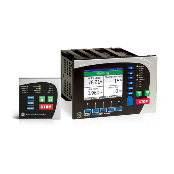
The MM300 is a modular motor protection and control system designed specifically for low-voltage motor applications. It was launched to the market in 2007. The aim of this report is to provide recommendations for the installation of the MM300 relay that may be considered to optimize motor protection reliability. -
Page 4: Reliability
GE Grid Solutions Grid Automation The expansion module is configurable and different modules can be ordered for slots E, F, G and H: Fig. 2 Expansion modules options. 2.2. Reliability The MTBF (Mean Time Between Failures) is 505 years as of April 3, 2019 latest recorded figures. -
Page 5: Warranty
Warranty Fig.3 Ten years warranty logo in the web. GE guaranties all MM300 supplied since October 1st, 2013 for 10 years as the rest of protection and control products that are in active life cycle status. This warranty includes materials and workmanship when the product is wired, set and connected as per the instruction manual and within the published specifications. -
Page 6: Mechanical Recommendations
GE Grid Solutions Grid Automation 3. MECHANICAL RECOMMENDATIONS In order to ensure good connection of the boards, please follow recommendations below: 1- Cable harnesses must not be too tight. Fig. 4 Example of a proper wiring. This allows good connection between the boards and the internal bus board of the relay. - Page 7 GE Grid Solutions Grid Automation It also avoids damaged connectors as per the pictures below: Fig. 5 Example of broken connector. And avoids sagged pins in the boards: Fig. 6 Example of sagged pin. Page 7 of 15 Avda. Pinoa, 10...
- Page 8 GE Grid Solutions Grid Automation Cards screw properly inserted. Fig. 7 Screws properly inserted. Page 8 of 15 Avda. Pinoa, 10 48170 Zamudio SPAIN T +34 94 485 88 00...
- Page 9 GE Grid Solutions Grid Automation 2- Do not use big, flat head nor electric screwdrivers. Use only small manual Philips screwdriver. Fig. 8 Use only small manual Philips screwdriver. This is an example of a relay case damaged due to excessive screw tightening.
- Page 10 Therefore, manual small Philips screwdriver is recommended. Fig. 10 Maximum tightening torque specified in the instruction manual. 3- The MM300 motor Protection series has been designed to be installed in compact drawers in harsh industrial environments. Page 10 of 15 Avda.
- Page 11 GE Grid Solutions Grid Automation In general, the relay may be installed in the front of the panel, assembled together with the graphical control panel (GCP) and a short 2 inches RJ45 cable that connects the main unit with the display.
- Page 12 GE Grid Solutions Grid Automation 4- Ensure that the expansion module tabs have not been damaged. Fig. 13 Expansion module tabs damaged. Page 12 of 15 Avda. Pinoa, 10 48170 Zamudio SPAIN T +34 94 485 88 00...
-
Page 13: Thermal Recommendations
Grid Automation 4. THERMAL RECOMMENDATIONS Temperature may affect all electronics in general, so that in the MM300 we have taken special precaution in the design stage in the following aspects: a. Microcontrollers and memories thermal rating is among the maximum available in the market, frequently automotive range. - Page 14 GE Grid Solutions Grid Automation Fig. 15 Do not install self-adhesive tape covering case slots. 2- Try to install the relay at the bottom of the relay as it is the cooler part. Please find below a picture of the temperature of the drawer taken with an infrared camera: Fig.
- Page 15 6- There are 3 mechanism for heat dissipation: a. Conduction. In the case of MM300 is limited as the base unit housing is made of plastic. b. Convection. This is the most relevant mechanism for MM300 thanks to its slots in the housing.
- Page 16 GE Grid Solutions Grid Automation Fig. 18 Example of forced ventilation inside the drawer. Fig. 19 Best practice fans in each panel (10 drawers/panel). Page 16 of 15 Avda. Pinoa, 10 48170 Zamudio SPAIN T +34 94 485 88 00...
- Page 17 8- The maximum temperature of the CPU should not exceed 90ºC. In the CPU module there is a temperature sensor that provides information of the internal temperature of the relay. This information can be checked using factory password by GE authorized. employees. Fig. 21 Example of CPU maximun temperature measurement.
-
Page 18: Electrical Recommendations
If direct connection is done between the relay and the display, 1.5ft (0.5m), 3ft (1m) or 6.6ft (2m) cables can be used. Fig. 22 Direct connection. ii. If Control Panel Switch (CPS) is used between the displays and the MM300 relay, both cables in total cannot exceed 6.6ft (2m). Fig.23 Connection of the CPS. - Page 19 J2 cable plus J3 cable < 6.6ft (2m) b. Cables used must be GE supplied ones. 5V are supplied from the relay and nearest to these 5V need to arrive to the display. GE Cables have been selected with the minimum resistance to allow these distances.
- Page 20 2- Minimum length cable should be use. Do not use long cables inside small drawers as it can lead in excessive electromagnetic noise coupling. Fig. 24 Do not install longer cables that the ones needed. GE cables are 1.5ft (0.5m), 3ft (1m) or 6.6ft (2m). 3ft (1m) and 6.6ft (2m) cables can be ordered in the online store: https://store.gegridsolutions.com/ProdCategory.aspx?PID=1354&TYPE=ACCESSORY Fig.
- Page 21 GE Grid Solutions Grid Automation Fig. 26 1.5ft cable. Page 21 of 15 Avda. Pinoa, 10 48170 Zamudio SPAIN T +34 94 485 88 00...