Table of Contents

Related Manuals for GE Druck ADTS 505


Summary of Contents for GE Druck ADTS 505
- Page 1 To buy, sell, rent or trade-in this product please click on the link below: http://www.avionteq.com/Barfield-DPS-450-Pitot-Static-Test-Set.aspx Measurement & Control www.avionteq.com Druck ADTS 505 Air Data Test Set User Manual K0260...
- Page 2 © 2013 General Electric Company. All Rights Reserved. Specifications are subject to change without notice. GE is a registered trademark of General Electric Company. Other company or product names mentioned in this document may be trademarks or registered trademarks of their respective companies, which are not affiliated with GE.
-
Page 3: Introduction
Introduction This technical manual provides operating instructions for the Air Data Test System compatible with the requirements of first line operation for the technician and supervisor. Scope This technical manual contains a brief description, operation and testing procedures for the ... -
Page 4: Approved Service Agents
Do not dispose of this product as household waste. Use an approved organisation that collects and/or recycles waste electrical and electronic equipment. For more information, contact one of these: • our customer service department (contact us at www.ge-mcs.com) • your local government office Approved Service Agents For a list of approved service agents, visit our website: www.ge-mcs.com... -
Page 5: Table Of Contents
CONTENTS Table of Contents Preliminary pages Introduction ......................................... i Scope ......................................... i Associated Publication ....................................ii Approved Service Agents . - Page 6 Druck ADTS 505 User Manual Table of Contents (contd) Section Title page Manual Venting of the Aircraft Pitot and Static Systems ................3-24 ADTS 505 Options ................................3-24 3.10 Set-up Reference ................................3-25 MAINTENANCE Introduction ..
- Page 7 CONTENTS Table of Contents (contd) Section Title page [Units] ....................................6-12 [Limits] ....................................6-13 [Alt. Corr.] ..................................... 6-15 [Date Format] .
- Page 8 Druck ADTS 505 User Manual Table of Illustrations Figure Title page ADTS 505 General View .............................. 1-2 ADTS 505 Accessories ..............................2-4 ADTS 505 Altitude Correction On-aircraft ......................2-9 ADTS 505 Altitude Correction Off-aircraft .
-
Page 9: Abbreviations
Abbreviations Abbreviations The following abbreviations are used in this manual; the abbreviations are the same in the singular and plural. Ampere Absolute a.c. Alternating current ADTS Air Data Test Set Altitude ARINC Air Radio Incorporated Airspeed indicator Calibrated airspeed COSHH Control of Substances Hazardous to Health Regulations Centimetre d.c. - Page 10 Druck ADTS 505 User Manual Abbreviations (contd) Return Goods Authorization (Druck procedure) Relative humidity Root mean square Rate of climb Rate Standard serviceability test Volts Positive Negative °C Degrees Celsius °F Degrees Fahrenheit K0260 Issue No. 8...
-
Page 11: Glossary
Glossary Glossary Terminology The terminology used in this manual is specific and individual interpretation must not be introduced. The terms are defined as follows: Adjust To bring to a more satisfactory state; to manipulate controls, levers, linkages, etc. to return equipment from an out-of-tolerance condition to an in-tolerance condition. - Page 12 Druck ADTS 505 User Manual Remove: To perform operations necessary to take an equipment unit out of the next larger assembly or system. To take off or eliminate. To take or move away. Repair: To restore damaged, worn out or malfunctioning equipment to a serviceable, usable or operable condition.
- Page 13 Table of pressure units and conversion factors t i n ) s l t i n ) s l t f / f c / f t f / l t f / f / f n Unit Conversion To convert FROM pressure VALUE 1 in pressure UNITS 1 TO pressure VALUE 2 in pressure UNITS 2, calculate as follows: VALUE 2 VALUE 1...
- Page 14 Druck ADTS 505 User Manual K0260 Issue No. 8...
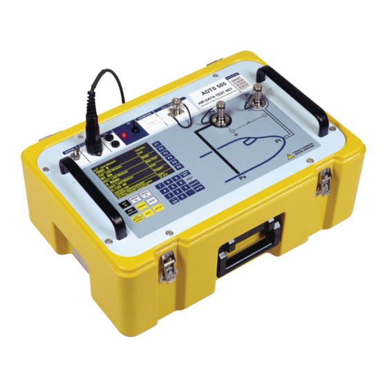
- Page 15 Description 1 - 1 INTRODUCTION Introduction The ADTS 505 is a self-contained flight-line air data test system, enclosed in an ABS case. The unit provides complete pressure and vacuum measuring and control for on-aircraft sense and leak testing, functional tests of air data instruments, components and systems. The ADTS 505 displays and operates in either units of pressure measurement or aeronautical ...
-
Page 16: Adts 505 General View
1 - 2 Druck ADTS 505 User Manual Option A Hand Terminal Option B Hand Terminal 1-1 ADTS 505 G IGURE ENERAL VIEW K0260 Issue No. 8... -
Page 17: Description
Description 1 - 3 Operating Limits The ADTS 505 is supplied with the following pre-defined operating limits. Civil Limits Parameter Limit MIN ALT -1,000 ft MAX ALT 50,000 ft MIN CAS 0.0 knots MAX CAS 450.0 knots MAX MACH 1.000 Mach MAX ROC 6,000 ft/min ARINC LIMITS... - Page 18 1 - 4 Druck ADTS 505 User Manual Max Limits Parameter Limit MIN ALT -2,000 ft MAX ALT 60,000 ft MIN CAS 0.0 knots MAX CAS 650.0 knots MAX MACH 2.800 Mach MAX ROC 40,000 ft/min ARINC LIMITS ALT CORRECTION...
-
Page 19: Installation
Druck ADTS 505 User Manual 2 - 1 INSTALLATION Packaging On receipt of the ADTS 505 check the contents of the packaging against the following lists: ADTS 505 Air Data Test Set Power supply cable - 5 m, no line plug (regional line plugs require option C) - Page 20 2 - 2 Installation Procedure The unit should be at zero/ambient pressure. Disconnect the hose assemblies and stow in the lid. • Switch OFF and disconnect from the electrical power supply. Disconnect the power supply cable and the hand terminal cable. Disconnect the hand terminal cable from the hand terminal.
-
Page 21: Return Goods Procedure
Druck ADTS 505 User Manual 2 - 3 Returned Goods Procedure Should the unit require calibration or become unserviceable it can be returned to the Druck Service Department. Please contact our Service Department, either by 'phone, fax or E-mail, to obtain a Returned... -
Page 22: Adts 505 Accessories
2 - 4 Installation 19 8 19 1- Note: Item 13 supplied for the country of use 2-1 ADTS 505 A IGURE CCESSORIES K0260 Issue No. 8... - Page 23 Druck ADTS 505 User Manual 2 - 5 Qty per Part Number Description assy Kit, fuse/o-ring comprising: AS505-18-3124M0 o-ring AN4 fuse, T5.0A/250V HBC comprising: Hose, red, ST/OPN, AN4, 3m AS505-53-3124M0 Hose, blue, ST/OPN, AN4, 3m AS505-40-3124M0 Cable, AC Power, 5M (open end)
-
Page 24: Electrical Connection
The unit must be connected to the correct electrical power supply as stated, adjacent to the power connector. Open end cables Only a qualified technician (see page i) must fit a connector to a cable supplied by GE (see Table 2-1, item 3). AUTIONS... -
Page 25: Pneumatic Pressure Connection
Druck ADTS 505 User Manual 2 - 7 Connection • The ADTS 505 provides a power supply to the advanced hand terminal when connected to the hand terminal connector on the front panel. • The power supplies must be isolated when connecting the advanced hand terminal in the hazardous area. -
Page 26: Positioning Of The Adts 505
2 - 8 Installation Positioning of the ADTS 505 WARNING: IN AN ENCLOSED AREA WITH FUEL VAPOUR PRESENT THIS EQUIPMENT MUST BE PLACED AT LEAST 0.5 METRES ABOVE FLOOR LEVEL. THIS EQUIPMENT CONTAINS A D.C. MOTOR WITH BRUSHES THAT COULD CAUSE A SPARK. AUTION O OPERATE PLACE THE UNIT ON A HORIZONTAL SURFACE... - Page 27 Druck ADTS 505 User Manual 2 - 9 2-2 ADTS 505 A IGURE LTITUDE ORRECTION AIRCRAFT 2-3 A IGURE LTITUDE ORRECTION AIRCRAFT K0260 Issue No. 8...
- Page 28 2 - 10 Installation K0260 Issue No. 8...
-
Page 29: Operation
Druck ADTS 505 User Manual 3 - 1 OPERATION Preparation WARNING: OBSERVE SAFETY PRECAUTIONS STATED IN LOCAL ORDERS AND THE AIRCRAFT OR EQUIPMENT SERVICING PROCEDURES. Make sure the electrical and pneumatic connectors, electrical cables and pipes and positioning of ... -
Page 30: Display Functions And Units Of Measure
3 - 2 Operation Display Functions and Units of Measure When operating in either pressure measuring or pressure controlling modes, the ADTS 505 can display the following information: Aeronautical Functions Display Abbreviation Displayed Units (if applicable) Altitude ft, m Calibrated Airspeed kts, km/h, mph Mach MACH... -
Page 31: Quick Reference
Druck ADTS 505 User Manual 3 - 3 Quick Reference the display shows the main pressure display (Leak Measure or Control mode) with KEY-PAD FUNCTION normal operation key functions. Key/selection Function and comments F1-F6 Function keys for menus ALT/Ps Altitude (Aeronautical units) or Ps (pressure units) -
Page 32: First Time Operators
3 - 4 Operation First Time Operators The following sequences of operation should be used by first time operators and by operators that use the equipment occasionally. For regular users, familiar with the equipment, go to section 3.5. Set the power supply switch to ON and the power-on routine starts. The display first shows: After approximately five seconds the display shows SYSTEM STARTING... - Page 33 Druck ADTS 505 User Manual 3 - 5 The system is now ready for use. OTES The ADTS 505 is a continuous, self-monitoring system. If the system detects an error, the display shows an error message. Lists of errors are detailed in Section 5, Fault Finding and Testing.
-
Page 34: Operating Modes
3 - 6 Operation 3.4.1 Operating Modes The air data test system can now be set for a variety of functions and modes. In the following, examples of measure mode, control mode, leak measure mode and go-to-ground show the key presses and selections required for each mode. - Page 35 Druck ADTS 505 User Manual 3 - 7 Checking the Limits Before use on aircraft systems or components check that the limits are within the values stated in the appropriate maintenance manual. There are sets of factory-defined limits: Civil, Standard, Max or EPR (refer to Section 1 for details) At each power-up sequence the default set of limits "CIVIL"...
- Page 36 3 - 8 Operation Control Mode When the system is in measure mode, to enter control mode press: The display changes to: Note: The number of parameters displayed depends on the settings made in set-up, see previous page. New set-point To change the Aim value, press the required parameter key and, using the numeric keys, set the new Aim value.
- Page 37 Druck ADTS 505 User Manual 3 - 9 Go to GROUND When the system is in control mode press: Note: Go to ground does not operate in measure mode. The ALT Aim value immediately changes to the current ground pressure (local airfield altitude) and the system safely controls to the GROUND value stored from power-up.
-
Page 38: Operation And Example Procedures
3 - 10 Operation Operation and Example Procedures 3.5.1 Operating Procedures The procedures show the steps required to make sure the ADTS 505 is serviceable and the settings required to test an aircraft system or component. For further information refer to the Section 6 - Reference and Specification. -
Page 39: Control Or Measure Parameter
Druck ADTS 505 User Manual 3 - 11 3.5.3 Control or Measure Parameter To change the displayed Measure parameters: Press SETUP [Displays], [Single, Dual, Quad], press CLEAR/QUIT repeatedly until the display goes to Leak Measure Mode. Measure parameters: ... - Page 40 3 - 12 Operation Press LEAK MEASURE/CONTROL to select Control mode. Using the set-up menu, choose the limits set for the aircraft or UUT, see 3.5.6. Press CLEAR/QUIT repeatedly until the display shows control mode. Set ROC/RtPs to 5000ft/min, enter an altitude aim of 1000 ft and an airspeed of 200 knots. ...
-
Page 41: Changing The Units Of Measurement
Druck ADTS 505 User Manual 3 - 13 3.5.5 Changing the Units of Measurement The units of measurement can be changed Main Menu to units of pressure measurement or aeronautical units. Units To change the units: Units •... - Page 42 3 - 14 Operation To select a limit set (User) Press SETUP, the display shows Setup, [Limits] User Supervisor [xxxxxx], where xxxxxx is the current name of Limits the selected limit set. Select [Limits] [xxxx] F3. Limits Active Limit Set: CIVIL Available Preset Limits The display highlights the current set of limits ...
-
Page 43: Tests Before Use
Druck ADTS 505 User Manual 3 - 15 Tests Before Use Note: It is recommended that the following test is carried out, before use, at least once per day. Switch the unit ON. After the power-up routine, fit the blanking caps to the outlet ports. -
Page 44: Testing The Aircraft Static System
3 - 16 Operation 3.7.1 Testing the Aircraft Static System CAUTIONS: BSERVE ALL SAFETY PRECAUTIONS DETAILED IN THE IRCRAFT AINTENANCE ANUAL HEN USING STATIC ONLY MAKE SURE THAT THE DIFFERENTIAL PRESSURE STAYS WITHIN ASI. THE LIMITS OF THE Remove the static blanking cap and switch ON. Connect the ADTS 505 to the Aircraft Static System. -
Page 45: Testing The Aircraft Pitot System
Druck ADTS 505 User Manual 3 - 17 3.7.2 Testing the Aircraft Pitot System CAUTIONS: BSERVE ALL SAFETY PRECAUTIONS DETAILED IN THE IRCRAFT AINTENANCE ANUAL HEN USING PITOT ONLY MAKE SURE THAT THE DIFFERENTIAL PRESSURE STAYS WITHIN THE ASI. LIMITS OF THE Remove the Pitot and static blanking caps and switch ON. -
Page 46: Combined Testing Of The Aircraft Pitot And Static Systems
3 - 18 Operation Combined Testing of the Aircraft Pitot and Static Systems 3.7.3 CAUTION: BSERVE ALL SAFETY PRECAUTIONS DETAILED IN THE IRCRAFT AINTENANCE ANUAL It is possible to combine the tests detailed in paragraphs 3.7.1 and 3.7.2. Any combination of altitude and airspeed can be established within the programmed set limits. -
Page 47: Mach Test And Constant Mach
Druck ADTS 505 User Manual 3 - 19 3.7.4 Mach Test and Constant Mach Example To go to 0.45 Mach, proceed as follows: • Press LEAK MEASURE/CONTROL to enter Control Mode. • Press SPEED/Qc then RATE to display rate of change of airspeed. -
Page 48: Leak Testing
3 - 20 Operation 3.7.5 Leak Testing General Apply pressure to the system under test as detailed in Testing the Aircraft Static or Pitot system. Before starting the leak test, check that the ADTS 505 is operating within range of the set limits. Example To leak test a pitot system to 300 knots at a maximum rate of 300 knots/min and a static system to 30,000 ft at a maximum rate 5,000 ft/min. -
Page 49: Airspeed Switch Test
Druck ADTS 505 User Manual 3 - 21 3.7.6 Airspeed Switch Test The following example shows how an airspeed switch can be functionally checked. Note: For low airspeed switches (i.e. 130 knots) Pitot only could be used, 3.7.2. •... -
Page 50: Engine Pressure Ratio (Epr)
3 - 22 Operation 3.7.7 Engine Pressure Ratio The ADTS 505 may be used to check EPR sensors and indicators. Use Ps (static) for INLET pressure and Pt (Pitot) for OUTLET pressure. To carry out an EPR check, the display must be showing units of pressure measurement e.g., mbar, ... -
Page 51: Go To Ground
Druck ADTS 505 User Manual 3 - 23 3.7.8 Go To Ground On completion of testing and, before disconnecting from the aircraft system or UUT, the pressures in the system must be taken to the local atmospheric pressure (ground) with zero airspeed. -
Page 52: Manual Venting Of The Aircraft Pitot And Static Systems
See 6.4 for the details and procedures for the advanced hand terminal. If the ADTS 505 unit is not at the correct modification state, contact the local GE Sensing sales team ... -
Page 53: Set-Up Reference
Druck ADTS 505 User Manual 3 - 25 3.10 Set-up Reference The following charts provide a user reference for the set-up functions of the ADTS 505. F1 Display Display F1 Single F2 Dual F3 Quad F4 Save Settings [Monitor] F6 Handset... - Page 54 3 - 26 Operation K0260 Issue No. 8...
- Page 55 Druck ADTS 505 User Manual 3 - 27 K0260 Issue No. 8...
- Page 56 3 - 28 Operation K0260 Issue No. 8...
- Page 57 Druck ADTS 505 User Manual 4 - 1 MAINTENANCE Introduction This section details the maintenance tasks to be carried out by the operator. The maintenance chart shows the maintenance tasks, the periodicity of each task and a code referenced to the task detailed in 4.3.
-
Page 58: Maintenance
Note: Equivalent substitutes can be used. 4-2 M ABLE ATERIALS Manufacturer’s Ref Code Nomenclature part number Voltmeter, Digital GE DPI620 Insulation Tester, 250V Robin Note: Equivalent substitutes can be used. 4-3 T ABLE OOL AND QUIPMENT EQUIREMENTS K0260 Issue No. 8... -
Page 59: Maintenance Tasks
Druck ADTS 505 User Manual 4 - 3 Maintenance Tasks Check that all the equipment is present; record any deficiencies. Visually inspect the external of the ADTS 505, and its associated equipment, for obvious signs of damage, dirt, and the ingress of moisture. -
Page 60: Routine Maintenance
4 - 4 Maintenance Routine Maintenance WARNING: S WITCH OFF AND DISCONNECT THE POWER SUPPLY BEFORE STARTING ANY MAINTENANCE TASK Carrying out the maintenance tasks detailed 4.3. Servicing Procedures The following procedures provide instructions to test and replace items for the operator. Return the unit to the repair depot for further testing and replacement of items. -
Page 61: Fuse Replacement
Druck ADTS 505 User Manual 4 - 5 Fuse Replacement (Fig 4-1) Replace the fuse when detailed in Section 5, Testing and Fault Finding: • Set the power switch to OFF. Note: The power switch is not a power isolator as defined by EN61010. - Page 62 4 - 6 Maintenance Hand Terminal Cable Tests Carry out the following check as detailed in Testing and Fault Finding, Section 5. Measure continuity using the DVM (item 1, Table 4-3) set to an appropriate range. Measure the continuity between corresponding pins at each end of each cable assembly. The measured resistance must not exceed 0.10 É...
-
Page 63: Testing And Fault Finding
Druck ADTS 505 User Manual 5 - 1 TESTING AND FAULT FINDING Introduction The ADTS 505 contains a built-in, self-test and diagnostic system. The system continuously monitors the performance of the unit and at power-up carries out a self-test. Warning and error messages are displayed during normal operation if out of range values are entered or if faults occur. -
Page 64: Standard Serviceability Test
5 - 2 Testing and Fault Finding Standard Serviceability Test The following procedure shows if the unit is serviceable and checks functions and facilities of the ADTS 505. In this procedure: • All key presses are highlighted in BOLD and shown as identified on the front panel. •... -
Page 65: Fault Diagnosis
Druck ADTS 505 User Manual 5 - 3 • Set the display to QUAD format (see 3.4.1 to change) and aeronautical units of ft, kts and ft/min (see 3.5.5 to change). • Press ALT/Ps, ROC/RtPs, SPEED/Pt and RATE to display the required parameters. -
Page 66: Fault Finding Chart
5 - 4 Testing and Fault Finding 5-1 F IGURE AULT INDING HART K0260 Issue No. 8... - Page 67 Druck ADTS 505 User Manual 5 - 5 5-1 F ABLE AULT INDING Fault Symptom Probable cause Action Power supply indicator Faulty power supply outlet. Check power supply. does not light. Unserviceable power supply front Check/replace fuse. panel fuse. Check/replace fuse.
-
Page 68: Further Testing
5 - 6 Testing and Fault Finding Further Testing The following tests should only be carried out if a pneumatic leak or a controller instability is suspected. Test Environment and Preliminary Operations These tests should be carried out in a room with a stable temperature environment within the operating temperature range. -
Page 69: System Screen For Diagnosis
Druck ADTS 505 User Manual 5 - 7 On-screen Assessment (Figure 5-2) This procedure enables real time assessment of the system. Each valve and transducer is characterized to obtain maximum performance. Any values shown on the screen are an indication and not a precise value. -
Page 70: System Screen
5 - 8 Testing and Fault Finding Data Identifier Function Expected Display or Value RPT Diagnostics Ps/Altitude Sensor RPT Diode [mV] Temperature Compensation 400 (hot) ..... 800 (cold) RPT Count Value proportional to pressure 248,553 .....4,473,600 TEMP [c] Ps channel (RPT) measured temperature 5°.. - Page 71 Druck ADTS 505 User Manual 5 - 9 Schematic shown on the advanced hand terminal 5-3 S IGURE YSTEM CHEMATIC K0260 Issue No. 8...
- Page 72 5 - 10 Testing and Fault Finding Key-pad Testing The front panel key-pad and the hand terminal key-pad can be tested using the facility in the maintenance/calibration selection of the set-up menu. The procedure to test the key-pad requires each key to be pressed in turn and to confirm the correct key press on the display.
- Page 73 Druck ADTS 505 User Manual 5 - 11 Pressure leak check This procedure verifies that the unit is leak tight under positive pressure conditions. Press LEAK MEASURE/CONTROL to enter control mode. Enter an ALT/Ps Aim of 1016 mbar. Enter a SPEED/Qc Aim of 272 mbar. Wait for the aim values to be achieved then wait for 1 min.
- Page 74 5 - 12 Testing and Fault Finding Vacuum leak check This procedure verifies that the unit is leak tight under vacuum conditions. Press LEAK MEASURE/CONTROL to enter control mode. Enter an ALT/Ps Aim of 100 mbar. Enter a Speed/Qc Aim of 0 mbar. Wait the required time for temperature stabilization e.g., one minute.
- Page 75 Druck ADTS 505 User Manual 5 - 13 Controller Stability This section verifies the control stability. Press LEAK MEASURE/CONTROL to turn the pressure controllers on. Enter an ALT/Ps Aim of 510 mbar with a rate of change of 204 mbar/min.
-
Page 76: Fault Finding
5 - 14 Testing and Fault Finding Fault Finding System Messages In the event of a malfunction, the built-in, self-test and diagnostic system displays a message and a code. The message heading Error indicates a fault or condition that interrupts normal operation. - Page 77 Druck ADTS 505 User Manual 5 - 15 Message Probable Cause Action Abort key pressed on Wait until system completes abort Abort sequence started by user hand terminal sequence "Cannot Modify Altitude Altitude Correction Change units in setup to aero units Correction in Pressure Units"...
- Page 78 5 - 16 Testing and Fault Finding Message Probable Cause Action Restart system, if fault repeats "Vacuum pump has stalled" Internal mechanical fault -return unit to repair depot "Pressure pump processor has Internal fault Return unit to repair depot failed" "Pressure pump lead is Return unit to repair depot disconnected"...
- Page 79 Druck ADTS 505 User Manual 5 - 17 Additional Messages Internal temperature The temperature sensor in the pressure measurement system measures the temperature of the pressure manifold. At a temperature greater than 60°C the sensor triggers an overheat fault. In measure mode, the display flashes between the normal aim/measure screen and "Ps Sensor Outside Calibrated Range".
- Page 80 5 - 18 Testing and Fault Finding Intentionally left blank K0260 Issue No. 8...
-
Page 81: Reference And Specification
Druck ADTS 505 User Manual 6 - 1 REFERENCE AND SPECIFICATION Introduction This section includes a full description of each key-pad selection and function, the main menu selections and functions and set-up selections and functions. The available keys are: F1 - F6... -
Page 82: Alt/Ps
6 - 2 Reference and Specification ALT Ps • In aeronautical units (ft or m), this key selects an altitude display. • In pressure units (mbar, inHg etc.), this key selects a static pressure (Ps) display. • Select [Units], from the main menu, to change the display units. •... -
Page 83: Roc Ps Rate
Druck ADTS 505 User Manual 6 - 3 MACH Pt • In aeronautical units (ft/kts or m/km/h), this key selects the Mach display. • In pressure units (mbar, inHg etc.), this key selects the total pressure (Pt) display. • If the altitude aim is changed, after the entry of CAS, the Mach aim value changes while the CAS value remains unchanged. -
Page 84: Rate
6 - 4 Reference and Specification RATE • In aeronautical units (kts, km/h), this key shows the rate of change of airspeed (Rate CAS). • In pressure units (mbar, inHg etc.), this key shows the rate of change of pressure (Rate Qc) display. -
Page 85: Leak Measure/Control
Druck ADTS 505 User Manual 6 - 5 LEAK MEASURE/CONTROL • This key switches between Control and Leak Measure mode. • When in leak measure mode, the display shows “LEAK MEASURE”. • Press LEAK MEASURE/CONTROL to switch the controllers on. No significant pressure transients are produced when regaining control. -
Page 86: Clear/Quit
6 - 6 Reference and Specification 0 to 9 • Use these keys for numeric entry. Press ENTER to complete numeric entry. All data entry is based on over-writing the existing value. • If a mistake is made during numeric entry, press DELETE to remove the last entered digit. At any time, the existing value may be recovered by pressing CLEAR/QUIT. -
Page 87: Help
Druck ADTS 505 User Manual 6 - 7 HELP • The HELP key provides information on each key function. The help message generally gives associated functions and ways of changing the use of each key. When the display shows the main pressure display, the user can get help on any of the keys on the key-pad. -
Page 88: Main Menu
6 - 8 Reference and Specification Main Menu In the Leak Measure and Control modes the display shows and provides further selections. [Rate Timer] • The Rate Timer starts an internal timer for a pre-defined set of times. On the completion of the time period, the display shows the average rate of change over the time period. -
Page 89: [Units]
Druck ADTS 505 User Manual 6 - 9 [Units] • The list of units shown in the main menu divide into aeronautical units and units of pressure measurement. The display shows the available units selected from the list in the set-up menu. -
Page 90: [Epr]
6 - 10 Reference and Specification [EPR] • Engine Pressure Ratio only operates in units of pressure measurement (mbar, inHg etc.) with a set of pre-defined limits, see section 1. The ADTS 505 can be used to check EPR sensors, indicators and EPR data for engine control systems. -
Page 91: Setup
Druck ADTS 505 User Manual 6 - 11 6.3 SETUP Set-up allows access to secondary functions that do not have an assigned key and are not part of the main menu. 6.3.1 Set-up 1 of 2 [Display], [Single, Dual, Quad, Hand Term] In leak measure mode, after each parameter, the display shows "Leak Measure". -
Page 92: [Units]
6 - 12 Reference and Specification [Units] • The list of units in the set-up menu divide into aeronautical units and units of pressure measurement. The available units are: Aeronautical units ft and kts (ft/min) (includes Mach) m and km/h (m/min) (includes Mach) m and mph (m/s) (includes Mach) m and km/h (hm/min) (includes Mach) Units of pressure measurement... -
Page 93: [Limits]
Druck ADTS 505 User Manual 6 - 13 [Limits] • The ADTS 505 is preprogrammed with the manufacturer's standard, civil and maximum limit sets (STD, CIVIL and MAX). This facility enables five sets of additional limits to be programmed and allows the selection of a set of limits to be used; each additional set of limits can be identified by its aircraft name or type. -
Page 94: Arinc 565 Limits Graph
6 - 14 Reference and Specification • After manufacture the ADTS 505 only contains the pre-defined limit sets. To create the first user-defined set, use the to step down the list. At the bottom of the list press again, select [Modify Name], F5 and using the seven screens of characters compose the name of the new limit set, press ENTER. -
Page 95: [Alt. Corr.]
Druck ADTS 505 User Manual 6 - 15 [Alt. Corr.] Altitude Correction (Figures 6-2 and 6-3) • This function allows the altitude correction value to be changed. The display shows the altitude correction value in the lower part of the display screen. -
Page 96: [Date Format]
6 - 16 Reference and Specification 6-3 A IGURE LTITUDE CORRECTION OFF AIRCRAFT [Date Format] The format of the date can be changed to satisfy local requirements. K0260 Issue No. 8... -
Page 97: Set-Up 2 Of 2
Druck ADTS 505 User Manual 6 - 17 6.3.2 Set-up 2 of 2 [Operational Hours] • This display shows the total number of hours for system operation and the total number of hours of pump Setup (2 of 2) operation. The system records, as a background task, Setup the total running hours of the unit. -
Page 98: [Auto Leak]
6 - 18 Reference and Specification [View Manifold] ¤ This facility is the same as view manifold (above) but within the PIN protected area. [Valve Calibration] ¤ The system operates the apply and release valves, measures performance, calculates and stores the characteristics of each valve. This takes approximately 20 minutes to complete. -
Page 99: Other Features
Druck ADTS 505 User Manual 6 - 19 Other Features Elapsed Time Counter The system records, as a background task, the total running hours of the unit and the pump running hours. This facility assists with the scheduling of the 1000 hour and 3000 hour servicings. -
Page 100: Hand Terminal Option B
6 - 20 Reference and Specification Normal operation using option A and option B REMOTE Option B Advanced HAND TERMINAL OPERATING Hand Terminal SPEED CLEAR MACH QUIT ABORT GROUND RATE RATE Ps DELETE LEAK MEASURE SETUP HELP ENTER CONTROL Option A Hand Terminal Uploading and downloading operations using the PC communications cable, power pack and power supply cable... -
Page 101: Power-Up Displays
Druck ADTS 505 User Manual 6 - 21 Power-up routine • Set the power supply switch to ON. • Check that the screen shows the correct display for a successful power-up. Check: ¤ the pump operates. ¤ the power indicator lights ¤... - Page 102 6 - 22 Reference and Specification Selected standard function Touch screen keys 6-6 M IGURE CREEN Screen Displayed Key Selections Touch screen key Function and comments UP/DOWN Moves the screen highlight bar up/down. Select Selects the test or set of values highlighted by the up/down function. Back Returns to the previous screen.
-
Page 103: Main Menu Structure
Druck ADTS 505 User Manual 6 - 23 Select Customer Test Sequence System Set-up File Screen Manual Control Screen Engine Pressure Ratio Screen 6-7 M IGURE TRUCTURE K0260 Issue No. 8... -
Page 104: Manual Control Selections
6 - 24 Reference and Specification Manual Mode 6-8 M IGURE ANUAL CONTROL SELECTIONS Selecting Control and Leak/Measure Modes Manual test control always starts in leak measure mode displaying pressures in the last selected units of measurement. The system can be switched between aero units and pressure units, these units can only be changed in set-up mode. - Page 105 Druck ADTS 505 User Manual 6 - 25 Alt and CAS readings/results Wait time Measure time XAMPLE IMER CREEN Rate Timer Selected in Leak/Measure Mode Use the touch screen keys to select wait and measure times and use the numeric keys to enter the values.
- Page 106 6 - 26 Reference and Specification Ground Selected in Control Mode Use the GROUND touch screen key to select go-to-ground. The displayed channel aims show GROUND, the controller takes all channels to ground pressures and Qc to zero as shown above. Note: At any time during this operation, pressing Leak/Measure stops the operation.
-
Page 107: Set-Up Menu Selections
Druck ADTS 505 User Manual 6 - 27 Select Set-up From the main menu, select system set-up. see page 29 see page 38 see page 28 6-9 S IGURE UP MENU SELECTIONS K0260 Issue No. 8... - Page 108 6 - 28 Reference and Specification Use the Up and Down keys to highlight the required aeronautical and pressure units. Press SAVE SETTINGS to store in non-volatile memory or press MAIN MENU to store in volatile memory and return to the Main Menu Screen. Press RESTORE DEFAULTS to restore the last set of stored values and unit selection saved as a default.
- Page 109 Druck ADTS 505 User Manual 6 - 29 Altitude Correction An altitude correction must be made to allow for the difference in height between the reference level of the ADTS 505 and the reference level of the aircraft’s altitude sensors. Select the Instrument Altitude Correction and, using the numeric keys, enter the correction value (see Fig 2-2).
- Page 110 6 - 30 Reference and Specification Title Measure/ Control Actual channel readings Actual rate of pressure Set of aim Test values to be procedure used in control step mode Only available in Control Mode changes to Rate Timer in Leak/Measure Mode Rate aim to be used in this TP step.
-
Page 111: Test Sequence Selections
Druck ADTS 505 User Manual 6 - 31 Creating Custom Test Sequences for the ADTS 505 Instructions for generating or editing source data for test table values The data shown on each screen or table of the test sequence comes from a single data source file. This .CSV format file uses numeric data fields separated by commas. - Page 112 6 - 32 Reference and Specification K0260 Issue No. 8...
- Page 113 Druck ADTS 505 User Manual 6 - 33 Example Test Table Parameter Label Prompt Message Test Identifier Begin Test Table <TEST TABLE TITLE 1> <HEADER 2> <HEADER 1> REF (a) <TEST DESCRIPTOR (a)> <MESSAGE (a)> REF (b) <TEST DESCRIPTOR (b)>...
- Page 114 6 - 34 Reference and Specification File Transfer Flowchart File transfer Create XLS file from test data save as CSV file Connect hand terminal see figure 6-4 After power-up of the hand terminal press EXIT PROGRAM The hand terminal display shows: Windows®...
- Page 115 Druck ADTS 505 User Manual 6 - 35 Transferring <NEW AIRCRAFT.CSV>files from a PC to: the ADTS 505 Advanced Hand Terminal or ADTS 505 New .csv file test scripts can be tested for general syntax and screen formatting using the desktop PC utility “ADTS 505 Remote”...
- Page 116 6 - 36 Reference and Specification To copy a new script file (.csv file) to the Advanced Hand Terminal click-on and highlight the required file and, using the File/Copy/Paste facility in Windows®, click on the Hand terminal/Hard Disk directory as the destination of the file.
- Page 117 Druck ADTS 505 User Manual 6 - 37 DK286 – Touch Screen Calibrator This program enables the calibration of the touch screen. To execute this application, exit from the ADTS 505 program and double click on the Calibrate Touch icon .
-
Page 118: System Status
6 - 38 Reference and Specification valves valves valves valves open closed open closed Leak Measure Mode Control Mode valves valves open open At ground 6-12 S IGURE YSTEM TATUS K0260 Issue No. 8... -
Page 119: Example Error Screen
Druck ADTS 505 User Manual 6 - 39 Ps aim value unobtainable Ps aim value unobtainable 6-13 E IGURE XAMPLE RROR CREEN K0260 Issue No. 8... -
Page 120: Option B Advanced Hand Terminal Specification
6 - 40 Reference and Specification Option B Advanced Hand Terminal Specification Physical Size 212 x 178 x 63 mm (8.35” x 7” x 2.48”) Weight 2.0 kg [4.4 lb.] Conformity BSEN61010, BSEN61326-1, 97/23/EC BS EN 61326 (Class A) Electrical safety BSEN61010 Pressure safety Pressure Equipment Directive - class: sound engineering practice (SEP) -
Page 121: Specification
Druck ADTS 505 User Manual 6 - 41 Specification Physical Specification Size 265 mm x 520 mm x 355 mm (10.4” x 20.5" x 14") Weight 15 kg [33 lb] Conformity EN 61326 (refer to the declaration of conformity for details) - Page 122 6 - 42 Reference and Specification Measurement and Control Range Specifications Operating Range and Performance Limits are set pre-defined tabular limits known as ARINC 565, CIVIL and EPR these can be selected through the SETUP menu. Operators may also configure the display to aeronautical or pressure units but should be aware that when units of pressure are selected, wider full-scale pressure limits will be enabled for some parameters.
- Page 123 Druck ADTS 505 User Manual 6 - 43 Performance expressed in pressure units Altitude Sensor Airspeed Sensor (Ps) (Qc) mbar abs inHg diff Units inHg abs mbar diff 1 to 73.53 71.7 to 1355 2.1 to 40 -950 to +2490 0.1 to 10...
- Page 124 6 - 44 Reference and Specification Intentionally left blank K0260 Issue No. 8...