Makita DDF481 Technical Information
Hide thumbs
Also See for DDF481:
- Instruction manual (68 pages) ,
- Instruction manual (53 pages) ,
- Instruction manual (53 pages)
Table of Contents
Advertisement
Quick Links
T
ECHNICAL INFORMATION
Model No.
Description
C
ONCEPT AND MAIN APPLICATIONS
Model DDF481 is a supreme class cordless driver drill
powered by 18V Li-ion battery of BL1815N (1.5Ah)/ BL1820 (2.0Ah)/
BL1830 (3.0Ah)/ BL1840 (4.0Ah)/ BL1850 (5.0Ah) .
Its main features are:
• Max lock torque: 125N.m. (1,090in.lbs)
• Compact tool size with an overall length of 205mm (8-1/8")
• Efficient Brushless DC motor provides higher power and productivity
than that of 18V Cordless driver drill model BDF458/DDF458.
Note: BL1815 is not compatible.
S
pecification
Voltage: V
Capacity: Ah
Battery
Energy capacity: Wh
Cell
Charging time (approx.): min.
Max output: W
No load speed: min.
¹= rpm
ˉ
Capacity of drill chuck: mm (")
Capacity: mm (")
Torque setting
Clutch torque setting: N.m (in.lbs)
Max lock torque: N.m (in.lbs)
Max fastening torque:
N.m (in.lbs)
Electric brake
Mechanical speed control
Variable speed control
Reversing switch
LED job light
Weight according to
EPTA-Procedure 01/2003*
*
3
: with Grip assembly
S
tandard equipment
4
Battery*
Charger*
4
Battery cover*
5
+ – bit 2-45
Belt clip
(+) Screw M4x12
Grip assembly
Bit holder
Plastic carrying case
*4: Battery and charger are not supplied with "Z" model
*5: Supplied with the same quantity of extra Battery
Note: The standard equipment may vary by country
or model variation.
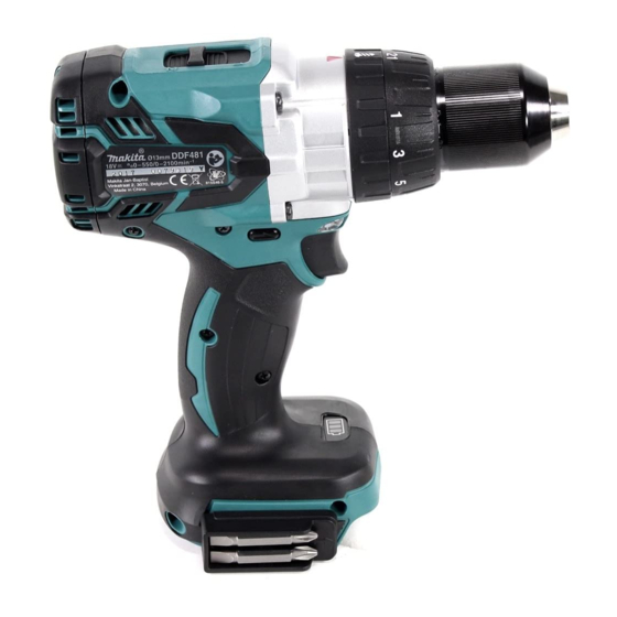
DDF481
18V Cordless driver drill
High
Low
Steel
Wood
Soft joint
Hard joint
3
: kg (lbs)
18
1.5, 2.0, 3.0, 4.0, 5.0
27, 36, 54, 72, 90
Li-ion
15, 24, 22, 36, 45 with DC18RC
640
0 - 2,100
0 - 550
1.5 (1/16) - 13 (1/2)
13 (1/2)
76 (3)
21 stage + drill mode
1.0 - 10.0 (9 - 89)
125 (1,090)
60 (530)
115 (1,020)
Yes
Yes (2 speed)
Yes
Yes
Yes
1
2.4 (5.2)*
2
2.6 (5.8)*
O
ptional accessories
Fast charger DC18RC
Charger DC18SD
Charger DC24SC
Automotive charger DC18SE
Quad Port Charger DC18SF
Battery BL1815N
Battery BL1820
Battery BL1830
Battery BL1840
Battery BL1850
OFFICIAL USE
for ASC & Sales Shop
PRODUCT
P 1/ 11
L
H
W
Dimensions: mm (")
Length (L)
205 (8-1/8)
Width (W)
79 (3-1/8)
249 (9-3/4)*
Height (H)
266 (10-1/2)*
*1:
with BL1815N or BL1820
*2:
with BL1830, BL1840 or BL1850
Drill bits for wood
Drill bits for steel
Driver bits
Belt clip
Bit holder
1
2
Advertisement
Table of Contents

Related Manuals for Makita DDF481


Summary of Contents for Makita DDF481
- Page 1 DDF481 Description 18V Cordless driver drill ONCEPT AND MAIN APPLICATIONS Model DDF481 is a supreme class cordless driver drill powered by 18V Li-ion battery of BL1815N (1.5Ah)/ BL1820 (2.0Ah)/ BL1830 (3.0Ah)/ BL1840 (4.0Ah)/ BL1850 (5.0Ah) . Its main features are: Dimensions: mm (")
-
Page 2: Necessary Repairing Tools
P 2/ 11 epair CAUTION: Repair the machine in accordance with “Instruction manual” or “Safety instructions”. [1] NECESSARY REPAIRING TOOLS Code No. Description Use for 1R264 Torque wrench removing Drill chuck 1R291 Retaining ring S and R pliers removing Retaining ring (INT) R-15 1R298 Hex bar 10 with square socket removing Drill chuck removing Drill chuck (If it is impossible to remove Drill chuck by the steps 1R359 Chuck removing tool... - Page 3 (9) Turn 1R264 counterclockwise to remove Drill chuck. (Fig. 8) side Note: When it is impossible to remove Drill chuck, try the steps wide side with 1R359 mentioned in Makita repair tool list. Fig. 6 Fig. 8 Keep 1R404-B parallel M5x10 with 1R404-A.
- Page 4 P 4/ 11 epair Fig. 13 [3] DISASSEMBLY/ASSEMBLY [3] -2. Gear assembly, Rotor, Stator assembly, Speed change lever assembly (cont.) Caution for Handling of Rotor When handling or storing multiple Rotors, be sure to keep a proper distance between Rotors as shown in Fig. 13 Fig.
- Page 5 P 5/ 11 epair [3] DISASSEMBLY/ASSEMBLY [3] -2. Gear assembly, Rotor, Stator assembly, Speed change lever assembly (cont.) (4) Assemble Motor section with Gear assembly and Speed change lever assembly to Housing L at a time. And assemble Switch and F/R change lever to Housing L. (Fig. 18) Then, assemble Housing R to Housing L. (5) Assemble Rear cover to Housing set.
-
Page 6: Grip Assembly
Note: Grip assembly for DHP481 has M5x10 Thumb screw and M5 Hex nut, and therefore, the grip is different from that of DDF481. Loosening the thumb screw will cause the M5 Hex nut to be removed from Arm L. M5x10... -
Page 7: Circuit Diagram
P 7/ 11 ircuit diagram Fig. D-1 Color index of lead wires' sheath Purple Black Yellow White Orange Brown Blue Gray Stator complete Switch LED circuit Controller Red lead wire is used for some country instead of white. Terminal... -
Page 8: Wiring Diagram
P 8/ 11 iring diagram Fig. D-2 View before setting Switch and F/ R change lever in place Rib A Place Connector this space among Rib A, Rib B and Boss. Stator A’ LED circuit Thick lead wires from Stator must be put on the other thin See the following illustration lead wires. - Page 9 P 9/ 11 iring diagram Fig. D-3 Switch Lead wire (white) Flag terminal Set Flag terminal to Switch as shown above. Stator complete Thick lead wires from Stator complete must be put on the other thin lead wires for the designated area . Boss A Rib C Lead wires from Stator complete must be...
-
Page 10: Check List For Trouble Shooting
P 10/ 11 rouble shooting Whenever you find any trouble in your machine, first, refer to this list to check the machine for solution. Note in Repairing Fig. D-4 (1) Use the full charged battery which has the star mark. (Fig. D-4) (2) When Housing is disassembled, check the conditions of the electrical parts Star mark (Connectors, Lead wires, Switches, etc.), Armature, Stator, Gear section, etc. - Page 11 P 11/ 11 rouble shooting Test for recognizing the trouble on FET (Field effect transistor) in Controller (1) Set Digital tester (1R402) in the diode mode ( mark on the tester: Refer to Fig. D-5.) (2) Switch, Terminal, Controller and Stator are connected each other as drawn in Fig. D-6. Do the following steps.