Advertisement
Quick Links
T
ECHNICAL INFORMATION
Model No.
Description
C
ONCEPT AND MAIN APPLICATIONS
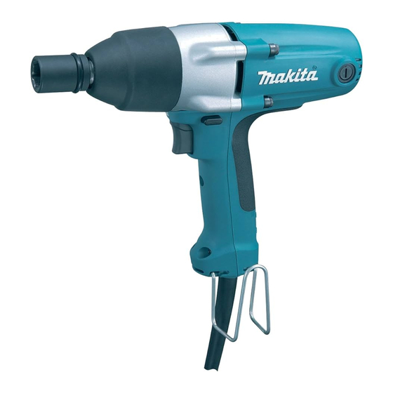
TW0250 has been developed as a sister model of TW0200,
featuring 500W powerful motor to deliver maximum fastening
torque of 250N.m (25% higher than TW0200's 200N.m)
for a wide range of professional applications.
S
pecification
Voltage (V)
110
No load speed: min.-
Impacts per min.: min.-
Driving shank
Standard bolt
Capacities
High tensile bolt
Max. fastening torque*: N.m (ft.lbs)
Rotation reversing facility
Power supply cord: m (ft)
Protection against electric shock
Net weight : kg (lbs)
*torque at 3 seconds after seating when fastening M16 high tensile bolt
S
tandard equipment
Socket 24-25 .................................. 1
Hook .............................................. 1
Plastic carrying case ...................... 1
Note: The standard equipment for the tool shown above may differ by country.
O
ptional accessories
Sockets
Extension bar
Universal joint
Oval socket
Bit adapter
Socket bit
Phillips bits
TW0250
Impact Wrench
Current (A)
Cycle (Hz)
4.8
50/60
=rpm
1
=ipm
1
Continuous Rating (W)
Input
500
0 - 2,300
0 - 2,300
12.7mm (1/2") Square
M10 - M20
M10 - M14
250 (190)
Yes
(by push-button type switch)
2.5 (8.2)
Double insulation
2.1 (4.6)
PRODUCT
P 1/ 10
L
W
Dimensions: mm (")
Length (L)
250 (9-7/8)
Width (W)
72 (2-13/16)
Height (H)
220 (8-5/8)
Max. Output (W)
Output
250
365
H
Advertisement

Related Manuals for Makita tw0250


Summary of Contents for Makita tw0250
- Page 1 Description Impact Wrench ONCEPT AND MAIN APPLICATIONS TW0250 has been developed as a sister model of TW0200, featuring 500W powerful motor to deliver maximum fastening torque of 250N.m (25% higher than TW0200’s 200N.m) for a wide range of professional applications.
-
Page 2: Necessary Repairing Tools
P 2/ 10 epair CAUTION: Remove the socket from the machine for safety before repair/ maintenance in accordance with the instruction manual! [1] NECESSARY REPAIRING TOOLS Code No. Description Use for 1R045 Gear extractor (large) Disassembling Hammer 1R346 Center attachment Disassembling Hammer 1R229 1/4”... - Page 3 P 3/ 10 epair [3] DISASSEMBLY/ASSEMBLY [3]-1. Hammer case complete (cont.) DISASSEMBLING (2) Disassemble Hammer case section as illustrated in Figs 3 and 4. Figs 3 Pull off Armature while holding Internal gear cover complete and Hammer case complete by hand so that they do not separate out.
- Page 4 P 4/ 10 epair [3] DISASSEMBLY/ASSEMBLY [3]-1. Hammer case complete (cont.) ASSEMBLING (1) Internal gear 71 can be assembled to Internal gear cover complete as illustrated in Fig. 5. Fig. 5 Internal gear 71 Fit the protrusions of Internal gear 71 into the notches of Internal gear cover complete.
- Page 5 P 5/ 10 epair [3] DISASSEMBLY/ASSEMBLY [3]-2. Armature ASSEMBLING Take the disassembling step in reverse Note: Make sure that O ring 22 is assembled in Internal gear cover complete before assembling Armature. Refer to Fig. 8. Fig. 8 Internal gear cover complete O ring 22 [3]-3.
- Page 6 P 6/ 10 epair [3] DISASSEMBLY/ASSEMBLY [3]-3. Hammer section DISASSEMBLING (3) Spindle section Compression spring 30, Cup washer 19, Steel balls and Flat washer 12 can be removed from Hammer as illustrated in Fig. 11. Fig. 11 Spindle section Flat washer 18 Pin 6 (2pcs.) Hammer Steel ball 3.5...
- Page 7 P 7/ 10 epair [3] DISASSEMBLY/ASSEMBLY [3]-4. Baffle plate DISASSEMBLING (1) Separate Hammer case section and armature from Motor housing, as illustrated in Fig. 2. (2) Baffle plate can be removed as illustrated in Fig. 13. Fig. 13 Baffle plate Slide Baffle plate to Handle cover, and pull it up.
- Page 8 P 8/ 10 epair [3] DISASSEMBLY/ASSEMBLY [3]-5. F/R Change lever ASSEMBLING Mount F/R Change lever to Handle cover, and assemble them to Motor housing as illustrated in Fig. 16. Fig. 16 After assembling F/R Change lever to Handle cover, mount the Handle cover to Motor housing.
-
Page 9: Circuit Diagram
TW0250 side Field Connect Field lead wire Connect Field lead wire (purple) to Brush holder (orange) to Brush holder B A on Name plate TW0250 on Makita logo side. side. Blue Lead wire is used for some countries. Switch Brown Lead wire is used for some countries. -
Page 10: Wiring Diagram
Motor housing and Field core. along the inner wall of Motor housing. Switch trigger Switch TW0250 Name plate side Makita logo side Noise suppressor (if used) covered by Sponge Guide the Lead wires of Power supply cord between the wall of...