Makita BHP459 Technical Information
Cordless hammer driver drill
Hide thumbs
Also See for BHP459:
- Instruction manual (53 pages) ,
- Instruction manual (14 pages) ,
- Instruction manual (8 pages)
Table of Contents
Advertisement
Quick Links
T
ECHNICAL INFORMATION
Models No.
Description
C
ONCEPT AND MAIN APPLICATIONS
Model BHP459 Cordless Hammer Driver Drill has been developed
specially for light to medium duty drilling and fastening applications.
This model is equipped with a basic
designed to provide, above all, more work amount on a single full battery charge.
This product is powered by 18V-1.3(1.5*
and available in the variations listed in the next page.
S
pecification
Voltage: V
Capacity: Ah
Battery
Energy capacity: Wh
Cell
Charging time (approx.): min.
Max output: W
No load speed: min-
1
Impacts per minute:
min
¹=ipm
ˉ
Capacity of drill chuck: mm (")
Capacity: mm (")
Torque setting
Clutch torque setting: N.m (in.lbs)
Max lock torque: N.m (in.lbs)
Max fastening torque:
N.m (in.lbs)
Electric brake
Mechanical speed control
Variable speed control
Reversing switch
LED job light
Weight according to
EPTA-Procedure 01/2003: kg (lbs)
*
for some countries only
4
S
tandard equipment
+ – bit 2-45 ........ 1
Belt clip .............. 1
Note: The standard equipment for the tool shown above may vary by country.
O
ptional accessories
Fast charger DC18RA
(for USA, Canada, Guam, Panama, Colombia, Mexico)
Fast charger DC18RC
(for all countries except the countries above)
Charger DC18SD
Charger DC24SC
Automotive charger DC18SE
BHP459
Cordless Hammer Driver Drill
motor (BrushLess DC motor) specially
BLDC
)Ah/ 3.0Ah Li-ion batteries BL1815/ BL1830,
4
15/ 22 with DC18RC (DC18RA*
High
=rpm
Low
High
Low
Steel
Wood
Masonry
Soft joint
Hard joint
18
1.3 (1.5*
)/ 3.0
4
24 (27*
)/ 54
4
Li-ion
250
0 - 1,500
0 - 400
0 - 22,500
0 - 6,000
1.5 (1/16) - 13 (1/2)
13 (1/2)
38 (1-1/2)
13 (1/2)
16 stages + drill mode
1.0 - 5.0 (9 - 44)
45 (400)
25 (220)
45 (400)
Yes
Yes (2 speed)
Yes
Yes
Yes
1.5/ 1.7 (3.3/ 3.8)
Li-ion Battery BL1830
Li-ion Battery BL1815
Drill bits for wood
Drill bits for steel
Phillips bits
OFFICIAL USE
for ASC & Sales Shop
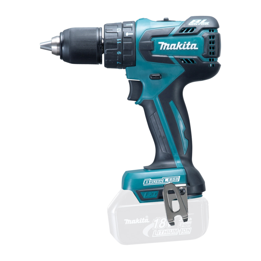
W
[Drawn above is the image
Dimensions: mm (")
Length (L)
Width (W)
238 (9-3/8)*
Height (H)
256 (10-1/8)*
*
: with Battery BL1815
2
*
: with Battery BL1830
3
)
1
PRODUCT
P 1/ 11
L
H
with BL1830.]
192 (7-9/16)
78 (3-1/16)
2
3
Advertisement
Table of Contents

Related Manuals for Makita BHP459


Summary of Contents for Makita BHP459
- Page 1 Description Cordless Hammer Driver Drill ONCEPT AND MAIN APPLICATIONS Model BHP459 Cordless Hammer Driver Drill has been developed specially for light to medium duty drilling and fastening applications. motor (BrushLess DC motor) specially This model is equipped with a basic BLDC designed to provide, above all, more work amount on a single full battery charge.
- Page 2 P 2/ 11 ariation list BHP459 Plastic Battery Battery Housing Model No. Charger carrying cover color Type Quantity case BHP459Z Makita blue BHP459RF BHP459RFE Makita blue DC18RC BL1830 BHP459RFE3 BHP459RFEW White BHP459RH DC18RC BL1815 Makita blue BHP459RHE BHP459SHE DC18SD BL1815 Makita blue Note: All models also include the accessories listed in "Standard equipment"...
- Page 3 P 3/ 11 epair CAUTION: Repair the machine in accordance with “Instruction manual” or “Safety instructions”. [1] NECESSARY REPAIRING TOOLS Code No. Description Use for (Use this tool if Drill chuck cannot be removed by the method of 1R359 Drill chuck removing tool described in “[3]-1 Drill chuck disassembling”.) Hex wrench 10 removing/ mounting Drill chuck...
- Page 4 P 4/ 11 epair [3] DISASSEMBLY/ASSEMBLY [3] -1. Drill Chuck (cont.) ASSEMBLING (1) Seat Drill chuck on Spindle. (Fig. 5) (2) Set the machine to Drill mode, Low gear mode and Forward rotation mode. (Fig. 6) (3) Set Hex wrench 10 to vise. (Refer to Fig. 3) (4) Tighten Drill chuck.
- Page 5 P 5/ 11 epair [3] DISASSEMBLY/ASSEMBLY [3] -2. Gear Assembly, Rotor Section DISASSEMBLING (1) Disassemble Rotor section and Gear assembly. (Figs. 8 and 9) Fig. 8 1. By unscrewing nine 3x16 tapping screws, 2. Remove Gear assembly 3. Remove Speed change lever remove Housing R from Housing L.
- Page 6 P 6/ 11 epair [3] DISASSEMBLY/ASSEMBLY [3] -2. Gear Assembly, Rotor Section (cont.) ASSEMBLING (1) Assemble Gear assembly and Rotor section in the reverse order of disassembly. (Refer to Figs. 9 and 8) Note: Be careful not to pinch your fingers between Stator and Rotor’s fan when assembling Rotor. (Fig. 11) Fig.
- Page 7 P 7/ 11 epair [3] DISASSEMBLY/ASSEMBLY [3] -2. Gear Assembly, Rotor Section (cont.) ASSEMBLING Assemble Gear assembly and Rotor section to Housing L. (Fig. 13) Fig. 13 Projection of Groove of Housing L Gear assembly 1. Make sure to put Leaf spring in place as drawn below.
- Page 8 P 8/ 11 ircuit diagram Fig. D-1 Color index of lead wires' sheath Black Yellow White Orange Blue LED Light Printed Stator wiring Switch board Connector Terminal Connector Controller Terminal...
- Page 9 P 9/ 11 iring diagram Fig. D-2 Wiring to Switch Flag connectors of Lead wires must be connected to Switch so that their wires come to Housing L side. Switch Flag connectors Lead wires Housing L Fig. D-3 Wiring of LED Lead wire Rib C Rib B LED bushing...
- Page 10 P 10/ 11 iring diagram Fig. D-4 Wiring in Housing L Be careful not to put Lead wires on this place. Printed wiring board Put the slack portion of Lead wires Be careful not to put Lead wires of Stator and those of Printed wiring on Ribs A, B and D.
- Page 11 P 11/ 11 iring diagram Fig. D-5 Wiring and Mounting of Printed Wiring Board to Stator By fastening four screws, assemble Printed wiring Lead wires of Printed wiring board must be faced board to Insulator without wobbling. to the opposite side of Lead wires of Stator. Note: The screws must be tightened to 0.3N·m of torque.