Table of Contents
Advertisement
Advertisement
Table of Contents

Related Manuals for Honeywell LYNX Touch 5100


Summary of Contents for Honeywell LYNX Touch 5100
-
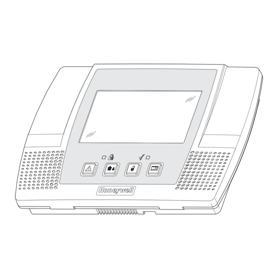
Page 1: Security System
LYNX Touch Security System Programming Guide 800-11060 2/12 Rev. A... -
Page 2: Table Of Contents
Table of Contents Entering Programming Mode............................ 3 Programming the Data Fields........................... 3 Loading a Default Set ............................... 3 Exiting Programming Mode ............................3 Data Fields................................4 Change Installer Code............................4 Program System Type............................4 Program Date and Time............................5 Program Communications............................. 5 Program Zones.............................. -
Page 3: Entering Programming Mode
Entering Programming Mode You may find it convenient to adjust the volume setting before entering the Programming Mode. This will allow you to clearly hear feedback announcements or system beeps. 1. Power up the LYNX Touch control, when the Home Screen appears, select “More”. 2. -
Page 4: Data Fields
Screen Display Function & Programming Options DATA FIELDS Note: If applicable, preprogrammed defaults for the LYNX Touch Control are shown on the screen display. Change Installer Code Installer Code Installer Code Enter 4 digits [The defaulted Installer Code is 4112] 5000-100-129-V0 Program System Type RF Jam... -
Page 5: Program Date And Time
Screen Display Function & Programming Options Multi Mode Serial Multi Mode Serial Enhanced Reports Disabled Disabled Program Date and Time Date Time Date Time Note: If you are installing a GSMVLP5 or ILP5 Communication Module, the time and date will be programmed and updated automatically via Central Station. - Page 6 Screen Display Function & Programming Options Communications Path Communications Path None None WiFi WiFi & GSM Advanced Protection Logic Enabled Disabled Disabled Primary City Identification City ID Enter 2 digits 01-99 Primary Central Station Identification CS ID Enter 2-digits (HEX) 01-FE Primary Subscriber Identification Sub ID...
-
Page 7: Program Zones
Screen Display Function & Programming Options Program Zones Zones Zones Select from the following zone options: 1. New 2. Front Door 5000-100-133-V0 3. Back Door 4.Window 5. Motion Sensor 6.New 7. – 48. New 49. – 56. 4 Button 57. – 64. New 80. -
Page 8: Program Keys
Screen Display Function & Programming Options Chime Chime Supervision Supervision Hardwire Zone RF Zone Temperature Supervised Normal Open Supervised High Temp Normal Closed Unsupervised Low Temp End of Line Program Keys Keys Keys Select from the following options: Edit Add New Delete If add new is selected the following options can be programmed: Key Type... -
Page 9: Program Reporter
Screen Display Function & Programming Options Program Reporter Reporter Reporter Program the following options: Primary CS Info Secondary CS Info Follow Me Phone 1 Follow Me Phone 2 Report Selection Options Downloader Primary Central Station Information Primary CS Info Phone Type Communicator Type Phone Type Phone Type... - Page 10 Screen Display Function & Programming Options Communicator Type Communicator Type None None WiFi WiFi & GSM Note: If IP is selected the Dynamic Priority option will be displayed. Phone Number Phone Number Enter the Secondary Central Station Phone Number (Up to 20 digits) Communicator Type Communicator Type None...
- Page 11 Screen Display Function & Programming Options Report Alarms Report Alarms Disabled Disabled Enabled Report Troubles Report Troubles Disabled Disabled Enabled Report Open/Close Report Open/Close Disabled Disabled Enabled Report Tests Report Tests Disabled Disabled Enabled Follow Me Phone 2 Follow Me Phone 2 Choose from the following options: Phone Type Phone Number...
- Page 12 Screen Display Function & Programming Options Event Log Full Event Log Full Disabled Enabled Enabled Trouble Trouble Disabled Enabled Enabled Trouble Restore Trouble Restore Disabled Enabled Enabled Alarm Restore Alarm Restore Disabled Enabled Enabled Alarm Cancel Alarm Cancel Disabled Enabled Enabled Test Test...
-
Page 13: Program Sounder
Screen Display Function & Programming Options Alarm Report Delay Alarm Report Delay No Delay No Delay 15 Sec. 30 Sec. 45 Sec. First Report Offset First Report Offset 6 Hrs 6 Hrs 12 Hrs 18 Hrs 24 Hrs Report Frequency Report Frequency Never Never... -
Page 14: Program System Settings
Screen Display Function & Programming Options Arm Confirm Arm Confirm None None All RF RF Key Fob RF Keypad Alarm Options Alarm Options Unlimited Unlimited Program System Settings System Settings System Settings Choose from the following options: Entry Delay 1 Entry Delay 1 Exit Delay Backlight Timeout... - Page 15 Screen Display Function & Programming Options Exit Warning Exit Warning Auto Stay Arming Auto Stay Arming Lack of Usage Notify Lack of Usage Notify Disabled Disabled 1 Day 7 Days 27 Days 90 Days 180 Days 365 Days Power-Up in Previous State Power-Up in Previous Display Alarm Cancel Display Alarm Cancel...
-
Page 16: Program The Z-Wave Module
Screen Display Function & Programming Options Program the Z-Wave Module Z-Wave Z - Wave Note: This procedure must be completed any time that the panel has been defaulted or updated. 5100-100-067-V0 Z-Wave Z-Wave Select from the following options: Enabled-Installed Telephone Enabled –... -
Page 17: Zone Programming Worksheet
Zone Programming Worksheet Fill in the required data on this worksheet, then follow the programming procedure. See Explanation of Zone Assignment Table Headings (defaults shown are for Table 1) Zone Loop Device Response Transmitter Zone Type Type Report Chime Supervision Serial Number Descriptor End of Line... -
Page 18: Explanation Of Zone Assignment Table Headings
Zone Programming Worksheet Zone Loop Device Response Transmitter Zone Type Type Report Chime Supervision Serial Number Descriptor 4 Button (Key) Arm Away Button 4 Button (Key) Disarm Button 4 Button (Key) Arm Stay Button 4 Button (Key) No Response Button 4 Button (Key) Arm Away Button... -
Page 19: 5800 Series Transmitter Loop Numbers Diagram
5800 Series Transmitter Loop Numbers LOOP 1 LOOP 1 (LOW (LOW SENSITIVITY SENSITIVITY LOOP LOOP 2 LOOP 2 LOOP 1 (HIGH (HIGH SENSITIVITY) SENSITIVITY) LOOP LOOP 3 (TEMP) LOOP 3 (TEMP) LOOP 4 (TAMPER) LOOP 4 (TAMPER) 5 8 0 0 R L 5 8 0 0 C O 5 8 0 0 M i c r a 5 8 0 0 P I R - R E S... -
Page 20: Programming Default Tables
Programming Default Tables Program Function Table 1 Table 2 Table 3 Table 4 4112 4112 4112 4112 Installer Code System Type RF Jam Disabled Disabled Disabled Disabled Speaker Phone Enabled Enabled Enabled Enabled Two Way Voice Disabled Disabled Disabled Disabled RF House Code Phone Notification Disabled... - Page 21 Program Function Table 1 Table 2 Table 3 Table 4 Follow Me Phone 1 Phone Type None None None None Phone Number Blank Blank Blank Blank Report All Press To Report All Press To Report All Press To Report All Press To Report All Report Alarms Disabled...
- Page 22 Program Function Table 1 Table 2 Table 3 Table 4 Power-Up In Previous Display Alarm Cancel Display Exit Time Cross Zone Delay 3 Minutes None None None Cross Zone 1 Disabled Disabled Disabled Disabled Cross Zone 2 Disabled Disabled Disabled Disabled Z-Wave Z-Wave...
-
Page 23: Lynx Touch Summary Of Connections Diagram
-23-... - Page 24 2 Corporate Center Drive, Suite 100 P.O. Box 9040, Melville, NY 11747 Copyright © 2012 Honeywell International Inc. www.honeywell.com/security Ê800-11060WŠ 800-11060 2/12 Rev. A...