Honeywell lynx touch User Manual
Hide thumbs
Also See for lynx touch:
- User manual (96 pages) ,
- Quick manual (4 pages) ,
- Step-by-step manual (2 pages)

Related Manuals for Honeywell lynx touch


Summary of Contents for Honeywell lynx touch
- Page 1 LYNX Touch Security System User Guide 800-10615V1 12/12 Rev. A LYNX Touch L5100 Series...
- Page 2 Your Honeywell security system is designed for use with devices manufactured or approved by Honeywell for use with your security system. Your Honeywell security system is not designed for use with any device that may be attached to your security system's control or other communicating bus if Honeywell has not approved such device for use with your security system.
- Page 3 TABLE OF CONTENTS TABLE OF CONTENTS TABLE OF CONTENTS TABLE OF CONTENTS – 3 –...
- Page 4 TABLE OF CONTENTS TABLE OF CONTENTS TABLE OF CONTENTS TABLE OF CONTENTS – 4 –...
-
Page 5: System Overview
SYSTEM OVERVIEW SYSTEM OVERVIEW SYSTEM OVERVIEW SYSTEM OVERVIEW Features General Information IMPORTANT SECURITY NOTICE Your key fob is similar to your keys or access card. If lost or stolen, another person can compromise your security system. Immediately notify your Dealer/Installer of a lost or stolen key fob. The Dealer/Installer will then remove the key fob programming from the security system. - Page 6 SYSTEM OVERVIEW SYSTEM OVERVIEW SYSTEM OVERVIEW SYSTEM OVERVIEW Features Zones Fire Protection Carbon Monoxide Burglary Protection – 6 –...
-
Page 7: General Operation
SYSTEM OVERVIEW SYSTEM OVERVIEW SYSTEM OVERVIEW SYSTEM OVERVIEW General Operation Security Codes Alarms Important Note If your system is equipped to report alarms over the internet via a WiFi Communications module, your router must remain powered-on at all times. Ask your Installer about this feature for additional information Two-Way Voice Feature –... - Page 8 SYSTEM OVERVIEW SYSTEM OVERVIEW SYSTEM OVERVIEW SYSTEM OVERVIEW General Operation – 8 –...
-
Page 9: Quick View Of System Functions
To disarm system and silence alarms: ......Depress “Off’” key or “Disarm” icon and enter Code* * During Entry Delay or when an Alarm Condition exists, the LYNX Touch can be disarmed by entering the User Code. Entering the OFF key is not required To bypass a zone(s): .......... -
Page 10: About The Touch Screen Control
SYSTEM OVERVIEW SYSTEM OVERVIEW SYSTEM OVERVIEW SYSTEM OVERVIEW About the Touch screen Control General – 10 –... - Page 11 SYSTEM OVERVIEW SYSTEM OVERVIEW SYSTEM OVERVIEW SYSTEM OVERVIEW About the Touch screen Control Note: The system functions described below are for reference only and require additional key entries to activate. Index Item Description Display Color Liquid Crystal Display (LCD) Touch screen. Displays system status icons, Window time, system status information, user menus and the virtual keypad.
-
Page 12: About The Display And Indicators
SYSTEM OVERVIEW SYSTEM OVERVIEW SYSTEM OVERVIEW SYSTEM OVERVIEW About the Display and Indicators Display Definitions DEFINITION ICON TEXT Displayed along with the the text “Ready To Arm” when Ready to system is Disarmed and ready to arm. “Armed Away” is displayed along the top of the screen. An Armed armed away icon along with “Armed Away”... - Page 13 SYSTEM OVERVIEW SYSTEM OVERVIEW SYSTEM OVERVIEW SYSTEM OVERVIEW About the Display and Indicators DEFINITION ICON TEXT The alarm (bell) icon when a burglary alarm is activated. Alarm 99 “Alarm” is also displayed in a red status bar along the top of Police the screen.
-
Page 14: Navigating Menus
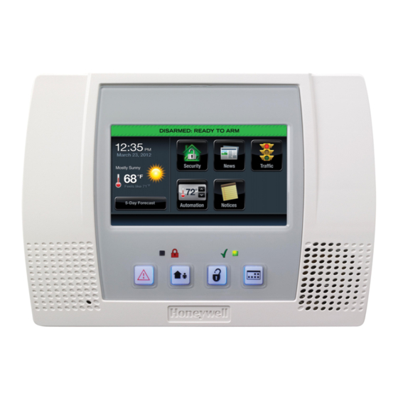
Dashboard Screen Note: Access to Text Messages, Weather, News and Traffic and other web content requires Total Connect Services. Ask your Installer, which of these features have been programmed in your system. LYNX Touch Dashboard Screen (Typical) – 14 –... -
Page 15: Navigation Keys
“Save” to accept. Function Keys Four Function Keys allow you to quickly access Panic functions, army the system in Away mode, disarm the system and reurn to the home screen. LYNX Touch Security Home Screen (page 1) – 15 –... - Page 16 SYSTEM OVERVIEW SYSTEM OVERVIEW SYSTEM OVERVIEW SYSTEM OVERVIEW Navigating Menus Menu Screens Menus Unrestricted Menu – 16 –...
- Page 17 SYSTEM OVERVIEW SYSTEM OVERVIEW SYSTEM OVERVIEW SYSTEM OVERVIEW Navigating Menus Master Menu – 17 –...
- Page 18 SECURING THE PREMISES URING THE PREMISES URING THE PREMISES URING THE PREMISES System Status General Information System Can Be Armed – 18 –...
-
Page 19: Securing The Premises
SECURING THE PREMISES SECURING THE PREMISES SECURING THE PREMISES SECURING THE PREMISES Arming the System Arming in Stay Mode The Babysitter Code and Installer Code cannot disarm the system unless it was used to arm the system. In addition, if the system is armed by pressing via Quick-Arming, neither the Babysitter Code nor Installer Code can disarm the system. - Page 20 SECURING THE PREMISES SECURING THE PREMISES SECURING THE PREMISES SECURING THE PREMISES Arming the System At the end of the exit delay the system announces “Armed Stay” and displays the “Armed Stay” screen. If an invalid User Code is entered, the system will return to the home screen. Auto Stay Feature NOTE: If the exit route entry/exit sensor is in a check condition or has been bypassed it will result in a loss of interior...
- Page 21 SECURING THE PREMISES SECURING THE PREMISES SECURING THE PREMISES SECURING THE PREMISES Arming the System Arming In Away Mode The Babysitter Code and Installer Code cannot disarm the system unless it was used to arm the system. In addition, if the system is armed by pressing via Quick-Arming, neither the Babysitter Code nor Installer Code can disarm the system.
- Page 22 SECURING THE PREMISES SECURING THE PREMISES SECURING THE PREMISES SECURING THE PREMISES Arming the System If “Exit Warning” has been enabled, the system will continue to beep throughout the exit delay. Rapid beeps will sound for the final 10 seconds of the delay period. At the end of the exit delay the system will announce “Armed Away”...
-
Page 23: Quick Exit
SECURING THE PREMISES SECURING THE PREMISES SECURING THE PREMISES SECURING THE PREMISES Arming the System Arming the System with no delay (Instant) To Arm the System with No Delay (Instant) Select the “Delay” tab on the home screen. The icon “toggles” and “Instant” is displayed. Arm the system in the “Stay”... -
Page 24: Entry/Exit Delays
SECURING THE PREMISES SECURING THE PREMISES SECURING THE PREMISES SECURING THE PREMISES Entry/Exit Delays Entry/Exit Delays Entry/Exit Delays Entry/Exit Delays Exit Delay Restarting Exit Delay While System Armed Exit Alarms – 24 –... -
Page 25: Entry Delay
SECURING THE PREMISES SECURING THE PREMISES SECURING THE PREMISES SECURING THE PREMISES Entry/Exit Delays Entry/Exit Delays Entry/Exit Delays Entry/Exit Delays Entry Delay system. 45, 60, 90 seconds, 2 minutes None, 15, 30, 45, 60, 90 seconds, 2, 3, 4 minutes None, 15, 30, 45, 60, 90 seconds, 2, 3, 4 minutes None, 15, 30, 45, 60, 90 seconds, 2 minutes None, 15, 30, 45, 60, 90 seconds, 2 minutes... -
Page 26: Disarming The System
SECURING THE PREMISES SECURING THE PREMISES SECURING THE PREMISES SECURING THE PREMISES Disarming the System Disarming the System and Silencing Alarms Select the “Disarm” icon or depress the “Off” key. The system beeps once and displays a keypad. Enter a valid Code. The system beeps once and announces “Disarmed Ready to Arm”. - Page 27 SECURING THE PREMISES SECURING THE PREMISES SECURING THE PREMISES SECURING THE PREMISES Disarming the System Disarming the System During Entry Delay Upon entering the premise when the system is armed, the control announces “disarm system now”. Enter a valid Code. The system beeps once and announces “Disarmed Ready to Arm”.
-
Page 28: Bypassing Protection Zones
SECURING THE PREMISES SECURING THE PREMISES SECURING THE PREMISES SECURING THE PREMISES Bypassing Protection Zones Bypassing Individual Zones Bypassing Zones 1. With the system in the disarmed state, select the “Zones” icon. The system displays the Zones/Bypass screen. 2. Select the zone(s) that you wish to bypass and then select “Bypass”... - Page 29 SECURING THE PREMISES SECURING THE PREMISES SECURING THE PREMISES SECURING THE PREMISES Bypassing Protection Zones Displaying/Clearing Bypassed Zones 1. With the system in the disarmed state, select the “Zones” icon. The system displays the Zone screen and the status for each zone will be indicated.
-
Page 30: Panic Keys
SECURING THE PREMISES SECURING THE PREMISES SECURING THE PREMISES SECURING THE PREMISES Panic Keys Panic Keys Note: Your installer should advise which functions are active in your system. Icon Function When activated, alerts the alarm monitoring company that a fire condition exists. When activated, alerts the alarm monitoring company that a police emergency exists. - Page 31 SECURING THE PREMISES SECURING THE PREMISES SECURING THE PREMISES SECURING THE PREMISES Panic Keys Activating a Panic Alarm 1. With the system in the disarmed or armed state, depress and hold the “Panic” key until the system displays the Panic screen (approximately 3-4 seconds).
-
Page 32: Chime Mode
SECURING THE PREMISES SECURING THE PREMISES SECURING THE PREMISES SECURING THE PREMISES Chime Mode Chime Mode Turning Chime Mode On or Off 1. With the system in the disarmed state, select the “Settings” icon from the second page of the Home Screen. The system displays the Settings screen. -
Page 33: Voice Mode
SECURING THE PREMISES SECURING THE PREMISES SECURING THE PREMISES SECURING THE PREMISES Voice Mode Voice Mode Turning Voice Mode On or Off 1. With the system in the disarmed or armed state, select the “Settings” icon from the second page of the Home Screen. The system displays the Keypad screen. -
Page 34: User Functions
USER FUNCTIONS USER FUNCTIONS USER FUNCTIONS USER FUNCTIONS User Access General Information Adding a User 1. With the system in the disarmed state, select the “Tools” icon from the second page of the Home Screen. The system displays the Keypad screen. –... - Page 35 USER FUNCTIONS USER FUNCTIONS USER FUNCTIONS USER FUNCTIONS User Access 2. Enter your 4-digit Master User Code. The system displays Master User programming screen. 3. Select the “Users” icon. The system displays the Master User screen. 4. Select the “Add New” key. The system displays the User screen.
- Page 36 USER FUNCTIONS USER FUNCTIONS USER FUNCTIONS USER FUNCTIONS User Access 6. If desired you can enter a User Name. Select the “Clear” key and then enter up to 10 characters of text. Note: Select the “ABC…” key to switch the keyboard between upper/lower case or the “123!@#”...
- Page 37 USER FUNCTIONS USER FUNCTIONS USER FUNCTIONS USER FUNCTIONS User Access Editing/Deleting a User 1. With the system in the disarmed state, select the “Tools” icon from the second page of the Home Screen. The system displays the Keypad screen. 2. Enter your 4-digit Master User Code. The system displays the Master User programming screen.
- Page 38 USER FUNCTIONS USER FUNCTIONS USER FUNCTIONS USER FUNCTIONS User Access 5. If desired you can revise a User Name. Select the “Clear” key and then enter the desired text. 6. Once you are finished, select “Done”. The system displays the Keypad screen. If you wish to change the assigned User Code, proceed to Step 7 otherwise proceed to Step 7.
-
Page 39: View Events
USER FUNCTIONS USER FUNCTIONS USER FUNCTIONS USER FUNCTIONS View Events Viewing System Events 1. With the system in the disarmed state, select the “Tools” icon from the second page of the Home Screen. The system displays the Keypad screen. 2. Enter your 4-digit Master User Code. The system displays Master... - Page 40 USER FUNCTIONS USER FUNCTIONS USER FUNCTIONS USER FUNCTIONS View Events 4. If you wish to view specific system history, select “All”. The system displays a new menu. 5. Select from the menu to display the specific event types that you wish to view. Note: Only event types...
-
Page 41: Message Recording And Playback
USER FUNCTIONS USER FUNCTIONS USER FUNCTIONS USER FUNCTIONS Message Recording and Playback NOTES: (1) If the system loses electrical power, all messages will be erased. (2) Message Play/Record will not be available if a report must be sent. Entering Message Mode With the system in the disarmed state, select the “Message”... - Page 42 USER FUNCTIONS USER FUNCTIONS USER FUNCTIONS USER FUNCTIONS Message Recording and Playback 6. When you have finished recording, select “ ”. The system displays the recorded messages. 7. To record additional messages (if recording time is available) repeat steps 1 through 3. NOTE: If you are trying to record a new message and the message center is already full, “Add New”...
-
Page 43: System Settings
USER FUNCTIONS USER FUNCTIONS USER FUNCTIONS USER FUNCTIONS System Settings Change System Settings 1. With the system in the disarmed or armed state, select the “Settings” icon from the second page of the Home Screen. The system displays the Settings screen. 2. - Page 44 USER FUNCTIONS USER FUNCTIONS USER FUNCTIONS USER FUNCTIONS Clock/Calendar Note: If your system is equipped with a GSMVLP5 or ILP5 Communication Module, the time and date will be programmed and updated automatically via Central Station. You may still program the correct Time Zone as shown below.
- Page 45 USER FUNCTIONS USER FUNCTIONS USER FUNCTIONS USER FUNCTIONS Clock/Calendar 4. Select the correct month by using the “ ” and “ ”. 5. Select the correct year by using the “ ” and “ ”. 6. Select the correct day on the calendar. 7.
- Page 46 USER FUNCTIONS USER FUNCTIONS USER FUNCTIONS USER FUNCTIONS Clock/Calendar 12. Select “Start Month”. The system displays a calendar. Select the correct month. 13. Select “Start Week”. The system will toggle between: Second Third Fourth Last Next to Last 3rd from Last First 14.
- Page 47 USER FUNCTIONS USER FUNCTIONS USER FUNCTIONS USER FUNCTIONS Automation General Information Note: Switches, Thermostats, Locks, Tools, and Scenes options will only appear when Z-wave has been enabled. Refer to the Home Automation Guide PN 800-11309V1 for information regarding these features. Schedules Programming a Scheduled Function 1.
- Page 48 USER FUNCTIONS USER FUNCTIONS USER FUNCTIONS USER FUNCTIONS Automation 3. Select “Add New”. The system displays the scheduling options screen. 4. Select “Name”. The system displays a keypad. 5. Enter a name (up to 13 digits long) for the scheduled function on the displayed keypad then select “Done”.
- Page 49 USER FUNCTIONS USER FUNCTIONS USER FUNCTIONS USER FUNCTIONS Automation 9. If Auto Stay is selected, select “Clear” then enter a 4-digit time on the displayed keypad then select “Save”. If “Rules” is selected proceed to Step 11. If “Disarm Notification” is selected proceed to Step 12.
- Page 50 USER FUNCTIONS USER FUNCTIONS USER FUNCTIONS USER FUNCTIONS Automation Rules The following options are programmed in this section: Programming Field Action Rule 1 - 20: Select Rule 1 -20 Note: Rules 21-40 are only accessible through TotalConnect Service. Name: Name the device Type: Select the output type Action:...
- Page 51 USER FUNCTIONS USER FUNCTIONS USER FUNCTIONS USER FUNCTIONS Automation 3. Select a “Rules” key followed by the Edit button. The system displays a keyboard. Note: Rules 21-40 only accessible through TotalConnect Service. 4. If desired you can enter a Rule Name. Select the “Clear”...
- Page 52 USER FUNCTIONS USER FUNCTIONS USER FUNCTIONS USER FUNCTIONS Automation 7. Select “Action”. Dependant upon the Type selected previously, the system scrolls between several options: None Permanent On On for 2 sec Pulsing Send Run Scene* * If Scene was selected in step 6 refer to the Home Automation Guide PN 800-11309V1 for information.
- Page 53 USER FUNCTIONS USER FUNCTIONS USER FUNCTIONS USER FUNCTIONS Automation 9. Select “Stop Zone Type” The system displays the same options as the previous step. Note: If a Rule is being used to trigger a Z-Wave door lock, when the system is Armed Stay or Armed Away, it is recommended that “End of Exit Delay”...
- Page 54 USER FUNCTIONS USER FUNCTIONS USER FUNCTIONS USER FUNCTIONS Automation 13. Select the First, Second or Third “Start Zone” Select the Zone from the list displayed by the system. 14. Select the First, Second or Third “Stop Zone” Select the Zone from the list displayed by the system.
- Page 55 USER FUNCTIONS USER FUNCTIONS USER FUNCTIONS USER FUNCTIONS Reminders Programming a Reminder 1. With the system in the disarmed state, select the “Tools” icon from the second page of the Home Screen. The system displays the Keypad screen. 2. Enter your 4-digit Master User Code. The system displays Master...
- Page 56 USER FUNCTIONS USER FUNCTIONS USER FUNCTIONS USER FUNCTIONS Reminders 4. Select “Add New”. The system displays the Reminder programming screen. 5. Select “Name”. Enter a name for the scheduled function on the displayed keypad then select “Done”. 6. Select “Frequency” then select one of the following displayed options: None Once...
- Page 57 USER FUNCTIONS USER FUNCTIONS USER FUNCTIONS USER FUNCTIONS Reminders 10. If a “Follow Me” phone number(s) was programmed by your installer you can send a reminder to the phone number(s). Select “Follow Me” option. The system toggles between “Disabled”, “To Ph. 1”, “To Ph. 2” and “To Ph.
-
Page 58: Wifi Configuration
USER FUNCTIONS USER FUNCTIONS USER FUNCTIONS USER FUNCTIONS WiFi Configuration View/Join Available WiFi Networks 1. At the Master User screen select the WiFi Config icon. The system displays the WiFi options screen. 2. Select the “Scan Access Points” button to view the available networks. - Page 59 USER FUNCTIONS USER FUNCTIONS USER FUNCTIONS USER FUNCTIONS WiFi Configuration Manually Configure Access Point 1. At the Master User screen select the WiFi Config icon. The system displays the WiFi options screen. 2. Select the “Manually Configure AP” button to view the available networks.
- Page 60 USER FUNCTIONS USER FUNCTIONS USER FUNCTIONS USER FUNCTIONS WiFi Configuration A router is required if you are using an Auxilary Keypad. The router must be powered on and connected for WiFi operation to occur. Enrolling/Syncing Auxiliary Keypads Viewing or Deleting Enrolled Keypads 1.
-
Page 61: Speaker Phone Feature
USER FUNCTIONS USER FUNCTIONS USER FUNCTIONS USER FUNCTIONS Speaker Phone Feature NOTE: The system will enter the Speaker Phone mode even if an alarm or trouble is stored in the system memory. Do not use the speaker phone as the only telephone in your home since in some special cases the speaker phone is not functional. - Page 62 USER FUNCTIONS USER FUNCTIONS USER FUNCTIONS USER FUNCTIONS Speaker Phone Feature Placing a Call 1. With the system in the disarmed or armed state, select the “Phone” icon from the Home Screen. The system displays the Keypad screen. 2. Select the “Talk” icon and then enter the number you wish to dial.
-
Page 63: Remote Phone Control Feature
USER FUNCTIONS USER FUNCTIONS USER FUNCTIONS USER FUNCTIONS Remote Phone Control Feature Using Remote Phone Control Feature Remote Phone Control Commands Enter User Code (within eight seconds). Upon entering remote phone control mode the Lynx will announce “System, enter code”. To remotely disarm system: .............. -
Page 64: Remote Services
USER FUNCTIONS USER FUNCTIONS USER FUNCTIONS USER FUNCTIONS Remote Services – 64 –... -
Page 65: Slide Show
USER FUNCTIONS USER FUNCTIONS USER FUNCTIONS USER FUNCTIONS Slide Show Activating the Slide Show 1. With the system in the disarmed state, select the “Tools” icon from the second page of the Home Screen. The system displays the Keypad screen. 2. - Page 66 USER FUNCTIONS USER FUNCTIONS USER FUNCTIONS USER FUNCTIONS Slide Show 4. Select the “Slide Show” icons that you do not wish to display or select “Delete All”. Use the “ ” “ ” buttons to scroll to second and subsequent pages of screens. 5.
-
Page 67: General Information
1. Should you become aware of a fire emergency before your detectors sense the problem, go to the LYNX Touch and press and hold the panic button and then select the Fire icon. The alarm will sound and an alarm will be transmitted to the central station. - Page 68 /CO ALARM SYSTEM ALARM SYSTEM FIRE FIRE ALARM SYSTEM ALARM SYSTEM National Fire Protection Association’s Smoke Detector Recommendations LYNX Touch is not intended for UL985 Household Fire applications unless a 24-hour backup battery (P/N LYNXRCHKIT-SHA) is installed. – 68 –...
- Page 69 FIRE FIRE/CO /CO ALARM SYSTEM ALARM SYSTEM FIRE FIRE ALARM SYSTEM ALARM SYSTEM Emergency Evacuation LYNX Touch is not intended for UL985 Household Fire applications unless a 24-hour backup battery (P/N LYNXRCHKIT-SHA) is installed. – 69 –...
-
Page 70: System Functions
SYSTEM FUNCTIONS SYSTEM FUNCTIONS SYSTEM FUNCTIONS SYSTEM FUNCTIONS Testing the System (to be conducted weekly) Test Modes NOTE: An alarm message will not be sent to your alarm monitoring company during these tests. Entering Test Mode Testing or Rebooting the System 1. - Page 71 SYSTEM FUNCTIONS SYSTEM FUNCTIONS SYSTEM FUNCTIONS SYSTEM FUNCTIONS Testing the System (to be conducted weekly) 3. Select the “Test” icon. The system displays the Test screen. 4. Select the “Walk Test”, “Dialer Test”, “Comm. Test” or “Reboot” icon. If Walk Test is selected proceed to Step 5.
- Page 72 SYSTEM FUNCTIONS SYSTEM FUNCTIONS SYSTEM FUNCTIONS SYSTEM FUNCTIONS Testing the System (to be conducted weekly) Test Communications Test Message Sent Test Message Failed – Not Registered! Exiting Test Mode NOTE: If the Walk Test mode is inadvertently left active, it automatically turns off after 4 hours. The Dialer Test mode will remain active until exited via an Off sequence.
-
Page 73: Routine Care
SYSTEM FUNCTIONS SYSTEM FUNCTIONS SYSTEM FUNCTIONS SYSTEM FUNCTIONS Maintaining your system Routine Care Cleaning the Touch screen 1. With the system in the disarmed or armed state, select the “Settings” icon from the second page of the Home Screen. The system displays the Settings”... - Page 74 Factors such as humidity, high or low temperatures, and large swings in temperature may all lead to the reduction of actual battery life in an installation. Changing the LYNX Touch Series System Battery NOTE: The battery pack (P/N LYNXRCHKIT-SC or LYNXRCHKIT-SHA) should be changed every four years and must be replaced by a qualified service technician.
- Page 75 SUMMARY OF AUDIBLE & VISUAL SUMMARY OF AUDIBLE & VISUAL NOTIF NOTIFICATION ICATIONS S S S SUMMARY OF AUDIBLE SUMMARY OF AUDIBLE & VISUAL & VISUAL NOTIF NOTIF ICATION ICATION SOUND CAUSE ANNOUNCEMENT* INTERRUPTED FIRE ALARM (3 beeps) fire alarm + zone voice descriptor CARBON MONOXIDE ALARM (4 beeps) Carbon monoxide alarm + zone voice descriptor (Voice descriptor is interlaced with the sounder...
-
Page 76: Summary Of Audible & Visual Notifications
SUMMARY OF AUDIBLE & VISUAL NOTIFICATIONS SUMMARY OF AUDIBLE & VISUAL NOTIFICATIONS SUMMARY OF AUDIBLE & VISUAL NOTIFICATIONS SUMMARY OF AUDIBLE & VISUAL NOTIFICATIONS System Displays DISPLAY DEFINITION DISPLAY DEFINITION AC Loss Door Open Alarm Window Open (intrusion) Armed Away Exit Active Armed Stay Fire... -
Page 77: Zone Status Icons
SUMMARY OF AUDIBLE & VISUAL NOTIFICATIONS SUMMARY OF AUDIBLE & VISUAL NOTIFICATIONS SUMMARY OF AUDIBLE & VISUAL NOTIFICATIONS SUMMARY OF AUDIBLE & VISUAL NOTIFICATIONS Zone Status Icons DEFINITION DEFINITION ICON ICON Alarm Trouble (red) Fault (Yellow) Bypass Ready LED Meanings Note: When the system is armed, the Ready LED turns off. -
Page 78: Regulatory Agency Statements
REGULATORY AGENCY STATEMENTS REGULATORY AGENCY STATEMENTS REGULATORY AGENCY STATEMENTS REGULATORY AGENCY STATEMENTS Federal Communications Commission (FCC) Part 15 The user shall not make any changes or modifications to the equipment unless authorized by the Installation Instructions or User's Manual. Unauthorized changes or modifications could void the user's authority to operate the equipment. CLASS B DIGITAL DEVICE STATEMENT NOTE: This equipment has been tested and found to comply with the limits for a Class B digital device, pursuant to part 15 of the FCC Rules. - Page 79 5. RF Exposure WARNING: The LYNX Touch must be installed to provide a separation distance of at least 7.8 in (20 cm) from all persons and not co-located or operated in conjunction with any other transmitter – 79 –...
- Page 80 IN THE EVENT OF TELEPHONE OPERATIONAL PROBLEMS – 80 –...
- Page 81 – 81 –...
- Page 82 – 82 –...
- Page 83 – 83 –...
- Page 84 – 84 –...
- Page 85 – INDEX – – 85 –...
- Page 86 – 86 –...
- Page 87 TWO YEAR LIMITED WARRANTY – 87 –...
- Page 88 Ê800-10615V1†Š...