Sign In
Upload
Manuals
Brands
Siemens Manuals
I/O Systems
ET 200
Siemens ET 200 Manuals
Manuals and User Guides for Siemens ET 200. We have
2
Siemens ET 200 manuals available for free PDF download: Manual
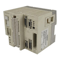
Siemens ET 200 Manual (331 pages)
Distributed I/O System
Brand:
Siemens
| Category:
I/O Systems
| Size: 2.72 MB
Table of Contents
Edition
2
Table of Contents
6
System Overview
17
Memory Card and 32 K EEPROM
17
1.1 What Is the ET 200 Distributed I/O System
18
System Overview
18
Graphical User Interface
20
Tables
21
1.2 Expansion Options of the ET 200 Distributed I/O System
21
Figures
21
Permissible Cable Length of a Bus Segment as a Function of Baud Rate
21
Structure of a Bus Segment
21
Linking Bus Segments with RS 485 Repeaters
22
Permissible Cable Length of a Segment Incorporating RS 485 Repeaters with Order Number 6ES7 972-0AA00-0XA0
23
1.3 DP Masters in the ET 200 Distributed I/O System
24
IM 308-C Master Interface
25
S5-95U Programmable Controller with DP Master Interface
26
1.4 DP Slaves in the ET 200 Distributed I/O System
27
1.5 SINEC L2 DP Field Bus
29
1.6 COM ET 200 Windows Parameterization Software
30
Purpose of the COM ET 200 Windows Parameterization Software
30
1.7 Memory Card and 32 K EEPROM
31
1.8 Network Components
32
Bus Connector
33
Mechanical Design and Applications for IP 20 Bus Connectors
33
RS 485 Repeater
34
RS 485 Repeater with Order Number 6ES7
34
Procedure - from Planning to Initial Operation
35
Planning the Layout
36
Structuring the ET 200 Distributed I/O System
37
Setting up the ET 200
37
COM ET 200 Windows and STEP 5 in Parallel (IM 308-C)
38
COM ET 200 Windows and STEP 5 in Parallel (S5-95U)
39
Parameterization with COM ET 200 Windows
40
Parameterizing and Saving the Configuration (IM 308-C)
40
Parameterizing and Saving the Configuration (S5-95U)
41
Writing the STEP 5 Application Program
42
Initial Operation of the ET 200
43
Initial Operation of the ET 200 (with IM 308-C)
43
Initial Operation of the ET 200 (with S5-95U)
43
IM 308-C Master Interface and Memory Card
44
IM 308-C Master Interface
44
Function and Appearance of the IM 308-C
45
IM 308-C Master Interface
45
Controls and Features of the IM 308-C Master Interface
46
Meanings of "BF" LED on the IM 308-C Master Interface
47
Meanings of the Leds on the IM 308-C Master Interface
47
Technical Data of the IM 308-C
49
Block Diagram of the IM 308-C
49
Maximum Consistent Data Lengths in Bytes for IM 308-C as DP Master
50
Installing the IM 308-C
51
Slots in the S5-115U System, CR 700-0 Module Rack
51
Slots in the S5-115U System
51
Slots in the S5-135U/S5-155U System
52
Installing the Memory Card
53
Loading the Operating System of the IM 308-C from the Memory Card
54
Flashing Code Output by Leds on IM 308-C When the Operating System Is
55
Loaded from Memory Card
55
3.6 IM 308-C as DP Slave
56
Method of Operation, IM 308-C as DP Slave
56
Maximum Consistent Data Lengths in Bytes for IM 308-C as DP Slave
57
Structure of Device-Specific Diagnostics of the IM 308-C as DP Slave
58
Design and Method of Operation of the S5-95U with DP Master Interface
59
Design of the S5-95U
60
Front View of the S5-95U with DP Master Interface
60
The Indicators, Controls and Interfaces of the S5-95U
60
Significance of the "BF", "RUN" and "STOP" Leds of the S5-95U
62
Pin Assignment of the DP Master Interface
63
Pin Assignment of the DP Master Interface on the S5-95U
63
Exchange of Data between S5-95U and DP Slaves
64
ET 200 Distributed I/O System EWA 4NEB 780 6000-02A
65
Principle of Data Exchange between S5-95U and DP Slave
65
Technical Data of the S5-95U
66
Technical Data of the S5-95U with DP Master Interface
66
Installing S5-95U and 32 K EEPROM
68
5 Routing Cables; Connecting and Installing Bus Connectors
70
5.1 Notes on Routing Cables
70
In-Building Cable Routing
70
General Rules and Regulations for Operation of ET 200
71
In-Building Cable Routing
73
Outdoor Cable Routing
75
Potential Equalization
76
Cable Shielding
77
Securing Shielded Cables with Cable Clamps and Cable Ties
78
Measures to Prevent Interference Voltages
79
Special Measures for Interference-Proof Operation
81
Circuits for DC-Actuated Coils
81
Circuits with AC-Actuated Coils
81
Measures for Suppressing Interference from Fluorescent Tubes in Cabinets
82
5.2 Bus Connector: Mechanical Design and Applications
83
IP 20 Bus Connectors, Mechanical Design and Applications
83
RS 485-Repeaters
83
Bus Connector with Order Number 6ES5
84
Bus Connector with Order Number 6ES7 972-0B.10
84
Bus Connector with Order Number 6ES7 972-0B.20
85
Pin Assignment of the 9-Pin Sub-D Male Adapter
85
5.3 Connecting the Bus Cable to the Bus Connector
86
Properties of the SINEC L2 Bus Cable
86
Boundary Conditions for Laying the Indoor Bus Cable
86
Permissible Cable Lengths for a Segment Using RS 485 Repeaters with Order Number 6ES7 972-0AA00-0XA0
87
Length of Droplines Per Segment
87
Connecting Bus Cable to Bus Connectors with Order Number 6ES5
88
Connecting Bus Cable to Bus Connector (6ES5 ...)
89
Connecting Bus Cable (6ES7 972-0B.10
90
Connecting Bus Cable to Bus Connectors with Order Number 6ES7 972-0B.20
91
Connecting Bus Cable to Bus Connector (6ES7 972-0B.20 ...)
92
5.4 Connecting the Bus Connector to the Module
93
RS 485 Repeaters: Installing, Connecting and Operating
94
The RS 485 Repeater: Scope of Application
95
Maximum Cable Length of a Segment
95
Maximum Cable Length between Two Stations
95
Mechanical Design of the RS 485 Repeater with Order Number
96
Description and Functions of the RS 485 Repeater
96
Technical Data of the RS 485 Repeater
97
Block Diagram of the RS 485 Repeater
98
Pin Assignment of the 9-Pin Sub-D Adapter (PG/OP Interface)
98
Configuration Options with the RS 485 Repeater
99
Setting of the Terminating Resistor
99
Two Bus Segments Connected to the RS 485 Repeater
100
Installing and Removing the RS 485 Repeater
101
Mounting the RS 485 Repeater on the Busbar for S7-300
101
Removing the RS 485 Repeater from the Busbar for S7-300
102
Grounded/Non-Grounded Operation of the RS 485 Repeater
103
ET 200 Bus Segments Operating as Non-Grounded Segments
103
Top View of the RS 485 Repeater with Jumper
103
Connecting the Voltage Supply
104
Connecting the Bus Cable
105
Length of Stripped Ends for Connection to RS 485 Repeater
105
Starting COM ET 200 Windows
106
Adapters for COM ET 200 Windows
107
Scope of Application and Preconditions for Using the COM ET 200 Windows Parameterization Software
107
Graphical User Interface of COM ET 200 Windows
109
Screen Elements of the COM ET 200 Windows
109
The Functions in the Pull-Down Menus
110
Meanings of Icons
110
Application Window
111
8 Parameterizing, Saving and Documenting the Configuration
112
Parameterization with COM ET 200 Windows, a Worked Example
112
With COM ET 200 Windows
112
Example of the "Master Host Selection" Window
113
Example Showing How the Master System Is Displayed on Screen
113
Entering Bus Parameters
114
Example of the "Bus Parameters" Dialog Box
114
Example of the "Host Parameters" Dialog Box
114
Example of the "Master Parameters" Dialog Box
115
Example of the "Slave Parameters ET 200B" Dialog Box
116
Parameterizing, Saving and Documenting the Configuration with COM ET 200 Windows
119
File Types in COM ET 200 Windows
120
Parameterizing an ET 200 Distributed I/O System with COM ET 200 Windows
123
Application Window
124
Meanings of Bus Parameters
125
Bus Times that Must be Set for a User-Defined Bus Profile
126
Entering Host Parameters
127
Meanings of Host Parameters
128
Entering Master Parameters
129
Entering Slave Parameters
132
Creating a New Master System
135
Configuring IM 308-C as DP Slave
136
Assigning a Shared-Input Master (IM 308-C Only)
137
Making Provision for Other-Vendor Masters
138
Assigning DP Slaves to Groups
139
Opening, Reading and Editing Type Files
140
Saving the Configuration Parameterized with COM ET 200 Windows
142
Save to Memory Card (IM 308-C)
143
Save to 32 K EEPROM (in S5-95U)
144
Documenting the Configuration
146
Printing with COM ET 200 Windows
147
IM 308-C – Addressing, Diagnostics and Use of the FB IM 308-C
148
Addressing
149
Modes of Addressing with the IM 308-C as DP Master
151
Linear Addressing
152
9 IM 308-C - Addressing, Diagnostics and Use of the FB IM 308-C
154
Page Addressing
154
How Page Addressing Works
155
Addressing Via the FB IM308C Function Block
157
Access Commands for Distributed I/O
158
Diagnostics with STEP 5
159
Reading Master Diagnostics
160
Appearance of Master Diagnostics
161
Reading Slave Diagnostics
162
Structure of Slave Diagnostics
164
Structure of Station Status 2
165
Slave Diagnostics for DP Standard Slaves
166
Slave-Specific Diagnostics for DP Siemens Slaves
167
Sending the FREEZE and SYNC Control Commands
168
Assigning Station Numbers
169
Using the Standard Function Block FB IM308C
171
Technical Data and Installation of the FB IM308C
173
Technical Data of the FB IM308C
174
Calling the Standard Function Block FB IM308C
175
Meaning of the FCT Parameter for IM 308-C as DP Master
176
Structure of the S5 Memory Area after FCT = WO, RO or RI
177
Assignment of the GCGR Parameter
178
Assignment of the ERR Parameter
180
Meanings of the Error Numbers in the ERR Parameter
181
Structure of the Parameter Data Block for the FB IM308C
184
Meanings of the Block Parameters of the FB IM308C
185
Addressing the ET 200 in Multimaster Mode And/Or Multiprocessor Mode
186
Multimaster Mode
187
Multiprocessor Mode
188
S5-95U – Addressing, Accessing the Distributed I/O and Diagnostics with STEP 5
189
And Diagnostics with STEP 5
190
10 S5-95U - Addressing, Accessing the Distributed I/O
190
Address Areas and Options for Addressing
190
Accessing the Distributed I/O
191
Diagnostics in the STEP 5 Application Program of the S5-95U
192
Requesting Overview Diagnostics
193
Requesting Slave Diagnostics
194
Structure of Slave Diagnostics (S5-95U)
195
Standard Function Block FB 230
196
Technical Data of the FB 230
198
Monomaster and Multimaster Modes with S5-95U as DP Master
199
IM 308-C – Starting ET 200
200
12 S5-95U - Starting ET 200
201
Starting and Operating the ET 200
201
Response of the ET 200 Distributed I/O System
203
Reaction When Power Supply Is Switched on
204
IM 308-C and CPU Power-Up
205
Reaction When IM 308-C Is Switched to OFF, ST or RN
206
Reaction When IM 308-C Is Switched to OFF, ST or RN
207
Reaction When CPU Is Switched to STOP or RUN
208
Reaction to Interruption of Bus Communication or Failure of the DP Slave
209
Reaction When Bus Interruption Is Rectified or DP Slave Is Again Addressable
213
Switching off ET 200 and Reaction to Power Failure
214
S5-95U – Starting ET 200
215
11 IM 308-C - Starting ET 200
216
Starting and Operating the ET 200
216
Power-Up of the S5-95U on the Bus
217
Power-Up of the S5-95U with DP Master Interface (2)
218
Response of the ET 200 Distributed I/O System
219
Reaction to Switching the S5-95U for the First Time from STOP to RUN
220
Reaction When, with the Bus Running You Switch the S5-95U to STOP or RUN
222
Reaction to Interruption of Bus Communication or DP Slave Failure
223
Reaction When Bus Interruption Is Rectified or the DP Slave Is Again Addressable
224
Switching off ET 200
225
Failure Response of the S5-95U
226
Upgrading to COM ET 200 Windows or to IM 308-C
227
New Features of COM ET 200 Windows and IM 308-C
228
New Features of IM 308-C
229
New Features of the Standard Function Block FB IM308C
230
Compatibility between the Various Versions and Releases
231
Compatibility with COM ET 200 Windows V 1.0 and IM 308-C (Release 1)
233
The Upgrading Procedure
234
A.1 Electromagnetic Compatibility
236
A.2 Transport and Storage Conditions
237
A.3 Mechanical and Climatic Conditions for Operation
238
A-2 Tests of Mechanical Conditions
239
A.4 Insulation Tests, Protection Class and Degree of Protection
240
B.1 Access Commands for the Cpus 941 to 943
242
B-2 P-Page Addressing with the 941 to 943 Cpus
243
B.2 Access Commands for the 944 CPU
244
B.3 Access Commands for the 945 CPU
246
B-7 Q-Page Addressing with the 945 CPU
247
B.4 Access Commands for the S5-135U
248
B-9 P-Page Addressing with the S5-135U
249
B.5 Access Commands for the S5-155U
250
B-12 P-Page Addressing with the S5-155U
251
B.6 Rules for Direct Access to the Distributed I/O System
252
B.6.1 S5-115U: Cpus 941, 942, 943
256
B.6.2 S5-115U: 944 Cpu
258
B.6.3 S5-115U: Cpu 945
260
B.6.4 S5-135U: Cpu 922
262
B.6.5 S5-135U: Cpu 928
264
B.6.6 S5-155U: Cpus 946/947, 948
266
C.1 Reaction Times with IM 308-C as DP Master
268
C.2 Reaction Times with S5-95U as DP Master
272
C.5 Example Illustrating How to Calculate Reaction Times for the ET 200 Distributed I/O System
278
C.6.1 How Is Data Exchanged?
287
C.6.2 ET 200U Operating in Slow Mode
292
D.1 Why Protect the Automation System against Overvoltage?
294
D-1 Lightning-Protection Zones of a Building
295
D.2 How to Protect the ET 200 Distributed I/O System against Overvoltage
296
D-1 Overvoltage-Protection Components for Coarse Protection
297
D-2 Fine Protection of Lines by Means of Overvoltage-Protection Components
298
D.3 Example Illustrating Lightning Protection for the ET 200 Distributed I/O System
299
Sample Configuration
300
D-2 Example Showing Lightning Protection for the ET 200 Distributed I/O System
300
E Dimensional Drawings
301
E.1 Dimensional Drawing of the IM 308-C Master Interface
302
E.2 Dimensional Drawings of the Bus Connector
303
E-4 IP 20 Bus Connector (6ES7 972-0B.20-0XA0)
304
E.3 Dimensional Drawings of the RS 485 Repeater
305
F Order Numbers
306
Postfach
330
Advertisement
Siemens ET 200 Manual (59 pages)
Brand:
Siemens
| Category:
Motherboard
| Size: 0.34 MB
Table of Contents
Table of Contents
3
Application
4
Overview of the Display Structure
6
200B
11
200B-Dp
13
200C
20
200C-Dp
22
200K
29
200U
31
DP Standard Slave
41
SPM Module
51
Advertisement
Related Products
Siemens SIMATIC ET 200S
Siemens Simatic ET200pro
Siemens simatic ET 200MP
Siemens ET 200SP distributed I/O system
Siemens SIMATIC ET 200eco PN
Siemens ET 200MP
Siemens SIMATIC ET 200AL
Siemens SIMATIC ET 200iSP
Siemens SIMATIC ET 200C
Siemens SIMATIC ET 200iS
Siemens Categories
Industrial Equipment
Controller
Control Unit
Oven
Washer
More Siemens Manuals
Login
Sign In
OR
Sign in with Facebook
Sign in with Google
Upload manual
Upload from disk
Upload from URL