Sign In
Upload
Manuals
Brands
Bosch Manuals
Industrial Equipment
Rexroth HQ 2/C-H
Bosch Rexroth HQ 2/C-H Manuals
Manuals and User Guides for Bosch Rexroth HQ 2/C-H. We have
2
Bosch Rexroth HQ 2/C-H manuals available for free PDF download: Assembly Instructions Manual
Bosch Rexroth HQ 2/C-H Assembly Instructions Manual (84 pages)
Brand:
Bosch
| Category:
Industrial Equipment
| Size: 20.58 MB
Table of Contents
Table of Contents
3
About this Documentation
6
Validity of the Documentation
6
Required and Supplementary Documentation
6
Presentation of Information
6
Safety Instructions
6
Symbols
7
Designations
8
Safety Instructions
8
About this Section
8
Intended Use
8
Improper Use
9
Personnel Qualifications
9
General Safety Instructions
9
Product-Specific Safety Instructions
10
Personal Protective Equipment
11
Owner Responsibilities
11
General Notes on Property and Product Damage
12
Scope of Delivery
12
Condition on Delivery
12
About this Product
13
Specifications, Lift Transverse Unit (HQ)
13
Using of Lift Transverse Unit
13
Version of Lift Transverse Unit
13
Specifications for BS 2/G-250
14
Use of BS 2/G-250 Belt Section
14
Version of the BS 2/G-250 Belt Section
14
Product Description HQ 2/G-H and HQ 2/C-H
15
Product Description for BS 2/G-250
20
Identification of the Product
21
Transport and Storage
21
Transporting the Product
21
Storing the Product
21
Assembly
22
Unpacking
22
Installation Requirements
22
Installation Position
22
Fastening with T-Bolts
23
Required Tools HQ
23
Required Accessories for BS 2/G-250
23
Symbols Used
24
Installing the Lift Transverse Unit
25
HQ 2/G-H with BS 2/G-250, HQ 2/C-H: Conversion to Motor Mounting M Left (by Customer)
25
Pre-Assembling the Mounting Bracket
27
Installing the Lift Transverse Unit
28
Pre-Installing the da 2
29
Installing the Damper Kit da 2
30
Installing the Damper Kit da 2
31
HQ 2/G-H / HQ 2/C-H, Mounting da 2/100-C Damper, Infeed
32
HQ 2/G-H / HQ 2/C-H, Mounting da 2/150-E Damper, Outfeed
33
HQ 2/G-H / HQ 2/C-H, Mounting VA 2/D-250 Slide Stop
34
HQ, Mounting Lateral Guides
35
HQ 2/G-H, HG 2/C-H, Mounting Position Monitoring Kit
38
HQ, Pneumatic Connection of the Product
39
Installing the BS 2/G-250
41
Installing the Belt Section on Leg Sets
41
BS 2/G-250, Modify Mounting Position of the Motor-Gear Combination
43
Electrical Connection of the Product
44
Commissioning
46
Initial Commissioning
46
Residual Risks
47
Re-Commissioning after a Standstill
49
HQ, Setting the Lifting Speed
49
Operation
50
Information on Operation
50
Wear
50
Measures to Reduce Wear
50
Loading the Workpiece Pallet
50
Environmental Factors
51
Maintenance and Repair
52
Cleaning and Care
52
Inspection
53
Conveyor Chain
53
Lift Unit
53
Maintenance
53
Conveyor Chain
54
Bearings
55
Gear
55
Motor
55
LU 2 Automatic Lubrication Unit
55
LU 2/P Automatic Lubrication Unit
55
Replacing Wear Parts
57
HQ 2/G-H, BS 2/G-250, Replacing the Motor
58
HQ 2/C-H, HQ 2/G-H and BS 2/G-250, Replacing the Gear, Motor Mounting (MA) = R/L (Outside)
59
HQ 2/G-H with BS 2/G-250, HQ 2/C-H: Replacing the Gearbox, Motor Mounting (MA) = M (Inside)
60
HQ 2/G-H with BS 2/G-250, HQ 2/C-H: Replacing the Gear, Motor Mounting (MA) = M
61
HQ 2/G-H with BS 2/G-250, HQ 2/C-H: Tensioning the Conveyor Chain
63
HQ 2/G-H, BS 2/G-250, Replacing the Duplex Chain (Roller Chain)
64
Replacing Flat Top Chain
68
Spare Parts
73
Decommissioning
73
Disassembly and Replacement
73
Preparing the Product for Storage/Later Use
73
Disposal
74
Upgrading and Modification
74
Troubleshooting
74
Technical Data
75
Ambient Conditions
75
Pneumatics
75
Appendix
76
Function Plans
76
Implementation in Transverse Section (TFE 1)
77
Implementation in Longitudinal Section (TFE 2)
78
Outfeeding from Longitudinal Conveyor (TFE 3)
79
Infeeding to Longitudinal Conveyor (TFE 4)
80
Advertisement
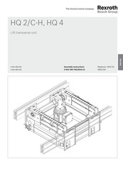
Bosch Rexroth HQ 2/C-H Assembly Instructions Manual (64 pages)
Brand:
Bosch
| Category:
Industrial Equipment
| Size: 13.62 MB
Table of Contents
Table of Contents
3
1 About this Documentation
5
Validity of Documentation
5
Required and Supplementary Documentation
5
Presentation of Information
5
Safety Instructions
5
Symbols
6
Designations
7
2 Safety Instructions
7
About this Section
7
Intended Use
7
Improper Use
7
Personnel Qualifi Cations
8
General Safety Instructions
8
Product-Specifi C Safety Instructions
8
Personal Protective Equipment
10
Operator's Obligations
10
3 General Notes Regarding Damage to Property and the Product
10
4 Scope of Delivery
11
Condition Upon Delivery
11
5 About this Product
11
Specifi Cations
11
Use of HQ 2/C-H or HQ 4 Lift Transverse Unit
11
HQ 2/C-H Lift Transverse Unit Features
11
Product Description
12
Identifi Cation of the Product
16
6 Transport and Storage
16
Transporting the Product
16
Storing the Product
16
7 Assembly
17
Unpacking
17
Installation Requirements
17
Installation Position
17
Fastening with T-Bolts
17
Required Tools
17
Symbols Used
18
Conversion to Motor Mounting M Left (by Customer)
19
Installing the Product
20
Preassembling the Mounting Bracket
20
Installing the Lift Transverse Unit
21
Preassembling the da 2
22
Installing the da 2
23
Installing the da 2
24
Installing the da 2
26
Installing the da 2/150-E Outfeeding Damper
27
Installing the VA 2/D-250 Slide Stop
28
Installing Lateral Guides
30
Installing the Position Monitoring Kit
32
Connecting the Product to the Pneumatic System
33
Making the Electrical Connection to the Product
35
8 Commissioning
37
Initial Start-Up
37
Residual Risks
38
Re-Commissioning after a Standstill Period
39
Adjusting Lifting Speed
39
9 Operation
40
Notes Regarding Operation
40
Wear
40
Measures to Reduce Wear
40
Loading the Workpiece Pallet
40
Environmental Infl Uences
41
10 Maintenance and Repair
42
Cleaning and Care
42
Inspection
43
Maintenance
43
LU 2 Automatic Lubrication Unit
44
Replacement of Wear Parts
45
Replacing the Motor
46
Replacing the Transmission, External Motor Mounting
47
Replacing the Transmission, Internal Motor Mounting
48
Replacing the Chain
51
Spare Parts
56
11 Decommissioning
56
12 Disassembly and Replacement
56
Preparing the Product for Storage/Later Use
56
13 Disposal
57
14 Upgrading and Modifi Cation
57
15 Troubleshooting and Repair
57
16 Technical Data
58
Ambient Conditions
58
Pneumatics
58
17 Appendix
59
Function Plans
59
Transfer to Transverse Section (TFE 3)
60
Transfer to Longitudinal Section (TFE 2)
61
Unloading from Longitudinal Conveyor (TFE 1)
62
Loading to Longitudinal Conveyor (TFE 4)
63
Advertisement
Related Products
Bosch Rexroth HQ 4
Bosch rexroth HQ 2/U-H
Bosch rexroth HQ 2/G-H
Bosch Rexroth HAB6-350-4X/2G07G-2N111-CE
Bosch Rexroth HAB10-330-4X/2G09G-2E111-CE
Bosch Rexroth HAB35-330-4X/2G09G-2E111-CE
Bosch Rexroth HAB50-330-4X/2G09G-2N111-CE
Bosch Rexroth HAB-4X Series
Bosch Rexroth HD 2/H
Bosch Rexroth HAD 2 Series
Bosch Categories
Dishwasher
Washer
Oven
Power Tool
Dryer
More Bosch Manuals
Login
Sign In
OR
Sign in with Facebook
Sign in with Google
Upload manual
Upload from disk
Upload from URL