Sign In
Upload
Manuals
Brands
ABB Manuals
Control Systems
ACSM1 Series
ABB ACSM1 Series Manuals
Manuals and User Guides for ABB ACSM1 Series. We have
10
ABB ACSM1 Series manuals available for free PDF download: Manual, Firmware Manual, Quick Start Up Manual, Hardware Manual, Quick Start Manual, User Manual, System Manual
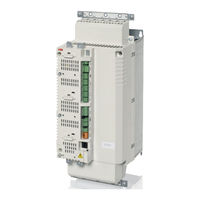
ABB ACSM1 Series Manual (510 pages)
Motion control system
Brand:
ABB
| Category:
Control Systems
| Size: 8.19 MB
Table of Contents
Table of Contents
5
Table of Contents
13
Introduction to the Manual
13
What this Chapter Contains
13
Compatibility
13
Safety Instructions
13
Reader
13
Contents
14
Product and Service Inquiries
14
Product Training
14
Providing Feedback on ABB Drives Manuals
14
Start-Up
15
What this Chapter Contains
15
How to Start up the Drive
15
How to Control the Drive through the I/O Interface
28
Drive Programming Using PC Tools
29
What this Chapter Contains
29
General
29
Programming Via Parameters
30
Application Programming
31
Function Blocks
31
User Parameters
31
Application Events
31
Program Execution
32
Application Program Licensing and Protection
32
Operation Modes
33
Drive Control and Features
35
What this Chapter Contains
35
Local Control Vs. External Control
35
Operating Modes of the Drive
36
Speed Control Mode
36
Torque Control Mode
36
Drive Control Chain for Speed and Torque Control
37
Position Control
38
Synchron Control
38
Homing Control
39
Profile Velocity Control
39
Drive Control Chain for Positioning
40
Motor Control Features
41
Scalar Motor Control
41
Autophasing
42
Flux Braking
44
Thermal Motor Protection
44
DC Voltage Control Features
47
Overvoltage Control
47
Undervoltage Control
47
Voltage Control and Trip Limits
47
Braking Chopper
48
Low Voltage Mode
48
Speed Control Features
50
Jogging
50
Speed Controller Tuning
51
Motor Feedback Features
54
Motor Encoder Gear Function
54
Mechanical Brake Control
55
Position/Synchron Control Features
59
Position Calculation
59
Position Estimation
60
Load Encoder Gear Function
61
Position Profile Generator
64
Dynamic Position Reference Limiter
66
Position Correction
68
Emergency Stop
82
Miscellaneous Features
83
Backup and Restore of Drive Contents
83
Drive-To-Drive Link
84
Fan Control Logic
85
Default Connections of the Control Unit
87
What this Chapter Contains
87
Parameters and Firmware Blocks
89
What this Chapter Contains
89
Types of Parameters
89
Firmware Blocks
90
Group 01 ACTUAL VALUES
91
Group 02 I/O VALUES
94
Group 03 CONTROL VALUES
94
Group 04 POS CTRL VALUES
101
Group 03 CONTROL VALUES
101
Group 06 DRIVE STATUS
103
Group 08 ALARMS & FAULTS
105
Group 06 DRIVE STATUS
105
Group 09 SYSTEM INFO
113
Group 08 ALARMS & FAULTS
113
Group 10 START/STOP
118
Group 09 SYSTEM INFO
118
Drive Logic
120
Group 10 START/STOP
120
11 Start/Stop Mode
126
12 Digital Io
129
Dio1
129
Dio2
129
Dio3
129
Group 13 ANALOGUE INPUTS
129
Group 12 DIGITAL IO
129
Ai1
133
Group 13 ANALOGUE INPUTS
133
Ai2
134
Group 15 ANALOGUE OUTPUTS
137
Ao1
137
Ao2
138
Group 16 SYSTEM
140
Group 17 PANEL DISPLAY
143
Group 20 LIMITS
145
Group 22 SPEED FEEDBACK
148
Speed Feedback
149
Group 24 SPEED REF MOD
154
Speed Ref Sel
155
Speed Ref Mod
156
Group 25 SPEED REF RAMP
158
Speed Ref Ramp
159
Group 26 SPEED ERROR
162
Speed Error
163
Group 28 SPEED CONTROL
167
Speed Control
168
Group 32 TORQUE REFERENCE
174
Torq Ref Sel
175
Torq Ref Mod
176
Group 33 SUPERVISION
178
Group 34 REFERENCE CTRL
182
Reference Ctrl
183
Group 35 MECH BRAKE CTRL
186
Group 40 MOTOR CONTROL
189
Group 45 MOT THERM PROT
192
Group 46 FAULT FUNCTIONS
196
Group 47 VOLTAGE CTRL
201
Group 48 BRAKE CHOPPER
203
Group 50 FIELDBUS
205
51 Fba Settings
209
Group 51 FBA SETTINGS
209
52 Fba Data in
211
Group 52 FBA DATA in
211
53 Fba Data out
212
Group 55 COMMUNICATION TOOL
212
Group 57 D2D COMMUNICATION
213
Group 55 COMMUNICATION TOOL
213
Group 60 POS FEEDBACK
214
Group 57 D2D COMMUNICATION
214
Group 60 POS FEEDBACK
218
Pos Feedback
219
Group 62 POS CORRECTION
223
Homing
223
Preset
225
Cyclic Correction
227
Group 65 PROFILE REFERENCE
233
Profile Ref Sel
234
Group 66 PROFILE GENERATOR
241
Profile Generator
242
Group 67 SYNC REF SEL
244
Group 68 SYNC REF MOD
247
Group 70 POS REF LIMIT
249
Pos Ref Lim
250
Group 71 POSITION CTRL
252
Pos Control
253
Group 90 ENC MODULE SEL
255
Encoder
256
Group 91 ABSOL ENC CONF
260
Group 92 RESOLVER CONF
266
Group 93 PULSE ENC CONF
267
Group 95 HW CONFIGURATION
270
Group 97 USER MOTOR PAR
271
Group 98 MOTOR CALC VALUES
274
Group 99 START-UP DATA
275
Advertisement
ABB ACSM1 Series Firmware Manual (448 pages)
Motion Control Program
Brand:
ABB
| Category:
Control Unit
| Size: 8.12 MB
Table of Contents
Table of Contents
5
Table of Contents
13
Introduction to the Manual
13
What this Chapter Contains
13
Compatibility
13
Safety Instructions
13
Reader
13
Contents
14
Product and Service Inquiries
14
Product Training
14
Providing Feedback on ABB Drives Manuals
14
Start-Up
15
What this Chapter Contains
15
How to Start up the Drive
15
How to Control the Drive through the I/O Interface
28
Drive Programming Using PC Tools
29
What this Chapter Contains
29
General
29
Programming Via Parameters
30
Application Programming
30
Function Blocks
31
Program Execution
31
Operation Modes
32
Drive Control and Features
33
What this Chapter Contains
33
Local Control Vs. External Control
33
Operating Modes of the Drive
34
Speed Control Mode
34
Torque Control Mode
34
Drive Control Chain for Speed and Torque Control
35
Position Control
36
Synchron Control
36
Homing Control
36
Profile Velocity Control
37
Drive Control Chain for Positioning
38
Special Control Modes
39
Motor Control Features
40
Scalar Motor Control
40
11.07 Autophasing
40
Thermal Motor Protection
41
DC Voltage Control Features
44
Overvoltage Control
44
Undervoltage Control
44
Voltage Control and Trip Limits
44
Braking Chopper
45
Speed Control Features
46
Jogging
46
Motor Feedback Features
48
Motor Encoder Gear Function
48
Mechanical Brake
49
Position/Synchron Control Features
52
Load Encoder Gear Function
52
Position Profile Generator
53
Dynamic Position Reference Limiter
55
Position Correction
56
Emergency Stop
71
Default Connections of the Control Unit
73
What this Chapter Contains
73
Parameters and Firmware Blocks
75
What this Chapter Contains
75
Types of Parameters
75
Firmware Blocks
76
Group 01 ACTUAL VALUES
77
Group 02 I/O VALUES
80
Group 03 CONTROL VALUES
80
Group 04 POS CTRL VALUES
87
Group 06 DRIVE STATUS
89
Group 08 ALARMS & FAULTS
91
Group 09 SYSTEM INFO
99
Group 10 START/STOP
101
Drive Logic
103
Group 11 START/STOP MODE
103
Group 12 DIGITAL IO
109
Dio1
112
Dio2
112
Dio3
112
Group 13 ANALOGUE INPUTS
112
Ai1
116
Ai2
117
15 Analogue Outputs
120
Ao1
120
Ao2
121
Group 16 SYSTEM
123
Group 17 PANEL DISPLAY
126
Group 20 LIMITS
127
Group 22 SPEED FEEDBACK
130
22 Speed Feedback
131
Group 24 SPEED REF MOD
134
Speed Ref Sel
135
Speed Ref Mod
136
Speed Ref Ramp
138
25 Speed Ref Ramp
139
Group 26 SPEED ERROR
142
26 Speed Error
143
Group 28 SPEED CONTROL
147
28 Speed Control
148
Group 32 TORQUE REFERENCE
153
Torq Ref Sel
153
Torq Ref Mod
154
Group 33 SUPERVISION
156
Group 34 REFERENCE CTRL
159
34 Reference Ctrl
160
Group 35 MECH BRAKE CTRL
163
Group 40 MOTOR CONTROL
166
Group 45 MOT THERM PROT
169
Group 46 FAULT FUNCTIONS
173
Group 47 VOLTAGE CTRL
176
Group 48 BRAKE CHOPPER
178
Group 50 FIELDBUS
180
Group 51 FBA SETTINGS
183
Group 52 FBA DATA in
185
Group 53 FBA DATA out
186
Group 57 D2D COMMUNICATION
187
Group 60 POS FEEDBACK
191
60 Pos Feedback
192
Group 62 POS CORRECTION
196
Homing
196
Preset
198
Cyclic Correction
199
65 Profile Reference
203
Profile Ref Sel
204
67 Sync Ref Sel
214
68 Sync Ref Mod
217
70 Pos Ref Limit
219
Pos Ref Lim
219
Position Ctrl
221
Pos Control
222
Encoder
225
91 Absol Enc Conf
229
92 Resolver Conf
234
93 Pulse Enc Conf
235
95 Hw Configuration
238
97 User Motor Par
239
98 Motor Calc Values
241
99 Start-Up Data
242
Parameter Data
247
What this Chapter Contains
247
Terms
247
Fieldbus Equivalent
248
Fieldbus Addresses
248
Pointer Parameter Format in Fieldbus Communication
248
32-Bit Integer Value Pointers
248
32-Bit Integer Bit Pointers
249
Actual Signals (Parameter Groups 1
250
Parameter Groups 10
253
ABB ACSM1 Series Firmware Manual (334 pages)
Speed and Torque Control Program
Brand:
ABB
| Category:
Servo Drives
| Size: 6.52 MB
Table of Contents
Table of Contents
5
Table of Contents
13
Introduction to the Manual
13
What this Chapter Contains
13
Compatibility
13
Safety Instructions
13
Reader
13
Contents
14
Product and Service Inquiries
14
Product Training
14
Providing Feedback on ABB Drives Manuals
14
Start-Up
15
What this Chapter Contains
15
How to Start up the Drive
15
How to Control the Drive through the I/O Interface
28
Drive Programming Using PC Tools
29
What this Chapter Contains
29
General
29
Programming Via Parameters
30
Application Programming
30
Function Blocks
31
Program Execution
31
Operation Modes
32
Drive Control and Features
33
What this Chapter Contains
33
Local Control Vs. External Control
33
Operating Modes of the Drive
34
Speed Control Mode
34
Torque Control Mode
34
Drive Control Chain for Speed and Torque Control
35
Special Control Modes
36
Motor Control Features
37
Scalar Motor Control
37
11.07 Autophasing
37
Thermal Motor Protection
38
DC Voltage Control Features
41
Overvoltage Control
41
Undervoltage Control
41
Voltage Control and Trip Limits
41
Braking Chopper
42
Speed Control Features
43
Jogging
43
Motor Feedback Features
45
Motor Encoder Gear Function
45
Mechanical Brake
46
Emergency Stop
50
Default Connections of the Control Unit
51
What this Chapter Contains
51
Parameters and Firmware Blocks
53
What this Chapter Contains
53
Types of Parameters
53
Firmware Blocks
54
Group 01 ACTUAL VALUES
55
Group 02 I/O VALUES
57
Group 03 CONTROL VALUES
57
Group 06 DRIVE STATUS
63
Group 08 ALARMS & FAULTS
65
Group 09 SYSTEM INFO
69
Group 10 START/STOP
71
Drive Logic
73
Group 11 START/STOP MODE
73
Group 12 DIGITAL IO
79
Dio1
82
Dio2
82
Dio3
82
Group 13 ANALOGUE INPUTS
82
Ai1
86
Ai2
87
Group 15 ANALOGUE OUTPUTS
90
Ao1
90
Ao2
91
Group 16 SYSTEM
93
Group 17 PANEL DISPLAY
96
Group 20 LIMITS
97
Group 22 SPEED FEEDBACK
99
22 Speed Feedback
100
Group 24 SPEED REF MOD
103
Speed Ref Sel
104
Speed Ref Mod
105
Speed Ref Ramp
107
25 Speed Ref Ramp
108
26 Speed Error
112
Group 28 SPEED CONTROL
116
28 Speed Control
117
Group 32 TORQUE REFERENCE
122
Torq Ref Sel
122
Torq Ref Mod
123
Group 33 SUPERVISION
125
Group 34 REFERENCE CTRL
128
34 Reference Ctrl
129
Group 35 MECH BRAKE CTRL
132
Group 40 MOTOR CONTROL
135
Group 45 MOT THERM PROT
138
Group 46 FAULT FUNCTIONS
142
Group 47 VOLTAGE CTRL
145
Group 48 BRAKE CHOPPER
147
Group 50 FIELDBUS
149
Group 51 FBA SETTINGS
152
Group 52 FBA DATA in
154
Group 53 FBA DATA out
155
Group 57 D2D COMMUNICATION
156
Group 90 ENC MODULE SEL
160
Encoder
161
Group 91 ABSOL ENC CONF
165
Group 92 RESOLVER CONF
170
Group 93 PULSE ENC CONF
171
Group 95 HW CONFIGURATION
174
Group 97 USER MOTOR PAR
175
Group 98 MOTOR CALC VALUES
177
Group 99 START-UP DATA
178
Parameter Data
183
What this Chapter Contains
183
Terms
183
Fieldbus Equivalent
184
Fieldbus Addresses
184
Pointer Parameter Format in Fieldbus Communication
184
32-Bit Integer Value Pointers
184
32-Bit Integer Bit Pointers
185
Actual Signals (Parameter Groups 1
186
Parameter Groups 10
189
Fault Tracing
199
What this Chapter Contains
199
Safety
199
Alarm and Fault Indications
199
How to Reset
199
Fault History
200
Alarm Messages Generated by the Drive
201
Fault Messages Generated by the Drive
208
Advertisement
ABB ACSM1 Series Firmware Manual (370 pages)
Motion Control Drives, Speed and Torque Control Program
Brand:
ABB
| Category:
DC Drives
| Size: 4.98 MB
Table of Contents
Table of Contents
5
Table of Contents
13
Introduction to the Manual
13
What this Chapter Contains
13
Compatibility
13
Safety Instructions
13
Reader
13
Contents
14
Product and Service Inquiries
14
Product Training
14
Providing Feedback on ABB Drives Manuals
14
Start-Up
15
What this Chapter Contains
15
How to Start up the Drive
15
How to Control the Drive through the I/O Interface
28
Drive Programming Using PC Tools
29
What this Chapter Contains
29
General
29
Programming Via Parameters
30
Application Programming
31
Function Blocks
31
User Parameters
31
Application Events
31
Program Execution
32
Application Program Licensing and Protection
32
Operation Modes
33
Drive Control and Features
35
What this Chapter Contains
35
Local Control Vs. External Control
35
Operating Modes of the Drive
36
Speed Control Mode
36
Torque Control Mode
36
Drive Control Chain for Speed and Torque Control
37
Motor Control Features
38
Scalar Motor Control
38
Autophasing
39
Flux Braking
41
Thermal Motor Protection
41
DC Voltage Control Features
44
Overvoltage Control
44
Undervoltage Control
44
Voltage Control and Trip Limits
44
Braking Chopper
45
Low Voltage Mode
45
Speed Control Features
47
Jogging
47
Speed Controller Tuning
48
Motor Feedback Features
51
Motor Encoder Gear Function
51
Mechanical Brake Control
52
Emergency Stop
55
Miscellaneous Features
57
Backup and Restore of Drive Contents
57
Drive-To-Drive Link
58
Fan Control Logic
59
Default Connections of the Control Unit
61
What this Chapter Contains
61
Parameters and Firmware Blocks
63
What this Chapter Contains
63
Types of Parameters
63
Firmware Blocks
64
Group 01 ACTUAL VALUES
65
Pos Feedback
66
Group 02 I/O VALUES
68
Group 03 CONTROL VALUES
68
Group 06 DRIVE STATUS
74
Group 03 CONTROL VALUES
74
Group 08 ALARMS & FAULTS
76
Group 06 DRIVE STATUS
76
Group 09 SYSTEM INFO
81
Group 08 ALARMS & FAULTS
81
Group 10 START/STOP
86
Group 09 SYSTEM INFO
86
Drive Logic
88
Group 11 START/STOP MODE
88
Group 10 START/STOP
88
Group 12 DIGITAL IO
94
Dio1
97
Dio2
97
Dio3
97
Group 13 ANALOGUE INPUTS
97
Group 12 DIGITAL IO
97
Ai1
101
Group 13 ANALOGUE INPUTS
101
Ai2
102
Group 15 ANALOGUE OUTPUTS
105
Ao1
105
Ao2
106
16 System
108
Group 17 PANEL DISPLAY
108
Group 16 SYSTEM
108
Group 20 LIMITS
111
Group 17 PANEL DISPLAY
111
Group 22 SPEED FEEDBACK
113
Group 20 LIMITS
113
Group 22 SPEED FEEDBACK
116
Speed Feedback
117
Group 24 SPEED REF MOD
122
Speed Ref Sel
123
Speed Ref Mod
124
Group 25 SPEED REF RAMP
126
Speed Ref Ramp
127
Group 26 SPEED ERROR
130
Speed Error
131
Group 28 SPEED CONTROL
134
Speed Control
135
Group 32 TORQUE REFERENCE
141
Torq Ref Sel
142
Torq Ref Mod
143
Group 33 SUPERVISION
145
Group 34 REFERENCE CTRL
149
Reference Ctrl
150
Group 35 MECH BRAKE CTRL
153
Group 40 MOTOR CONTROL
156
Group 45 MOT THERM PROT
159
Fault Functions
163
Voltage Ctrl
168
Brake Chopper
170
Fieldbus
172
Fba Settings
176
Fba Data in
178
Fba Data out
179
Communication Tool
180
D2D Communication
181
Enc Module Sel
185
Encoder
186
Absol Enc Conf
190
Resolver Conf
196
Group 93 PULSE ENC CONF
197
Group 95 HW CONFIGURATION
200
Group 97 USER MOTOR PAR
201
Group 98 MOTOR CALC VALUES
204
Group 99 START-UP DATA
205
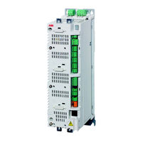
ABB ACSM1 Series Hardware Manual (112 pages)
ACSM1-04 Drive Modules
Brand:
ABB
| Category:
Control Unit
| Size: 7.11 MB
Table of Contents
Safety Instructions
5
What this Chapter Contains
5
Use of Warnings and Notes
5
Installation and Maintenance Work
6
Start-Up and Operation
8
Table of Contents
9
Table of Contents
14
Table of Contents
15
About this Manual
15
What this Chapter Contains
15
Compatibility
15
Intended Audience
15
Categorization According to the Frame Size
15
Categorization According to the + Code
15
Contents
16
Installation and Commissioning Flowchart
17
Inquiries
18
Terms and Abbreviations
19
The ACSM1-04
21
What this Chapter Contains
21
Layout (Frame a Shown)
21
Main Circuit and Control Interfaces
22
Operation
23
Type Code
23
Planning the Cabinet Assembly
25
What this Chapter Contains
25
Cabinet Construction
25
Disposition of the Devices
25
Grounding of Mounting Structures
25
Main Dimensions and Free Space Requirements
26
Cooling and Degrees of Protection
27
Preventing the Recirculation of Hot Air
29
Outside the Cabinet
29
Inside the Cabinet
29
Cabinet Heaters
29
Mechanical Installation
31
Contents of the Package
31
Delivery Check and Drive Module Identification
33
Before Installation
33
Requirements for the Installation Site
33
Installation Procedure
34
Direct Wall Mounting
34
DIN Rail Mounting (Frames a and B Only)
34
Cold Plate Mounting (ACSM1-04Cx-XXXX-X, Frames C and D Only)
35
Mains Choke Installation
35
Mains Filter Installation
36
Braking Resistor Installation
36
Planning the Electrical Installation
37
What this Chapter Contains
37
Motor Selection
37
Supply Connection
37
Supply Disconnecting Device
37
Europe
37
Other Regions
38
Thermal Overload and Short Circuit Protection
38
Thermal Overload Protection
38
Protection against Short-Circuit in Motor Cable
38
Protection against Short-Circuit in the Supply Cable or the Drive
38
Operating Time of the Fuses and Circuit Breakers
38
Circuit Breakers
38
Motor Thermal Protection
38
Ground Fault Protection
39
Emergency Stop Devices
39
Safe Torque off
40
Selecting the Power Cables
41
General Rules
41
Alternative Power Cable Types
41
Motor Cable Shield
42
Protecting the Relay Output Contacts and Attenuating Disturbances in Case of Inductive Loads
42
Residual Current Device (RCD) Compatibility
43
Selecting the Control Cables
44
Relay Cable
44
Control Panel Cable
44
Connection of a Motor Temperature Sensor to the Drive I/O
44
Routing the Cables
44
Control Cable Ducts
45
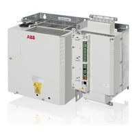
ABB ACSM1 Series Hardware Manual (102 pages)
Regen Supply Modules
Brand:
ABB
| Category:
Industrial Equipment
| Size: 11.08 MB
Table of Contents
Safety Instructions
5
What this Chapter Contains
5
Use of Warnings and Notes
5
Installation and Maintenance Work
6
Start-Up and Operation
8
Table of Contents
9
About this Manual
15
What this Chapter Contains
15
Compatibility
15
Intended Audience
15
Categorization According to the Frame Size
15
Categorization According to the + Code
15
Contents
16
Installation and Commissioning Flowchart
17
Inquiries
18
Terms and Abbreviations
19
The ACSM1-204
21
What this Chapter Contains
21
Layout (Frame a Shown)
22
WFU-XX Regen Filter Module
23
Main Circuit and Control Interfaces
25
Operation
26
Type Code
26
Planning the Cabinet Assembly
27
What this Chapter Contains
27
Cabinet Construction
27
Disposition of the Devices
27
Grounding of Mounting Structures
27
Free Space Requirements
28
Cooling and Degrees of Protection
28
Preventing the Recirculation of Hot Air
30
Outside the Cabinet
30
Inside the Cabinet
30
Cabinet Heaters
30
Mechanical Installation
31
Contents of the Package
31
Delivery Check and Regen Supply Module Identification
33
Before Installation
33
Requirements for the Installation Site
33
Installation Procedure
34
Direct Wall Mounting of the Regen Supply Module
34
DIN Rail Mounting (Frames a and B Only) of the Regen Supply Module
34
Cold Plate Mounting (ACSM1-204Cx-XXXX-X, Frames C and D Only)
35
Installation of the WFU-XX Regen Filter Module
36
Braking Resistor Installation
36
Planning the Electrical Installation
37
What this Chapter Contains
37
Compatibility
37
ACSM1-04 Drives
37
Other Drive Types
37
Checking the Charging Capacity
38
Single AC Input
38
Supply Connection
39
Main Contactor
39
Supply Disconnecting Device
40
Europe
40
Other Regions
40
Thermal Overload and Short Circuit Protection
40
Thermal Overload Protection
40
Protection against Short-Circuit in the Supply Cable or the Regen Supply Module
40
Operating Time of the Fuses and Circuit Breakers
40
Circuit Breakers
41
Protection against Short-Circuit in the DC Cable
41
Protection of the WFU-XX Regen Filter Module against Thermal Overload
41
Ground Fault Protection
41
Emergency Stop Devices
41
Selecting the Power Cables
42
General Rules
42
Power Cable Shield
42
Power Cables Cross-Section
43
Protecting the Relay Output Contacts and Attenuating Disturbances in Case of Inductive Loads
43
Selecting the Control Cables
45
Relay Cable
45
Control Panel Cable
45
Routing the Cables
45
Control Cable Ducts
46
Electrical Installation
47
What this Chapter Contains
47
Checking the Insulation of the Assembly
47
Regen Supply Module and WFU-XX Regen Filter Module
47
Supply Cable
47
Braking Resistor Assembly
47
Power and Control Cable Connection
48
Power and Control Cable Connection Diagram
48
Procedure
49
Installation of Power Cable Clamp Plates
50
Power Cable Connection - Frame Size a
51
Power Cable Connection - Frame Size B
52
ABB ACSM1 Series Quick Start Up Manual (139 pages)
function blocks for Siemens PLC’s
Brand:
ABB
| Category:
Controller
| Size: 6.42 MB
Table of Contents
Table of Contents
4
List of Related Manuals
8
Introduction
8
Contents of this Chapter
8
Compatibility
8
Target Audience
9
Safety Instructions
9
Purpose of the Manual
9
Limitations
9
Contents of the Manual
10
Related Documents
10
SIMATIC Manager/Tia Portal with ABB Drives and PROFIBUS Module Setup
10
Cybersecurity Disclaimer
11
Disclaimer
11
Drive Configuration
12
Contents of this Chapter
12
Overview
12
Configuring ACS355 Drives
13
Starting ACS355 Drives for PROFIBUS DP
13
ACS355 Minimum Required Parameter Settings for PROFIBUS DP
13
Starting ACS355 Drives for PROFINET
14
ACS355 Minimum Required Parameter Settings for PROFINET
15
ACS355 more Parameters Read from Drive to PLC (Optional)
15
ACS355 more Parameters Written from PLC to Drive (Optional)
16
Configuring ACS380 Drives
16
Starting ACS380 Drives for PROFIBUS DP
16
ACS380 Minimum Required Parameter Settings PROFIBUS DS
17
Starting ACS380 Drives for PROFINET
18
ACS380 Minimum Required Parameter Settings for PROFINET
18
ACS380 more Parameters Read from Drive to PLC (Optional)
19
ACS380 more Parameters Written from PLC to Drive (Optional)
19
Configuring ACS550 Drives
20
Starting ACS550 Drives for PROFIBUS DP
20
ACS550 Minimum Required Parameter Settings for PROFIBUS DP
20
Starting ACS550 Drives for PROFINET
21
ACS550 Minimum Required Parameter Settings for PROFINET
21
ACS550 more Actual Values or Parameters to be Read from Drive to PLC (Optional)
22
ACS550 more Parameters to be Written from PLC to Drive (Optional)
22
Configuring ACS580 Drives
23
Starting ACS580 Drives for PROFIBUS DP
23
ACS580 Minimum Required Parameter Settings for PROFIBUS DP
24
Starting ACS580 Drives for PROFINET
25
ACS580 Minimum Required Parameter Settings for PROFINET
26
ACS580 more Parameters Read from Drive to PLC (Optional)
27
ACS580 more Parameters Written from PLC to Drive (Optional)
27
Configuring ACS800 Drives
27
Starting ACS800 Drives for PROFIBUS DP
27
ACS800 Minimum Required Parameter Settings for PROFIBUS DP
28
Starting ACS800 Drives for PROFINET
29
ACS800 Minimum Required Parameter Settings for PROFINET
30
ACS800 more Parameters Read from Drive to PLC (Optional)
31
ACS800 more Parameters Written from PLC to Drive (Optional)
31
Configuring ACS850 Drives
31
Starting ACS850 Drives for PROFIBUS DP
31
ACS850 Minimum Required Parameter Settings for PROFIBUS DP
32
Starting ACS850 Drives for PROFINET
32
ACS850 Minimum Required Parameter Settings for PROFINET
33
ACS850 more Parameters Read from Drive to PLC
34
ACS850 more Parameters Written from PLC to Drive
34
Configuring ACS880 Drives
34
Starting ACS880 Drives for PROFIBUS DP
34
ACS880 Minimum Required Parameter Settings for PROFIBUS DP
35
Starting ACS880 Drives for PROFINET
36
ACS880 Minimum Required Parameter Settings for PROFINET
37
ACS880 more Parameters Read from Drive to PLC (Optional)
37
ACS880 more Parameters Written from PLC to Drive (Optional)
38
Configuring ACSM1 Drives
38
Starting ACSM1 Drives for PROFIBUS DP
38
ACSM1 Minimum Required Parameter Settings for PROFIBUS DP
39
Starting ACSM1 Drives for PROFINET
40
ACSM1 Minimum Required Parameter Settings for PROFINET
41
ACSM1 more Parameters Read from Drive to PLC (Optional)
42
ACSM1 more Parameters Written from PLC to Drive (Optional)
42
ABB ACSM1 Series User Manual (46 pages)
Brand:
ABB
| Category:
Control Panel
| Size: 1.11 MB
Table of Contents
Table of Contents
5
About the Manual
7
What this Chapter Contains
7
Compatibility
7
Safety
7
Intended Audience
7
Product and Service Inquiries
7
Product Training
7
Providing Feedback on ABB Drives Manuals
7
Hardware Description
9
What this Chapter Contains
9
About Control Panels
9
Compatibility
9
ACSM1 Control Panel
10
Features
10
Overview
10
Maintenance
10
Status Line
11
Installation
13
What this Chapter Contains
13
Connecting the Panel to the Drive
13
The Cable
13
Mounting the Control Panel
14
Mounting Template
15
Gasket
16
Operation
17
What this Chapter Contains
17
Basics of Operation
17
List of Tasks
18
Help and Panel Version - any Mode
19
How to Get Help
19
How to Find out the Panel Version
19
Basic Operations - any Mode
20
How to Start, Stop and Switch between Local and Remote Control
20
Output Mode
21
How to Change the Direction of the Motor Rotation
21
How to Select the Monitored Signals
22
How to Set the Speed, Frequency, Torque or Position Reference in the Output Mode
23
How to Adjust the Display Contrast
23
Parameters
24
How to Select a Parameter and Change Its Value
24
How to Change the Value of Value Pointer Parameters
25
How to Change the Value of Bit Pointer Parameter to Point to the Value of a Bit in Another Signal
27
How to Change the Value of Bit Pointer Parameter to Fixed 0 (FALSE) or 1 (TRUE)
29
Fault Logger
31
How to View Faults
31
How to Reset Faults
31
Time & Date
32
How to Show or Hide the Clock, Change Display Formats, Set the Date and Time and Enable or Disable Clock Transitions According to the Daylight Saving Changes
32
Parameter Backup
34
ABB ACSM1 Series System Manual (34 pages)
System Engineering Manual
Brand:
ABB
| Category:
Servo Drives
| Size: 0.61 MB
Table of Contents
Safety Instructions
5
Table of Contents
6
About this Manual
8
Compatibility
8
Intended Audience
8
Categorization According to the Frame Size
8
ACSM1-04 Drive Module and Options Documentation
8
Common DC Configurations
9
Introduction
9
Configuration Steps
10
ACSM1 Power Ratings for DC Connection
11
Power Requirements
12
DC Link Power P
12
DC,Mot of Motoring Axis
12
DC,Gen of Regenerating Axis
12
Average Motoring Power P
13
Mot,Ave
13
Peak Motoring Power P
13
Average Regenerative Power P Mot,Max
13
Gen,Ave
13
Gen,Max
13
Supply Unit Selection
14
DC Link Power Supplied Via ACSM1
14
Single AC Input
14
Multiple AC Input
14
Checking the Charging Capacity
15
Single AC Input
15
Multiple AC Input
16
Charging Current
16
External DC Supply
17
Mains Choke Selection
18
Mains Choke Data
18
Single AC Input
19
Multiple AC Input
19
Harmonic Distortion
20
Regenerative Power
21
Common DC Capacitance
21
ACSM1 DC Link Capacitance
22
Energy Capacity in Common DC
22
Resistor Braking
24
ACSM1 Braking Power Ratings
24
Single Braking Chopper
25
Multiple Braking Choppers
25
Braking Resistor Selection
26
Single Braking Resistor
26
Multiple Braking Resistors
27
Braking Resistor Types
27
General System Design Items
28
Fuse Protection
28
Selection of AC Supply Fuses
28
Selection of DC Connection Fuses
29
ABB ACSM1 Series Quick Start Manual (48 pages)
PLC and drives integration using Modbus RTU
Brand:
ABB
| Category:
Controller
| Size: 2.6 MB
Table of Contents
Table of Contents
2
Introduction
4
Safety Instructions
4
Limitations
4
Fieldbus Grounding
6
Fieldbus Shield
6
End Termination
6
Pull Up/Pull down Resistors
6
Drives with Embedded Fieldbus
7
Fieldbus Modules for ABB Drives
8
Common Recommendations
8
ABB Cable TK505
9
AC500 COM1 - Master at the Bus Line End
11
AC500 COM2 - Master at the Bus Line End
11
AC500-Eco COM1 - Master at the Bus Line End
11
AC500-Eco COM2 - Master at the Bus Line End
12
Drive Configuration
13
Starting up ACS310 Drives with Embedded Modbus RTU
14
Starting up ACS355 Drives with FMBA-01 Modbus RTU Adapter
15
Starting up ACS800 Drives with RMBA-01 Modbus RTU Adapter
17
Starting up ACS850, ACQ810 Drives with Embedded Modbus RTU
18
Starting up ACS880 Drives with FSCA-01 Modbus RTU Adapter
19
Starting up ACSM1 Drives with FSCA-01 Modbus RTU Adapter
20
Install Drives Library
21
Control Builder Plus for PLC and Drives
22
Hardware Configuration
22
IP Configuration of CPU (for Ethernet Connection between PC and PLC)
24
Codesys
25
CODESYS Tabs
25
Library Manager
26
PLC Logic
27
Download Program to PLC
32
Create Boot Project
33
Test the Program
34
Read and Write more Data between PLC and Drive (Optional)
36
Visualizations
43
Add more Drives (Optional)
46
Actualization Rate
47
Other Useful Documentation
47
Revision
47
Advertisement
Related Products
ABB ACS800-02
ABB ACS800-U2
ABB Advant AC500
ABB ACSM1-04 Series
ABB ACSM1-04Lx
ABB ACSM1-204
ABB ACS800-37LC-0580-3
ABB ACS800-U1-00U1-2
ABB ACS880-07C-0363A-3
ABB ACS880-01-061A-2
ABB Categories
Industrial Equipment
Controller
Measuring Instruments
Battery Charger
DC Drives
More ABB Manuals
Login
Sign In
OR
Sign in with Facebook
Sign in with Google
Upload manual
Upload from disk
Upload from URL