Sign In
Upload
Manuals
Brands
Ricoh Manuals
Copier
MP C6004 series
Ricoh MP C6004 series Manuals
Manuals and User Guides for Ricoh MP C6004 series. We have
3
Ricoh MP C6004 series manuals available for free PDF download: Field Service Manual, User Manual, Read This First Manual
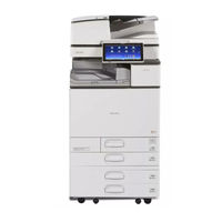
Ricoh MP C6004 series Field Service Manual (2155 pages)
Brand:
Ricoh
| Category:
All in One Printer
| Size: 43.09 MB
Table of Contents
Important Safety Notices
3
Safety Information
3
Prevention of Physical Injury
4
Health Safety Conditions
5
Observance of Electrical Safety Standards
5
Safety and Ecological Notes for Disposal
5
Handling the Development Unit Cooling System
6
Handling Toner
6
Laser Safety
7
Safety Instructions for the Color Controller
8
Symbols, Abbreviations and Trademarks
9
Symbols, Abbreviations
9
Trademarks
10
Table of Contents
13
1 Product Information
45
Product Overview
45
Component Layout
45
Paper Path
47
Drive Layout
50
Machine Codes and Peripherals Configuration
52
Main Machine
52
Asia/Pacific/ Central, South America)
54
Korea)
54
Option
55
Europe)
55
Diagram
59
MP C3004/C3504 Peripherals
59
MP C4504/C5504/C6004 Peripherals
61
Diagram
61
Specifications
63
Installation Requirements
65
Environment
65
Machine Level
66
Machine Space Requirements
66
Machine Dimensions
67
Model -27, -29, -65 (220-240 V)
69
Power Requirements
70
Input Voltage Level
70
Model -17, -18 (120-127 V)
70
Main Machine Installation
71
Important Notice on Security Issues
71
Overview
71
Password Setting Procedure
72
Installation Flow Chart
75
Accessory Check
76
Installation Procedure
78
Removal of Packing Materials and Shipping Retainers
78
For Machines with Preinstalled SPDF: Removal of Protective Sheet
84
Removal of PCDU Seals: Overview
85
Removal of PCDU Seals: MP C4504/C5504/C6004
86
Removal of PCDU Seals: MP C3004/C3504
89
Attaching the Optical Cloth Pocket
91
Attaching the Paper Exit Tray Parts
91
Installing the Feeler for the Paper Exit Full Sensor
92
Checking the Position of the Paper Exit Feeler
92
Attaching the Decals
93
For Machines with Preinstalled ARDF: Fax Stamp Installation (Option)
95
Toner Bottle Installation and Toner Initialization
96
Enabling the Copy Data Security Function
98
Image Quality Test / Settings
99
Loading Paper
99
ACC Execution and Color Registration Adjustment
99
Before Test
99
Paper Settings
102
Auto Remote Firmware Update Settings
102
Checking the Copy Image with the Test Chart
102
Pre-Operation Set up and Checks
103
Configuration Procedure
103
Checking the ARFU Connection
106
Security Function Settings
107
Checking the Result from the Firmware Update Setting
107
Checking the Result Using the Logging Data
107
Settings Relevant to the Service Contract
108
Moving the Machine
109
Cautions Upon Lashing
111
Anti-Condensation Heater (Scanner, PCDU)
113
Accessory Check
113
Installation Procedure
114
Anti-Condensation Heater (PCDU)
125
Accessory Check
125
Installation Procedure
126
Anti-Condensation Heater for Paper Feed Trays
136
Accessory Check
136
Connecting to Main Machine Tray
137
Connecting to Paper Feed Unit PB3160
141
Connecting to Paper Feed Unit PB3150
143
Connecting to LCIT PB3170/ PB3230
146
Paper Feed Unit PB3160 (D693)
149
Accessory Check
149
Installation Procedure
149
Paper Feed Unit PB3150 (D694)
155
Accessory Check
155
Installation Procedure
155
Lcit Pb3170/Pb3230 (D695)
160
Accessory Check
160
Installation Procedure
160
Changing the Paper Size
164
Lcit Rt3030 (D696)
167
Accessory Check
167
Installation Procedure
168
Changing the Paper Size
175
Modification for Increasing the LCIT Capacity
176
List of Parts to be Attached
176
Replacement Procedure
178
Caster Table Type M3 (D178)
186
Accessory Check
186
Installation Procedure
186
How to Place the MFP on the Caster Table
187
How to Place the Paper Feed Unit PB3150 on the Caster Table
188
Platen Cover PN2000 (D700)
189
Accessory Check
189
Installation Procedure
189
Ardf Df3090 (D779)
192
Accessory Check
192
Installation Procedure
192
When Feeding Thin Paper
197
Spdf Df3100 (D3B0)
198
Accessory Check
198
Attaching the SPDF
199
Installation Procedure
199
Adjust SP Settings
208
Bin Tray BN3110 (D3CQ)
211
Accessory Check
211
Installation Procedure
212
Checking the Position of the Paper Exit Feeler
218
Internal Shift Tray SH3070 (D691)
220
Accessory Check
220
Installation Procedure
220
Checking the Position of the Paper Exit Feeler
224
Side Tray Type M3 (D725)
226
Accessory Check
226
Installation Procedure
227
Bridge Unit BU3070 (D685)
234
Accessory Check
234
Installation Procedure
234
Booklet Finisher SR3240 (D3Bb)/Finisher SR3230 (D3BA)
242
Accessory Check
242
Installation Procedure
243
Attaching the Proof Support Tray
251
Punch Unit PU3060 (D706)
253
Accessory Check
253
Installation Procedure
254
Booklet Finisher SR3220 (D3B9)
268
Accessory Check
268
Installation Procedure
269
Attaching the Proof Support Tray
275
Finisher SR3210 (D3B8)
277
Accessory Check
277
Installation Procedure
278
Attaching the Proof Support Tray
286
Stapleless Stapler Initial Settings
287
How to Change the Setting of Staple Method for Stapleless Stapler
288
How to Set Margin Erase for Stapleless Stapler
288
Punch Unit PU3050
290
Accessory Check
290
Installation Procedure
291
Internal Finisher SR3130 (D690)
304
Accessory Check
304
Installation Procedure
305
Punch Unit PU3040 (D716)
319
Accessory Check
319
Installation Procedure
320
Internal Finisher SR3180 (D766)
327
Accessory Check
327
Installation Procedure
328
Stapleless Stapler Initial Settings
344
How to Change the Setting of Staple Method for Stapleless Stapler
344
How to Set Margin Erase for Stapleless Stapler
345
Banner Paper Guide Tray Type M19 (D3BF)
346
Accessory Check
346
Installation Procedure
346
Imageable Area Extension Unit Type M19 (D3BR-07)
351
Accessory Check
351
Installation Procedure
351
When You Forgot to Change the SP
353
External Keyboard Bracket Type M19 (D3BR-10)
355
Accessory Check
355
Installation Procedure
355
Internal Options
361
List of Slots
361
Mp C4504/C5504/C6004
361
Mp C3004/C3504
362
USB Device Server Option Type M19 (D3BC-28,-29)
363
Component Check
363
Interface Board Surface
364
Installation Procedure
365
What Do the LED Indications Mean
370
Notes for Energy Save Mode Setting
370
IP Address Setting
370
Extended USB Board Type M19 (D3BS-01)
373
Component Check
373
Installation Procedure
373
IEEE 1284 Interface Board Type M19 (D3C0)
375
Accessories
375
Installation Procedure
375
IEEE 802.11Agn Interface Unit Type M19 (D3BR-01)
377
Accessory Check
377
Attaching the Boards
378
Installation Procedure
378
Attaching the Antenna
379
User Tool Settings for IEEE 802.11A/G/N
380
SP Mode Settings for IEEE 802.11 Wireless LAN
381
File Format Converter Type M19 (D3BR-04)
383
Accessory Check
383
Installation Procedure
383
Bluetooth Interface Unit Type D (D566-01)
385
Accessory Check
385
Installation Procedure
385
Memory Unit Type M19 4GB
387
Accessory Check
387
Installation Procedure
387
Enhanced Security HDD Option Type M12 (D3A6-02)
390
Accessory Check
390
Installation Procedure
390
After Installing the HDD
394
Optional Counter Interface Unit Type M12 (B870-21)
396
Accessory Check
396
Installation Procedure
397
Key Counter Bracket Type M3 (D739-09)
400
Accessory Check
400
Installation Procedure
400
Card Reader Bracket Type 3352 (D593-61)
406
Component Check
406
Installation Procedure
407
NFC Card Reader Type M19 (D3BS-21)
411
Accessory Check
411
Installation Procedure
412
Smart Card Reader Built-In Unit Type M19 (D3BS-22)
419
Accessory Check
419
Installation Procedure
419
Procedure for Connecting to the Main Machine USB Slot
420
Procedure for Connecting to the Operation Panel USB Slot
426
SD Card Options
433
SD Card Slots
433
List of Slots Used
433
SD Card Appli Move
435
Overview
435
Move Exec
437
Undo Exec
439
Postscript3 Unit Type M19 (D3BD-05, -06, -07)
441
Accessories
441
Installation Procedure
441
Camera Direct Print Card Type M19 (D3BD-13)
444
Accessories
444
Installation Procedure
444
IPDS Unit Type M20 (D3BC-20, -21, -22)
446
Accessories
446
Installation Procedure
446
XPS Direct Print Option Type M19 (D3BC-24, -25, -26)
449
Accessories
449
Installation Procedure
449
OCR Unit Type M13 (D3AC-23, -24, -25)
451
Searchable PDF Function Outline
451
Accessory Check
451
Installation Procedure
451
Recovery Procedure
454
Dataoverwritesecurity Unit Type M19 (D3BS-03)
455
Overview
455
Component List
455
Before You Begin the Procedure
456
Seal Check and Removal
456
Installation Procedure
457
Configuring "Auto Erase Memory" (Performed by the Customer)
460
Remote Settings
463
Security Settings
469
Security Function Installation
469
Data Overwrite Security
470
Before You Begin the Procedure
470
Installation Procedure
470
Using Auto Erase Memory
471
HDD Encryption
473
Before You Begin the Procedure
473
Enable Encryption Setting
474
Installation Procedure
474
Check the Encryption Settings
477
Backing up the Encryption Key
479
Encryption Key Restoration
480
3 Preventive Maintenance
485
PM Parts Settings
485
Replacement Procedure of the PM Parts
485
Method 1: by SP3701
485
Method 2: by [PM Counter / New Unit Set] Menu
487
After Installing the New PM Parts
488
SP Descriptions
489
Preparation before Operation Check
489
SP Descriptions
490
Operation Check
490
PM Parts List
491
4 Replacement and Adjustment
493
Notes on the Main Power Switch
493
Push Switch
493
Characteristics of the Push Switch (DC Switch)
493
Shutdown Method
494
Forced Shutdown
495
Beforehand
496
Special Tools
497
Exterior Covers
498
Front and Rear Side Covers
498
Overview
498
Right and Left Side Covers
499
Paper Exit Covers
500
Inner Covers
500
Front Cover
501
Controller Cover
502
Upper Left Cover
502
Left Rear Cover
503
Left Cover
504
Rear Cover
507
Rear Lower Cover
508
Right Rear Cover
508
Right Upper Cover
509
Proximity Sensor Cover
509
Proximity Sensor
511
Main Power Switch Cover
512
Waste Toner Cover
513
Inverter Tray
514
Paper Exit Tray
515
Paper Exit Lower Cover
515
Paper Exit Front Cover
516
Inner Upper Cover
517
Inner Lower Cover
517
Smart Operation Panel
519
Operation Panel Unit
519
USB Cable
522
ADF Removal
525
Scanner Unit
528
Before You Begin
528
Scanner Exterior
528
Scanner Front Cover
528
Scanner Right Cover
529
Scanner Left Cover
529
Scanner Upper Cover
530
Exposure Glass
530
Scanner Carriage
532
Cleaning the Scanner Carriage Mirror
536
Scanner Motor
539
Original Size Sensor
541
Scanner HP Sensor
541
Ardf/Platen Cover Sensor
542
Scanner FFC
543
When Changing the FFC
544
Laser Unit
548
Before Replacement
549
Removing
549
Installing a New Laser Unit
550
Adjustment after Replacing the Laser Unit
551
Polygon Mirror Motor
552
Adjustment after Replacing the Polygon Mirror Motor
553
SP Descriptions
553
Notes When Replacing a PCDU
555
Mp C3004/C3504/C4504
555
Mp C5504/C6004
555
Attaching the Springs
558
Adjustment before Replacing the PCDU
561
Replacement
562
Adjustment after Replacing the PCDU
565
Pcu/Development Unit
565
Before Replacing a PCU or Development Unit
565
Replacement
566
Precautions When Joining the PCU and the Development Unit
569
Adjustment after Replacing the PCU And/Or the Development Unit
570
Imaging Temperature Sensor (Thermistor)
571
Check Procedure after Replacing
571
Waste Toner
573
Replacement
573
Image Transfer Unit
574
What to Do before Replacing the Image Transfer Belt
575
Image Transfer Cleaning Unit
578
What to Do before Replacing the Image Transfer Cleaning Unit
579
Replacement
580
Image Transfer Belt
583
Attaching the Belt
586
Adjustment after Replacing the Image Transfer Belt
590
Paper Transfer Roller
591
Paper Transfer Roller Unit
595
Fusing Entrance Sensor
597
TM/ID Sensor
598
Replacement Procedure
600
Adjustment after Replacing the TM/ID Sensor
602
Temperature and Humidity Sensor
604
ITB Contact and Release Sensor
606
Image Transfer Lock Unit
606
Installing the Image Transfer Lock Unit
608
Drive Unit Overview
611
Paper Feed Motor
612
Transport Motor
612
Paper Transfer Contact and Release Motor Unit
613
Imaging Drive Unit
614
PCU Motor: CMY
616
Development Motor: CMY
617
Development Motor: Black
618
PCU: Black / Image Transfer Motor
619
Registration Motor
620
Fusing Motor
620
Paper Exit / Pressure Release Motor
621
Duplex Entrance Motor
621
Toner Transport Motor
622
Sub Hopper
623
Toner End Sensor
627
Toner Bottle Drive Motor
628
ID Chip
630
Fusing Unit
633
Fusing Entrance Guide Plate
634
Cleaning the Fusing Entrance Guide Plate
634
Fusing Exit Guide Plate
635
Cleaning the Fusing Exit Guide Plate
636
Fusing Upper Cover
636
Fusing Lower Cover
637
Heating Sleeve Unit
638
How to Cancel SC544-02/SC554-02 with a New Unit Detection Fuse
642
Pressure Roller
643
Adjustment before Replacing the Pressure Roller
643
Replacement
643
Thermostat Unit
645
Non-Contact Thermistor
646
Pressure Roller Thermistor
646
Thermopile Unit
647
Pressure Roller HP Sensor
647
Fusing Shield Position Sensor (MP C4504/5504/6004)
648
Fusing Shield Drive Motor (MP C4504/5504/6004)
649
Fusing Exit Solenoid
650
Paper Exit Switching Solenoid
652
Paper Exit Sensor
653
Reverse Sensor
655
Paper Exit Full Sensor
656
Reverse Motor
657
Fusing Exit Sensor
658
1St Paper Feed Unit
660
2Nd Paper Feed Unit
662
Paper Dust Collection Unit
664
Pick-Up Roller, Paper Feed Roller, Separation Roller, Torque Limiter
664
1St Tray Lift Motor/ 2Nd Tray Lift Motor
667
Paper Feed Sensor
668
Transport Sensor
669
Limit Sensor
670
Paper End Sensor
670
Registration Sensor
671
Bypass Tray Unit
673
Bypass Paper End Sensor
676
Bypass Pick-Up Roller
677
Bypass Paper Feed Roller
678
Bypass Separation Roller/Torque Limiter
678
Bypass Width Sensor
679
Bypass Length Sensor
683
Duplex Unit
684
Duplex/By-Pass Motor
685
Duplex Entrance Sensor
686
Duplex Exit Sensor
688
Electrical Components
690
Printed Circuits Behind the Controller Box
691
Printed Circuit/Parts Inside the Power Box
692
Controller Box Cover
693
Ipu
693
Bcu
694
Replacing the NVRAM (EEPROM) on the BCU
695
When Installing the New BCU
695
Controller Board
697
Replacing the Nvrams on the Controller Board
699
Hdd
706
Imaging IOB
707
Adjustment after Replacement
707
Hvp_Tts
709
PSU (AC Controller Board)
709
PSU (DC Power)
710
Paper Transport IOB
712
Hvp-Cb
713
HVP-CB with Bracket
714
Proximity Sensor Board
716
Fans/Filters
717
Adjustment before Replacing the Dust Filter
717
Ozone Filter/Dust Filter
717
Deodorization Filter
718
Development Intake Fan
719
Ozone Exhaust Fan
720
Fusing Exhaust Fan
721
Drive Cooling Fan (MP C4504/5504/6004)
722
Main Exhaust Fan (MP C4504/5504/6004)
723
Toner Supply Cooling Fan
723
PSU Cooling Fan
724
PSU Exhaust Fan (MP C4504/5504/6004)
725
Controller Box Cooling Fan
726
Image Adjustment
727
Auto Color Calibration
727
Scanning
728
Scanner Leading Edge and Side-To-Side Registration
729
Scanner Sub-Scan Magnification
729
Ardf
730
ARDF Side-To-Side, Leading Edge Registration and Trailing Edge
730
ARDF Sub-Scan Magnification
731
Image Area
731
Leading Edge
731
Registration
731
Adjustment Standard
732
Erase Margin Adjustment
732
Paper Registration Standard
732
Adjusting the Tone of the Printed Image
733
Opening the Printer Driver's "Color Balance Details" Window
734
Adjustment by Changing the Printer Driver Setting
734
PCL6 Universal Driver / PS Universal Driver
735
Color Balance Details Window
737
Adjusting the Tone in the "Color Balance Details" Window
738
Adjustment Examples
740
Adjustment by Changing the Machine's Profile Setting
742
Procedure to Change the Profile Setting
742
Patterns and Tendency of the Tone for each Profile
743
Printer Gamma Correction
744
Color Registration
748
Check the Occurrence of Color Registration Errors
748
Judgment for Type of Color Registration Error
748
5 System Maintenance
759
Service Program Mode
759
Entering SP Mode
759
Exiting SP Mode
760
Types of SP Modes
760
SP Mode Button Summary
761
Switching between SP Mode and Copy Mode for Test Printing
762
Selecting the Program Number
762
Service Mode Lock/Unlock
763
Remarks
764
Others
764
SP Tables
766
Firmware Update (SD Card)
767
Firmware Type
767
Overview
767
What Is Included in the Firmware Package
769
Procedure
769
Preparation
770
Update Procedure
770
Error Screens During Updating
775
Firmware Update (Remote Firmware Update)
781
RFU Performable Condition
781
Firmware Update (Smart Firmware Update)
782
Overview
782
Immediate Update
783
Update at the Next Visit (Reserve)
786
How to Set the Machine to Download Firmware Later (Reserve)
786
How to Check if the Firmware Downloaded with Reserve
788
How to Install Firmware Downloaded with Reserve
790
Update Via SD Card
793
Firmware Update (Auto Remote Firmware Update)
796
Overview
796
Downloading and Updating Process
797
Downloads the Latest Package
798
Judgement of ARFU
798
Update Process
800
Related SP
803
Updating Javavm
807
Creating an SD Card for Updating
807
Updating Procedure
807
List of Error Messages
808
NVRAM Data Upload/Download
810
Uploading Content of NVRAM to an SD Card
810
Downloading an SD Card to NVRAM
811
Address Book Upload/Download
813
Information List
813
Upload
815
Capturing the Device Logs
816
Overview
816
Security of the Operation Log
818
Retrieving the Device Logs Via Operation Panel
818
Procedure for Retrieving the Device Log with SD Card
818
Retrieving the Device Logs Via Web Image Monitor
821
SMC List Card Save Function
825
Overview
825
Procedure
825
File Names of the Saved SMC Lists
827
Error Messages
828
UP/SP Data Import/Export
829
Data that Can be Imported and Exported
829
Data that Cannot be Imported or Exported
829
Exporting Device Information
830
Importing Device Information
831
SP Data Import/Export
832
Data that Can be Imported and Exported
832
Exporting Device Information
833
Importing Device Information
834
Possible Solutions for Import/Export Problems
835
Card Save Function
838
Overview
838
Procedure
838
Error Messages
841
6 Troubleshooting
843
Self-Diagnostic Mode
843
SC Automatic Reboot
843
Controller Self-Diagnosis Outline
846
Controller Self-Diagnosis Flowchart
847
HDD-Related Message
850
Service Call Conditions
852
Summary
852
SC Logging
853
List of Automatic Reboot Target SC
853
Engine SC
853
Controller SC
862
SC Code Classification
865
Service Call 101-195
866
SC100 (Engine: Scanning)
866
Service Call 202-285
878
SC200 (Engine: Image Writing)
878
Service Call 312-396
886
SC300 (Engine: Charge, Development)
886
Service Call 441-498
895
SC400 (Engine: Around the Drum)
895
Service Call 501-584
901
SC500 (Engine: Paper Transport 1: Paper Feed, Duplex, Transport)
901
SC500 (Engine: Fusing)
922
Heating Sleeve (Center) Error (SC54*-**)
922
Heating Sleeve (Edge) Error (SC55*-**)
932
Pressure Roller Thermistor (Center) Error (SC56*-**)
937
Pressure Roller Thermistor (Edge) Error (SC57*-**)
940
Pressure Roller Thermistor (Full-Bleed Edge) Error (SC58*-**)
942
SC620-Service Call 620-689
945
SC600 (Engine: Communication and Others)
945
SC600 (Controller)
966
Service Call 700-792
978
SC700 (Engine: Peripherals)
978
Service Call 816-899
1012
SC800 (Controller)
1012
Service Call 900-998
1054
SC900 (Engine: Others)
1054
SC900 (Controller)
1056
Troubleshooting for SC Errors
1061
When SC285-02 (MUSIC Error) Is Displayed
1061
Cause
1061
Solution
1062
When SC370 (TM (ID) Sensor Calibration Error) Is Displayed
1064
Cause
1064
Countermeasure (5): TM/ID Sensor Shutter Defective
1064
Countermeasure (6): Paper Transfer Contact/Release Mechanism Defective
1064
Countermeasure (7): Skew Motor in Laser Unit Error
1064
Solution
1064
Adjustment after Recovery
1065
Recovery Check Procedure
1065
When SC501, SC502, SC503, or SC504 (Paper Tray Error) Is Displayed
1066
Solution
1066
When SC549 (Shield Operation Error Detection) Is Displayed
1068
Troubleshooting Flowchart
1068
Fusing Shield Check
1068
Solution
1072
Isolation Diagram of SC663, 664, 665, 667, 668, and 670-01
1073
When SC670 (Engine Start up Error) Is Displayed
1074
Cause
1074
Solution
1074
When SC672 (Controller Start up Error) Is Displayed
1075
Symptom
1075
Cause
1076
Solution
1076
[A]: Leds on the Controller Board
1078
[B]: Abnormal Mode: Leds on the Controller Board
1079
[C]: Reconnecting and Replacing the USB Cable
1080
[D]: Replacing the Memory
1082
[E]: CMOS Clear
1083
[F]: Fuse on the IPU
1084
[G]: Replacing the USB Cable and the Operation Panel
1084
Jam Detection
1091
Jam Display
1091
Clearing a Paper Jam
1091
Paper Jam History
1092
History Checking Method
1092
Paper Jam Display
1092
Jam Codes and Display Codes
1092
Paper Size Code
1105
Sensor Locations
1106
Troubleshooting for Transport/Paper Feeding of the Machine
1107
Curled Paper
1107
Initial Jam
1107
Initial Jam: Cause Code 001 / Location Code B
1108
Initial Jam: Cause Code 001 / Location Code C
1109
Initial Jam: Cause Code 001 / Location Code Z
1110
Tray 1 no Feeding: Late Jam : Cause Code 003
1111
Tray 2 no Feeding: Late Jam : Cause Code 004
1114
Tray 1 Transport Sensor: Late Jam : Cause Code 011
1116
Tray 2 Transport Sensor : Late Jam : Cause Code 012
1118
Registration Sensor : Late Jam : Cause Code 017
1120
Paper Exit Sensor : Late Jam : Cause Code 020
1121
Tray 1 Transport Sensor : Lag Jam : Cause Code 051
1122
Tray 2 Transport Sensor: Lag Jam: Cause Code 052
1125
Registration Sensor: Lag Jam: Cause Code 057
1126
Paper Exit Sensor: Lag Jam: Cause Code 060
1128
Reverse Sensor: Late Jam: Cause Code 024
1129
Reverse Sensor: Lag Jam : Cause Code 064
1130
Duplex Exit Sensor: Late Jam: Cause Code 025
1131
Duplex Exit Sensor: Lag Jam: Cause Code 065
1132
Duplex Entrance Sensor: Late Jam: Cause Code 027
1133
Duplex Entrance Sensor: Lag Jam: Cause Code 067
1135
Display Error
1136
"No Paper in Tray 1" Is Displayed Even When the Paper Is in
1136
No Paper in Tray 2" Is Displayed Even When the Paper Is in
1137
"Tray 2 Not Set" Is Displayed Even When the Tray Is Set
1138
Tray 1 Not Set" Is Displayed Even When the Tray Is Set
1138
Does Not Shift to Right Door Open Status
1139
Wrong Paper Size Displayed on the Operation Panel
1139
Cannot Detect Paper Full
1140
Cannot Print as Paper Full Alert Cannot be Turned off
1141
Waste Toner Bottle Is Never Full
1142
Others
1142
Replace the Waste Toner Bottle" Is Displayed Even When It Is Clear that the Waste Toner Bottle Is Not Full
1142
Waste Toner Bottle Is Not Detected Even When It Is Set
1143
Paper Transfer Unit Open/Close LED Not Lit & Paper Transfer Unit Open
1143
No Waste Toner Bottle Set Is Displayed on Controller Board Even When It Is Clear that Is Set
1143
Paper Transfer Unit Open/Close LED Not Lit
1144
Paper Transfer Unit Open/Close LED Always Lit
1144
Troubleshooting for Finishing Options
1146
Finisher Registration Adjustment
1146
For Booklet Finisher SR3240 (D3BB) / Finisher SR3230 (D3BA)
1146
If the Paper Shifts Towards the Front
1147
If the Paper Shifts Towards the Rear
1147
For Booklet Finisher SR3220 (D3B9) / Finisher SR3210 (D3B8)
1148
Finisher Jogger Problem (for Booklet Finisher SR3220 (D3B9) / Finisher SR3210 (D3B8))
1150
Early Tray Full Detection Mylar for Internal Finisher SR3130 (D690)
1151
Pasting the Mylar
1151
Paper Curl Problem for SR3180 (D766)
1155
Specifications: Maximum Sheet Capability for Staple Jobs
1158
Maximum Number of Sheets for Stapling and What Happens When the Job Has too Many
1158
Behavior: When the Number of Sheets Exceeds the Maximum Staple Capability
1159
Select the Behavior When the Job Has more than the Maximum of Staple Capability with SP5199
1160
Electrical Component Defects
1161
Fuses
1161
Vertical Streaks on Copies Due to Scanning Problems
1165
Overview
1165
Converting the ARDF DF3090 to Contact Scanning
1166
Converting the SPDF3100 to Contact Scanning
1169
Image Quality Problems
1173
Misjudgment for Auto Color Selection (Copy/Scanner)
1173
Error Condition
1173
Cause
1173
Countermeasure
1174
When an Abnormal Image Is Generated
1176
7 Detailed Descriptions
1179
Guidance for those Who Are Familiar with Predecessor Products
1179
Changes from the Previous Machine
1179
Scanner
1179
Image Processing
1180
Process Control
1180
PCDU (Photo Conductor and Development Unit)
1181
Toner Supply
1181
Waste Toner
1181
Image Transfer and Paper Transfer
1182
Feed / Transport Part
1182
Fusing
1183
Electrical Parts
1183
Exterior Cover/Air Flows (Fan Control)
1184
Drive Part
1185
Others
1185
Binding Margin Setting
1186
Advertisement
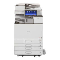
Ricoh MP C6004 series User Manual (264 pages)
Brand:
Ricoh
| Category:
All in One Printer
| Size: 13.92 MB
Table of Contents
User Guide
1
Table of Contents
3
How to Read the Manuals
9
Symbols Used in the Manuals
9
Model-Specific Information
10
Names of Major Features
11
1 What You Can Do with this Machine
13
Searching by What You Want to Do
13
Reducing My Costs
13
Using Scanned Files on the Computer
14
Registering Destinations
15
Operating the Machine more Effectively
16
What You Can Do with this Machine
17
Customizing the [Home] Screen
17
Customizing Home Screen
17
Making Copies Using Various Functions
18
Printing Data Using Various Functions
19
Utilizing Stored Document
20
Sending and Receiving Faxes Without Paper
20
Sending and Receiving Faxes Via the Internet
22
Sending and Receiving Faxes by Using the Machine Without Fax Unit Installed
23
Using the Facsimile and the Scanner in a Network Environment
24
Embedding Text Information in Scanned Files
24
Preventing Information Leakage (Security Functions)
25
Centrally Controlling Scan Conditions and Distribution
26
Monitoring and Setting the Machine Using a Computer
26
Preventing Unauthorized Copying
27
2 Getting Started
29
Guide to Names and Functions of Components
29
Guide to Components (Mainly Europe)
29
Guide to Components (Mainly Asia)
32
Guide to Components (Mainly North America)
36
Guide to Functions of the Machine's Options
40
Guide to Functions of the Machine's External Options
40
Guide to the Names and Functions of the Machine's Control Panel
59
Changing the Display Language
60
How to Use the [Home] Screen
61
Possible Operations on the Standard Application Screen
63
Adding Icons to the [Home] Screen
64
How to Use each Application
67
[Copy] Screen
68
[Fax] Screen
70
[Scanner] Screen
75
Registering Functions in a Program
80
Turning On/Off the Power
83
Turning on the Main Power
83
Turning off the Main Power
83
Logging in the Machine
85
When the Authentication Screen Is Displayed
85
User Code Authentication Using the Control Panel
85
Logging in Using the Control Panel
85
Logging out Using the Control Panel
86
Placing Originals
87
Placing Originals on the Exposure Glass (Mainly Europe)
87
Placing Originals on the Exposure Glass (Mainly Asia)
87
Placing Originals on the Exposure Glass (Mainly North America)
88
Placing Originals in the Auto Document Feeder (Mainly Europe and Asia)
89
Placing Originals in the Auto Document Feeder (Mainly North America)
90
3 Copy
93
Basic Procedure
93
Auto Reduce / Enlarge
94
Duplex Copying
96
Specifying the Original and Copy Orientation
97
Combined Copying
99
One-Sided Combine
100
Two-Sided Combine
101
Copying Onto Custom Size Paper
103
Copying Onto Envelopes
104
Sort
106
Changing the Number of Sets
107
Storing Data in the Document Server
109
4 Fax
111
Basic Procedure for Transmissions (Memory Transmission)
111
Registering a Fax Destination
111
Deleting a Fax Destination
113
Transmitting While Checking Connection to Destination (Immediate Transmission)
114
Canceling a Transmission
115
Canceling a Transmission before the Original Is Scanned
115
Canceling a Transmission While the Original Is Being Scanned
115
Canceling a Transmission after the Original Is Scanned
115
Storing a Document
117
Sending Stored Documents
118
Printing the Journal Manually
120
5 Print
121
Quick Install
121
Displaying the Printer Driver Properties
122
Standard Printing
123
When Using the PCL 6 Printer Driver
123
Printing on both Sides of Sheets
124
When Using the PCL 6 Printer Driver
124
Types of Two-Sided Printing
124
Combining Multiple Pages into Single Page
125
When Using the PCL 6 Printer Driver
125
Types of Combine Printing
125
Printing on Envelopes
127
Configuring Envelope Settings Using the Control Panel
127
Printing on Envelopes Using the Printer Driver
127
Saving and Printing Using the Document Server
128
Storing Documents in Document Server
128
Managing Documents Stored in Document Server
129
Using the Quick Print Release Function
130
Using the Print/Scan(Memory Storage Device) Function
131
6 Scan
135
Basic Procedure When Using Scan to Folder
135
Creating a Shared Folder on a Computer Running Windows/Confirming a Computer's Information
135
Registering an SMB Folder
137
Deleting an SMB Registered Folder
140
Entering the Path to the Destination Manually
141
Basic Procedure for Sending Scan Files by E-Mail
142
Registering an E-Mail Destination
142
Deleting an E-Mail Destination
144
Entering an E-Mail Address Manually
144
Basic Procedure for Storing Scan Files
145
Checking a Stored File Selected from the List
146
Specifying the File Type
147
Specifying Scan Settings
148
7 Document Server
149
Storing Data
149
Printing Stored Documents
151
8 Web Image Monitor
153
Displaying Top Page
153
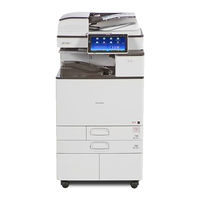
Ricoh MP C6004 series Read This First Manual (36 pages)
Brand:
Ricoh
| Category:
Copier
| Size: 1.7 MB
Table of Contents
Table of Contents
3
How to Read the Manuals
4
Symbols Used in the Manuals
4
Disclaimer
4
Notes
5
Machine Types
5
1 Manuals Provided with this Machine
7
Manuals for this Machine
7
How to Use the Operating Instructions
9
Read HTML Manuals
9
Read the HTML Manuals on the Control Panel
10
2 Safety Information for this Machine
11
Safety Symbols for this Machine
11
Safety Information
12
Safety During Operation
12
Safety Precautions to be Followed
12
Safety Labels of this Machine
19
Positions of WARNING and CAUTION Labels
19
Paper Trays
20
Symbols for Earth, Insulation, and Power Switch
23
3 Other Information for this Machine
25
Laws and Regulations
25
Duplication and Printing Prohibited
25
Laser Safety
25
Notes to USA Users of FCC Requirements
26
Important Safety Instructions for Facsimile Unit
29
Notes to Canadian Users of Wireless Devices
29
Notes to Canadian Users of Facsimile Unit
30
Recycling Batteries (for Users in the USA and Canada)
31
4 Appendix
33
Trademarks
33
Advertisement
Advertisement
Related Products
Ricoh Aficio MP C3002
Ricoh Aficio MP C4502A
Ricoh Aficio MP C5502A
Ricoh MP C2504 series
Ricoh MP C4504 series
Ricoh MPC 2050
Ricoh MP C401SP
Ricoh Aficio MP C2530
Ricoh MP CW2201
Ricoh MP C3504 series
Ricoh Categories
All in One Printer
Printer
Digital Camera
Copier
Printer Accessories
More Ricoh Manuals
Login
Sign In
OR
Sign in with Facebook
Sign in with Google
Upload manual
Upload from disk
Upload from URL