Sign In
Upload
Manuals
Brands
Nordson Manuals
Melting Machines
ProBlue Flex
Nordson ProBlue Flex Manuals
Manuals and User Guides for Nordson ProBlue Flex. We have
3
Nordson ProBlue Flex manuals available for free PDF download: Product Manual, Manual, User Manual
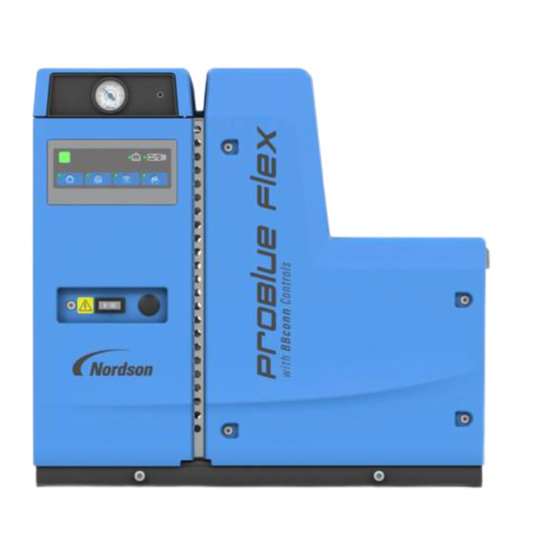
Nordson ProBlue Flex Product Manual (418 pages)
Adhesive Melter with BBconn Controls
Brand:
Nordson
| Category:
Melting Machines
| Size: 12.91 MB
Table of Contents
Table of Contents
3
Safety
15
Safety Alert Symbols
15
Responsibilities of the Equipment Owner
16
Safety Information
16
Instructions, Requirements, and Standards
16
User Qualifications
17
Applicable Industry Safety Practices
17
Intended Use of the Equipment
17
Instructions and Safety Messages
18
Installation Practices
18
Operating Practices
18
Maintenance and Repair Practices
19
Equipment Safety Information
19
Equipment Shutdown
20
Relieving System Hydraulic Pressure
20
De-Energizing the System
20
Disabling the Applicators
20
General Safety Warnings and Cautions
21
Other Safety Precautions
24
First Aid
24
Safety Labels and Tags
25
Description
27
Key Components
28
Melter User Interface
29
Product Description
30
Intended Use
31
Limitations of Use
31
Electromagnetic Compatibility (EMC)
31
Residual Risks
32
Experience of Installation Personnel
32
Theory of Operation
33
Functional Blocks
34
Low Voltage Controller (LVC)
34
Power Distribution and Control
35
DC Power Supply
35
Temperature Control Modules
35
User Interface(S)
36
Adhesive Level Sensor
36
Optional Functional Blocks
36
How the Blocks Operate as a System
37
Melter Configuration Codes
38
Melter Identification
39
Other Sources of Information
40
Installation Guide
40
User Interface Quick Reference Guide
40
Problue Flex Manuals and Service Kit Instruction Sheets
40
Installation
41
Overview
41
Quick-Start
42
Additional Information
42
Experience of Installation Personnel
42
Melter Installation
43
Installation Tasks
43
Installation Requirements
44
Melter Clearances
44
Ventilation
46
Electrical Power
46
Compressed Air
47
Melter Mounting Considerations
48
Unpack the Melter
49
Contents of the Installation Kit
49
Customer-Supplied Materials
50
Mount the Melter
50
Removing the Melter from the Sub-Base
51
Mounting the Melter
55
Connecting Incoming Power
56
Configure the Electrical Service
57
Melter Power Requirements
57
Kg Tank (T04, X04)
57
Kg and 10 Kg Tank (T07, X07, T10, X10)
58
Kg/Hr MOD (M07, Z07)
58
Kg/Hr MOD (M14, Z14)
59
Kg Tank (T15, X15)
59
Kg/Hr MOD (M21, Z21)
60
Connecting Power Cables
61
Connect a Pump Control Signal
65
Connecting Power to the Solenoid Valve
66
Single Acting Pump Operation Notes
67
Connect a Compressed Air Supply
68
Connect Hoses and Applicators
71
Connecting the Hoses
71
Connecting the Applicators
74
Set up the Melter
75
Using the OLED User Interface
75
Set up the Melter Inputs and Outputs (I/O)
76
I/O Connections
76
Input Parameters
77
Output Parameters
78
Install Optional Accessories
80
Basic Melter Operation
81
Operator Level Tasks
81
Additional Information
81
Melter Operation
82
Filling the Melter Tank
82
Starting the Melter for the First Time
84
OLED User Interface
85
Commissioning Setup Wizard
85
Describing the Home Screen
87
Navigation Controls
88
Master Controls
90
System LED Indicators
91
System Status Chart
92
Toggle Switch
93
Shutting down the Melter
94
Maintenance
95
Relieving System Pressure
96
Locking out External Communications
97
Cleaning the Melter
97
Servicing the Pump
98
Supplies
98
Lubricating the Pump
99
Service Kit
99
Replacing the Filter
99
Draining the Tank
100
Cleaning the Tank
102
Troubleshooting
103
About this Section
103
Safety
103
Troubleshooting Checklist
104
Overview
104
AC Power
104
DC Power
104
Level
104
Fill
105
Lid Switch
105
Temperature Control
105
Pump, Pneumatics and Pressure Control
106
User Interface
106
Standard I/O
106
Usb
107
Clock/Scheduler
107
Communications
107
Remote Color Touchscreen (if Used)
107
Software
107
Melters with 480V Transformer Base
108
Other Options, Accessories, Upgrades, Future Product Enhancements
108
400/480 Volt Melters
108
About Built-In Diagnostics
109
About Nordnet
110
Troubleshooting Nordnet
110
Electrical Box - Internal Board Connections
111
Identifying Electrical Components
112
Melter Pneumatic Flow Control
118
Pressure Control and Pump Compatibility
119
Troubleshoot the Melter
122
Checking the Melt or Manifold RTD
122
Checking the Operation of the Thermostats
122
Removing the Level Sensor, Melt RTD, or Melt Thermostat
123
Remove Melter Panels
123
Access the Components
124
Removing the Manifold RTD
126
Checking the Operation of the Power Relay
126
Checking the Operation of the Tank, Grid, or Manifold TRIAC
127
Checking the Resistance of the Tank, Grid, and Manifold Heaters
127
Troubleshoot the Fill System
131
Fill Time Limit
131
Fill System Troubleshooting Table
132
Calibrating the Level Sensor
133
Cleaning Adhesive bin Blockage
133
Technical Data
135
General Specifications
135
Pump Specifications
136
Melter Specifications
137
4, 7, 10 Kg Tank Melters
137
And 14 Kg MOD Melters
137
A and B Chassis for 240V and 480V Melters
137
Electrical Specifications
138
Melter Power Requirements
138
Kg Tank (T04, X04)
138
Kg and 10 Kg Tank (T07, X07, T10, X10)
139
Kg/Hr MOD (M07, Z07)
139
Kg/Hr MOD (M14, Z14)
140
Kg Tank (T15, X15)
140
Kg/Hr MOD (M21, Z21)
141
Discrete I/O
141
Standard Remote Input/Output
141
Communication
142
Pressure Management
142
Fill System Specifications
143
Melter Dimensions
144
Melter Sub-Base Dimensions
147
Wiring Diagram - Electrical Box Enclosure Layout
148
Wiring Diagram - Input Power
149
Wiring Diagram - Power Distribution
150
Wiring Diagram - Power Distribution Expansion Board
151
Wiring Diagram - Low Voltage Control Board
152
Wiring Diagram - Melt and Manifold (Melt on Demand)
155
Wiring Diagram - Hoses and Applicators
156
Wiring Diagram - 4 Channel Power Module #2
158
Wiring Diagram - TB3 Variations
159
Wiring Diagram - Light Tower
160
Wiring Diagram - Legacy Inputs/Outputs
161
Wiring Diagram - Chassis Ground
162
Wiring Diagram - Hose/Applicator Expansion Base
163
Wiring Diagram - Hose/Applicator Ground Tree
164
Wiring Diagram - Hose/Applicator Expansion Power Module #3
165
Wiring Diagram - Hose/Applicator Expansion Power Module #4
166
Wiring Diagram - Adhesive Tracking Board
167
Parts
169
Using the Illustrated Parts Lists
169
Problue Flex Melter Assembly
170
Melt on Demand Melter
184
Additional Tank Components
187
Manifold Modules
188
Filter Manifold for Double Acting Pumps
192
Filter Manifold for Single Acting Pumps
194
Hose Manifold
196
Pump Parts
197
Manifold Heater Module
198
Heater Plate Parts
200
Lid Module
202
Fill Lid Module
204
Electrical Cabinet Assembly
206
Blank Hose/Applicator Module
209
4/6 Channel Hose/Applicator Module
209
OLED Electrical Enclosure Door
210
OEM Electrical Enclosure Door
211
Heater Harness
212
Standard Double Acting Regulator
213
Double Acting Regulator with Transducer
214
Standard Double Acting Remote Run up Regulator
215
P1 Single Acting Pneumatic Panel Assembly Service Kit
216
P2 Single Acting Pneumatic Panel Assembly Service Kit
216
Standard Single Acting Regulator Module with Gauge
217
Standard Single Acting Regulator Module with Transducer
218
Lid Switch Module
219
Lid Switch Replacement Parts
220
Enclosure Module
222
Kg/7 MOD/14 MOD Enclosure Module
222
Electrical Cables and Fuses
226
Ship-With Kit
228
Service Kits
229
E-Box Enclosure Service Kits
229
Assorted Jumper Harness Pack Kit
229
OLED Electrical Door Service Kit
229
OEM Electrical Door Service Kit
229
E-Box Knockout Service Kit
229
E-Box Full Replacement Service Kit
230
LVC Replacement Service Kit
230
Power Supply Service Kit
230
Power Distribution Replacement Service Kit
230
4-Channel Hose/Applicator Module Service Kit
231
Temperature Control Module Service Kit
231
4-Channel Hose/Applicator Blank Service Kit
231
Power Distribution Expansion Service Kit
231
15 Amp Fuse Service Kit
232
Pump Service Kits
233
Pump Replacement Service Kit
233
Pump Service Kit
233
High Output Double Acting Pump Replacement Service Kit
234
High Output Double Acting Pump Service Kit
235
Single Acting High Output Pump Replacement Service Kit
235
Single Acting High Output Pump Service Kit
236
Low Viscosity Pump Replacement Service Kit
236
Low Viscosity Pump Service Kit
237
Low Pressure Pump Replacement Service Kit
237
Low Pressure Pump Service Kit
238
Low Pressure/Low Viscosity Pump Replacement Service Kit
238
Low Pressure Low Viscosity Pump Service Kit
239
Magnetic Actuator Service Kit
240
Air Valve Assembly Service Kit
240
Magnetic Fork Service Kit
240
Airline Service Kit
240
Pump and PDV Fittings Service Kit
241
Single Acting Airline , P1 and P2 Service Kit
241
Lid Service Kits
241
Lid Switch Service Kit
241
Fill Lid Filter Service Kit
241
FF Inlet Tube Service Kit
242
Size a Replacement Lid Service Kit
242
Size B Replacement Lid Service Kit
242
Size a Fill Lid Replacement Service Kit
242
Size B Fill Lid Replacement Service Kit
243
Tank Service Kits
243
4/7Kg and 7/14 Kg/Hr MOD Level Sensor Service Kit
243
10 Kg Level Sensor Service Kit
243
Kg 230V Tank Service Kit
244
Kg 400/480V Tank Service Kit
245
Grid/Hopper Service Kits
246
MOD 7 Kg, 700W, 230V Grid/Hopper Service Kit
246
MOD 14 Kg, 1200W, 230V Grid/Hopper Service Kit
246
MOD 7 Kg, 700W, 400/480V Grid/Hopper Service Kit
247
MOD 14 Kg, 1200W, 400/480V Grid/Hopper Service Kit
247
Manifold Service Kits
248
Standard Hose Manifold Service Kit
248
Manifold Filter Service Kit
248
Manifold Center Service Kit
248
Single Acting Pump Manifold Filter Service Kit
249
Heater Service Kits
249
480V, 2500W Heater Block Service Kit
249
480V, 1000W Heater Block Service Kit
250
Enclosure Service Kits
251
Mounting Plate (Sub-Base) Service Kit
251
Kg Tank and 7/14 MOD
251
Mounting Plate (Sub-Base) Service Kit, 7/10 Kg Tank
251
Insulation Service Kits
252
Kg Tank Insulation Service Kit
252
MOD Insulation Service Kit
252
Manifold Insulation Service Kits
253
Standard Manifold Kit Guard Service Kit
253
Manifold Insulation Service Kit
253
MOD Manifold Insulation Service Kit
253
Upgrade Kits
254
Fill Upgrade Kit, Size a
254
Fill Upgrade Kit, Size B
254
To 6 H/A Expansion Kit
255
To 4 H/A Expansion Kit
255
Legacy I/O Kit
256
External USB Kit
256
Size a Tank Lock Kit
256
Size B Tank Lock Kit
257
MOD 14, 1200W, 400/480V Kit
257
MOD 7, 700W, 400/480V Kit
257
MOD 14, 1200W, 200/240V Kit
257
MOD 7, 700W, 200/240V Kit
258
App Module Upgrade Kit
258
Pneumatic Assembly P2 Upgrade Kit
258
Pneumatic Assembly P3 Upgrade Kit
259
Spare Parts List
260
Basic Spare Parts Service Kit
260
Basic Expanded Spare Parts Service Kit
260
Pneumatic Filter Service Kit
260
Pneumatic Filter and Bulkhead Bracket Service Kit
261
Flex RTD Replacement Service Kit
261
Pneumatic Transducer Service Kit
261
Drain Chute Replacement Service Kit
261
Drain Valve Replacement Service Kit
262
Wireway Cover Service Kit
262
P4/P7/P10 Pressure Discharge Valve Service Kit
262
100 Mesh Saturn Filter Service Kit
262
Pneumatic Panel Assembly Service Kit
263
P2 Pneumatic Panel Assembly Service Kit
263
P3 Pneumatic Panel Assembly Service Kit
263
Thermostat Service Kit
263
Single Acting P1 Pneumatic Assembly Service Kit
264
Single Acting P2 Pneumatic Assembly Service Kit
264
General Parts
265
Problue Flex Common Hardware
265
Problue Flex Jumper Pack, 3/PE, 200/240V
266
Problue Flex Jumper Pack, 3/N/PE, 200/400V
266
Problue Flex Jumper Pack, 1/N/PE, 200/240V, 25
266
Problue Flex Jumper Pack, 3/PE, 200/240V, 10
266
Problue Flex Jumper Pack, 1/PE, 200/240V, 10
266
Problue Flex Assorted Jumper Pack
267
Hydraulics Fittings,90 Degree
267
Hydraulics Fittings, 90 Degree, 25
267
Hydraulics Fittings, 45 Degree
267
Hydraulics Fittings, 45 Degree, 25
267
Hydraulics Fittings Straight, 10
268
Hydraulics Fittings Straight
268
Calculating Melter Power Requirements
269
Appendix A
269
Appendix B
273
Appendix B SP Pump Diagnostics and Repair
273
Introduction
273
Available Pump Options
273
Pump Function
274
Double Acting Pump
274
Pump Isolation Valve
275
Pressure Discharge Valve
275
Single Acting Pump
275
Pump Diagnostics
276
Double Acting Pump Diagnostics
276
Single Acting Pump Diagnostics
278
Pump Disassembly and Reassembly
280
Melter Preparation
280
Required Tools and Materials
280
Tools
280
Service Parts
281
Supplies
281
Remove the Pump from the Melter (All Pumps
282
Remove the Actuator Assembly (Double Acting Pumps Only
285
Remove the Magnetic Actuator Assembly (Double Acting Pumps Only
285
Remove the Air Valve Assembly (Double Acting Pumps Only
286
Special Reassembly Instructions
286
Remove the Shifter Fork (Double Acting Pumps Only
287
Special Reassembly Instructions
287
Remove the Cylinder Head and Cylinder (All Pumps
287
Remove the Piston Cups (All Pumps
288
Special Reassembly Instructions
288
Remove the Siphon Check Valve Assembly and Hydraulic Piston Assembly (All Pumps
288
Remove the Pressure Check Valve for Double Acting Pumps
289
Special Reassembly Instructions
289
Remove the Pressure Check Valve for Single Acting Pumps
289
Replace the Hydraulic Piston Seal (All Pumps
290
Installing the Pump (All Pumps
291
Standard Double Acting Pump Assembly Parts List
292
High Output Double Acting Pump Assembly Parts List
294
Low Viscosity Double Acting Pump Assembly Parts List
296
Low Pressure Double Acting Pump Assembly Parts List
298
Low Pressure/Low Viscosity Double Acting Pump Assembly Parts List
300
High Output Single Acting Pump Assembly Parts List
302
Actuator Assembly Parts List
304
Piston Assembly Hydraulics Parts List
306
High Output Double Acting Hydraulic Piston Assembly
307
Low Viscosity Double Acting Hydraulic Piston Assembly
308
Appendix C the Bbconn Cloud
309
Web Address
309
List of Browsers
309
Key Functions
309
Importing and Exporting Files
310
Appendix D
311
Appendix D Adhesive Tracking System
311
Overview
311
Intended Use
312
Unintended Use
312
Theory of Operation
313
Technical Data
315
Specifications
315
Useful Calculations and Conversion Formulas
316
Specific Gravity Calculation
316
K-Factor Calculation
316
Conversions
317
I/O Declarations on the ATS Board
318
Flow Meter Assembly Parts Lists
320
Flow Meter and Sensor Parts
320
Flow Meter Parts
322
ATS Service Kits
324
ATS Upgrade Kit
324
ATS Hose Manifold Kit
324
ATS PCA Kit
325
Inductive Sensor Cable Kit
325
ATS Manifold Guard Kit
325
ATS Service Kit
326
Appendix E Optional Accessories
327
Available Accessories
327
Air Pressure Relief Valve
328
Air Pressure Relief Valve Kit
328
Wi-Fi Module
329
Wi-Fi Module Service Kit
329
Light Tower
330
Light Tower Board and Light Tower Service Kit
331
Light Tower Board Only Service Kit
331
Communication Cards
332
Profibus Communication Service Kit
332
Ethercat Communication Service Kit
332
CC Link Communication Service Kit
332
Devicenet Communication Service Kit
333
Powerlink Communication Service Kit
333
CC Link IE Communication Service Kit
333
Remote Touchscreen User Interface
334
PB Touchscreen Service Kit (Comes with 5M Communication Harness
334
5 M Communication Cable
335
10 M Communication Cable
335
Remote Touchscreen T50 Service Kit
335
Fulfill System
336
Dimensions
336
Adhesive Storage bin Dimensions
337
Fulfill System Specifications
339
Single-Feed Adhesive Storage bin
340
Multi-Feed Adhesive Storage bin
342
Sequencer
344
Adhesive Transfer Hose Parts
348
Adhesive bin Pump Parts
350
Suction Lance Kit
352
Transfer Hose Solenoid Harnesses
354
Quick Disconnect Kits (Optional
355
Service Kits
356
Field Install Kits
356
Appendix F
357
Appendix F Problue Flex 400/480 Volt Transformer
357
Overview
357
Intended Use
358
Unintended Use
358
Transformer Function
358
Installation
359
Installation Tasks
359
Transformer Sizing
360
Clearances
362
Ship-With Kit Components
364
Preparing the Transformer for Installation
365
Mounting the Transformer on the Parent Machine
367
Connecting Electrical Service to the Transformer
368
Preparing the 400/480V Melter for Installation on the Transformer
370
Sub-Base Removal
371
Mounting the 400/480V Melter on the Transformer
374
Connecting Transformer to the Melter
374
Troubleshooting
376
Parts
378
KVA 480V Transformer Assembly, Size a
378
KVA 480V Transformer Assembly, Size B
380
Transformer PCA Tray Assembly
381
KVA 480V Transformer Top Assembly, Sizes a and B
382
Ship-With Kit
383
KVA Transformer PCA Service Kit
383
KVA 400/480V Transformer Service Kit
383
Transformer Solid State Relay Service Kit
384
Transformer 8A Fuse Service Kit
384
Transformer 10A Fuse Service Kit
384
Wiring Diagrams
385
Appendix G
389
Appendix G Hose/Applicator Expansion Base
389
Overview
389
Safety
390
Intended Use
390
Unintended Use
390
Melter Firmware Requirements
390
Installation
390
Installation Clearances
391
Power Requirements
392
Removing the Melter from the Sub-Base
392
Mounting the Expansion Base to the Sub-Base
395
Mounting the Melter to the Expansion Base
396
Connecting Expansion Base and Sub-Base Wiring to the Melter
398
Using Melter with Expansion Base in a Water Wash Environment
400
Troubleshooting
401
General Troubleshooting
401
Troubleshooting Specific to Expansion Base
402
Expansion Base Circuit Board Indicators
403
I/O Declarations for the 4 Channel Temperature Control Expansion Board
404
Block Diagrams
405
Expansion Base Selection
407
240 Voltage - Legacy and Standard Warmup
407
Expansion Base Parts
410
Wiring Diagrams
412
Advertisement
Nordson ProBlue Flex Manual (130 pages)
Adhesive Melter Using the OLED User Interface
Brand:
Nordson
| Category:
Melting Machines
| Size: 1.62 MB
Table of Contents
Table of Contents
3
Safety Alert Symbols
7
Responsibilities of the Equipment Owner
8
Safety Information
8
Instructions, Requirements, and Standards
8
User Qualifications
9
Applicable Industry Safety Practices
9
Intended Use of the Equipment
9
Instructions and Safety Messages
10
Installation Practices
10
Operating Practices
10
Maintenance and Repair Practices
11
Equipment Safety Information
11
Equipment Shutdown
12
Relieving System Hydraulic Pressure
12
De-Energizing the System
12
Disabling the Applicators
12
General Safety Warnings and Cautions
13
Other Safety Precautions
16
First Aid
16
Safety Labels and Tags
17
Basic Operations
19
Additional Information
19
About the Home Screen
20
Navigation Controls
20
Using the Master Controls
22
About the System Status and LED Indicators
24
About the System Status Colors
26
Common Operator Tasks
28
Starting the Melter
29
Shutting down the Melter
29
Switching the Master Heater and Pump Controls On/Off
30
Monitoring the Tank Adhesive Level
31
Manually Filling the Melter Tank
32
Manually Initiating the Automatic Fill System
33
Managing Heated Zones
34
Enabling/Disabling and Changing Zone Set Point Temperatures
34
Managing System Air Pressure
37
Manually Adjusting System Air Pressure
37
Electronically Adjusting System Air Pressure
38
Defining Manual and Electronic Pressure Monitor and Adjust Settings
39
Defining Manual Pressure Adjust Alert Settings
39
Defining Electronic Pressure Settings and Monitoring Alert Settings
40
Electronic Pressure Alert and Monitoring
40
Electronic Pressure Control Settings
41
Defining Pressure Runup Settings and Monitoring Alert Settings
42
Pressure Runup Output Settings
42
Pressure Runup Alert Threshold Settings
44
Pressure Runup Pressure Limits
45
Pressure Runup General Settings
45
About Loading and Saving a Recipe
46
Loading a Recipe
48
Saving/ Saveas a Recipe
48
Viewing the Event Log
49
System Settings
50
Additional Information
50
Defining Tank-Only Level Sensing Settings
51
Enabling/Disabling Low Level Alerts and Settings
51
Enabling/Disabling Empty Stop
52
Enabling/Disabling Lid Open Alerts and Settings
53
Defining Level and Fill Settings
54
Melt-On-Demand and Tank Systems with Optional Fill Settings
54
Maximum Fill Time and Target Fill Level Settings
54
Defining Temperature Settings
55
Defining Smartmelt Settings
55
Defining Setback Settings
56
Manually Entering/Exiting Setback
56
Defining Automatic System Setback
57
Defining Manual Setback - Auto Exit Time
58
Defining Ready Delay
59
Bypassing Ready Delay
59
Defining Global Temperature Settings
60
Enabling/Disabling Heaters on Upon Startup
60
Defining the Over/Under Temperature Thresholds
61
Defining Temperature Setback
61
Enabling and Disabling Auto Pump
62
About Adhesive Tracking System (ATS)
63
Theory of Operation
64
ATS Product Setup
64
Calibrating the Flow Meter
65
Defining Product and Trigger Settings
66
Using the Teach Mode
68
Defining Adhesive Flow Monitoring Alarms
69
Monitoring and Viewing Adhesive Flow Output
70
Exporting Flow Report
71
Exporting Flow Reports
71
Troubleshooting Adhesive Flow Monitoring
72
Understanding the ATS PCA Board Leds
72
General and Flow Control Alarms
75
About User Management
77
More about User Management
77
Setting up User Management
78
Setting up User Management and Modifying Password Codes
78
Resetting Password Codes to Default
78
Modifying the Timeout Intervals
78
About System I/O
79
Assigning Inputs
79
About Remote Recipe Inputs
81
Assigning Remote Recipe Inputs
83
Assigning Outputs
84
Assigning Light Tower Outputs
85
Setting up Shift Schedules
86
Viewing and Modifying an Existing Shift Schedules
87
About Managing Recipes
88
Importing and Exporting Recipes
88
Setting up Heat Schedule
89
Viewing and Modifying an Existing Heat Schedule
90
About System Preferences
91
Defining Network Access
92
Setting up Networking
92
Setting up Wifi
93
Accessing the Graphical User Interface
94
Defining PLC Access
96
Defining PLC Communications
97
Connecting Profinet, Ethernet/Ip and Modbus TCP
98
Importing and Exporting .PLC File
100
Tool Settings
101
Additional Information
101
Backing up and Restoring the Melter
102
Resetting to Factory Defaults
103
Setting up Maintenance Reminders
104
Managing the Maintenance System
105
Setting up Component Maintenance Notifications
105
Resetting and Snoozing Maintenance Notifications
106
Viewing Maintenance History
107
Managing System Configuration
108
Changing the Melter Software Version
109
Upgrading and Downgrading the Melter Software Version
109
Restoring to a Previous Version
110
Managing Licenses
110
Adding a New License
111
Viewing System and Configuration Information
112
Viewing Original Factory Nameplate Information
112
Viewing Accessory Information
113
Updating the Configuration Code
113
Performing Basic Melter Maintenance
114
Draining or Purging the Melter
114
Preparing to Drain
114
Forcing the Fill System to Activate Automatic Fill System
116
Autotuning Heated Zones
117
Calibrating the Tank Level Sensor
118
Troubleshooting
119
Additional Information
119
Viewing the Event Log
120
Exporting the Event Log
121
Heater Sub System Alarms
122
Troubleshooting Heated Zone Alerts and Faults
124
Fill System Alarms
126
Electronic Pressure Adjust Alarms
128
Nordson ProBlue Flex User Manual (118 pages)
adhesive melter with an Original Equipment Manufacturer (OEM) user interface
Brand:
Nordson
| Category:
Melting Machines
| Size: 1.53 MB
Table of Contents
Table of Contents
3
Overview
7
Applicability of this Manual
7
Safety
8
Safety Alert Symbols
8
Responsibilities of the Equipment Owner
9
Safety Information
9
Instructions, Requirements, and Standards
9
User Qualifications
10
Applicable Industry Safety Practices
10
Intended Use of the Equipment
10
Instructions and Safety Messages
11
Installation Practices
11
Operating Practices
12
Maintenance and Repair Practices
12
Equipment Safety Information
13
Equipment Shutdown
13
Relieving System Hydraulic Pressure
13
De-Energizing the System
13
Disabling the Applicators
14
General Safety Warnings and Cautions
14
Other Safety Precautions
18
First Aid
18
Safety Labels and Tags
18
Where to Find Information
19
Theory of Operation
20
Creating a Bbconn Cloud Account
21
Melter Operation
23
About the Control Panel
24
Master Controls
24
System Status LED Indicators
25
System Status LED Colors
26
Melter Front Panel LED Behavior
27
Basic Melter Operation
28
Starting the Melter
28
Shutting down the Melter
28
Switching the Master Heater and Pump Controls On/Off
29
Monitoring the Tank Adhesive Level
30
Manually Filling the Melter Tank
31
Manually Adjusting the System Air Pressure
32
To Manually Adjust System Air Pressure
32
Setting up the Melter
33
Defining Runtime Settings
34
Defining Temperature Runtime Setting
34
Enabling/Disabling and Changing Zone Set Point Temperatures
34
Manually Adjusting System Air Pressure
35
Defining Electronic/Runup Pressure Runtime Settings
36
Defining Manual Pressure Adjust Alert Settings
36
Defining Electronic Pressure Settings and Monitoring Alert Settings
37
Electronic Pressure Alert and Monitoring
37
Defining Pressure Runup Settings and Monitoring Alert Settings
39
Pressure Runup General Settings
39
Pressure Runup Output Settings
40
Pressure Runup Alert Threshold Settings
41
Pressure Runup Pressure Limits
42
Defining System Settings
43
Additional Information
43
Defining System Temperature Settings
44
Defining Smartmelt Settings
44
Defining Global Temperature Settings
45
Heaters on Upon Startup
45
Defining the Over/Under Temperature Thresholds
46
Defining Temperature Setback
47
Defining Setback Settings
48
Manually Entering/Exiting Setback
48
Defining Automatic System Setback
49
Defining Manual Setback - Auto Exit Time
50
Defining Ready Delay
51
Defining Level Sensing Settings
52
Enabling/Disabling Low Level Alerts and Settings
52
Enabling/Disabling Empty Stop
53
Enabling/Disabling Lid Open Alerts and Settings
54
Defining Fill Settings
55
Melt-On-Demand and Tank Systems with Optional Fill Settings
55
Maximum Fill Time and Target Fill Level Settings
55
Enabling and Disabling Auto Pump
56
About Adhesive Tracking System (ATS)
57
Theory of Operation
58
ATS Product Setup
58
Enabling Flow Monitoring
59
Calibrating the Flow Meter
60
Adhesive Settings
60
Defining Product and Trigger Settings
61
Product Settings
61
Trigger Settings
63
Defining Adhesive Tracking System Alarms
64
Troubleshooting Adhesive Tracking System
66
Understanding the ATS PCA Board Leds
66
General and Flow Control Alarms
69
About System I/O
71
Assigning Inputs
71
Assigning Remote Recipe Inputs
72
Assigning Outputs
74
Assigning Light Tower Outputs
75
Modifying External Zone Names
76
Modifying User Management Access Rights
77
Defining and Modifying Heat Schedules
77
Defining and Modifying Shift Schedules
78
Defining Network Access
79
Defining Wifi Access
80
Defining PLC Access
82
Defining PLC Communications
83
Connecting Profinet, Ethernet/Ip and Modbus TCP
85
Defining Web Access
87
About System Preferences
88
Uploading a .PLC File from Bbconn Cloud File to a Melter
89
Backward Compatibility
89
Editing a .PLC File from Bbconn Cloud
90
Tool Settings
91
Additional Information
91
Managing Melter Data Files
92
How the Melter Processes Data Files
93
Setting up Maintenance Reminders
94
Managing the Maintenance System
95
Setting up and Viewing Component Maintenance Status
96
Viewing Component Maintenance History
96
Defining a Custom Maintenance Component Item
97
Changing the Melter Software Version
98
Backing up Melter Settings
99
Restoring Saved Melter Settings
100
Restoring a Melter to the Factory Default Settings
101
Managing the System Configuration
102
Viewing System and Configuration Information
103
Viewing Installed Accessories
104
Viewing the Configuration Code
105
Managing Licenses
106
Managing Recipes
107
Performing Basic Melter Maintenance
108
Draining or Purging the Melter
109
Autotuning Heated Zones
110
Calibrating the Tank Level Sensor
110
Troubleshooting
111
Additional Information
111
Viewing the Event Log
112
About the Event Log Screen
112
Viewing an Event Log on Bbconn Cloud
113
Heater Sub System Alarms
114
Fill System Alarms
116
Electronic Pressure Adjust Alarms
118
Advertisement
Advertisement
Related Products
Nordson ProBlue P4
Nordson ProBlue P10
Nordson ProBlue P7
Nordson ProBlue Fulfill
Nordson ProBlue
Nordson PRODIGY
Nordson Prodigy HDLV
Nordson Prodigy HDLV Pump Generation II
Nordson Pro-Flo II
Nordson PROPlus
Nordson Categories
Paint Sprayer
Industrial Equipment
Dispenser
Controller
Control Unit
More Nordson Manuals
Login
Sign In
OR
Sign in with Facebook
Sign in with Google
Upload manual
Upload from disk
Upload from URL