Sign In
Upload
Manuals
Brands
Nordson Manuals
Melting Machines
ProBlue P7
Nordson ProBlue P7 Manuals
Manuals and User Guides for Nordson ProBlue P7. We have
1
Nordson ProBlue P7 manual available for free PDF download: Customer Product Manual
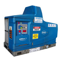
Nordson ProBlue P7 Customer Product Manual (320 pages)
Adhesive Melters
Brand:
Nordson
| Category:
Melting Machines
| Size: 3.98 MB
Table of Contents
Table of Contents
3
Safety Alert Symbols
11
Responsibilities of the Equipment Owner
12
Safety Information
12
Instructions, Requirements, and Standards
12
User Qualifications
13
Applicable Industry Safety Practices
13
Intended Use of the Equipment
13
Instructions and Safety Messages
14
Installation Practices
14
Operating Practices
14
Maintenance and Repair Practices
15
Equipment Safety Information
15
Equipment Shutdown
16
Relieving System Hydraulic Pressure
16
De‐Energizing the System
16
Disabling the Applicators
16
General Safety Warnings and Cautions
17
Other Safety Precautions
20
First Aid
20
Location of Safety Labels and Tags
21
‐2 General Safety Warnings and Cautions
21
Safety Labels and Tags
21
Description
23
Other Sources of Information
24
Installation Guide
24
User's Guide
24
Online Support
24
Product Resource CD
24
Product Description
25
System Components
25
Intended Use
26
Limitations of Use
26
Modes of Operation
26
Equipment Identification Plate
27
Melter Identification
27
Key Components
28
Control Panel
29
Optional Equipment
30
Installation
31
Quick‐Start
31
Installing 400/480 Volt Melters
31
Additional Information
32
Overview
32
Installation Tasks
33
Experience of Installation Personnel
33
Installation Requirements
34
Clearances
34
‐1 Installation Clearances
34
Ventilation
35
Electrical Power
35
Melter Cooling
35
Compressed Air
36
Other Considerations
36
Unpacking the Melter
38
Contents of the Installation Kit
38
Customer‐Supplied Materials
38
Installation Kit Components
39
Mounting the Melter
40
Mounting the Sub‐Base and the Melter
42
Configuring the Electrical Service
43
To Connect a Power Cable to the Melter
43
Melter Power Requirement
43
Connecting the Power Cable, Ground Lead, and Ground Jumper
45
Electrical Service Information
46
To Connect a Voltage Plug to the Melter
46
Connecting a Voltage Plug
47
Connecting a Compressed Air Supply
48
To Connect an Air Supply
48
Connecting the Air Filter and the Plant Air Supply Line
49
Connecting Hoses and Guns
50
To Connect Hoses
50
P10 6‐Hose Manifold Guard
51
Connecting a Hose
51
P10 Hose Routing Options
52
To Connect Guns
52
Setting up the Melter
54
Quick Setup
54
Common Operating Parameters
55
Operating Parameters
56
Selecting Operating Parameters
56
Reading or Editing Operating Parameters
56
To Read or Edit a Parameter
57
Set‐Point Temperature of the Tank, Hoses, and Guns
62
To Assign a Global Set‐Point Temperature
63
Save and Restore Melter Settings
64
To Save Current Settings
64
To Restore Saved Settings
64
Review Parameter and Set‐Point Temperature Changes
66
To Review the Change History Log
66
Change History Log
67
Change History Log Examples
67
Installing Melter Inputs
70
To Wire Inputs to the Melter
70
To Set up an Input
72
Input Data
73
Installing Melter Outputs
74
To Connect an Output to the Melter
74
Wiring Outputs
75
To Set up an Output
75
Installing Optional Equipment
77
Connecting a Gun Driver, Pattern Controller, or Timer
77
Flushing the Melter
77
Setting up Melter Communications
77
Operation
79
Additional Information
79
More about Heated Components
80
Filling the Tank
81
Tank Capacity
81
Starting the Melter
82
Melter Control Switch (On/Off)
82
Automatic Scan Sequence
82
Heaters LED
82
Monitoring the Melter
84
Confirm that the Melter Is Operating Correctly
85
Monitor Component Temperatures
86
To Check Component Temperatures Using the Automatic Scan Mode
86
To Manually Check a Component's Temperature
86
Monitor Melter Faults
88
To Review the Fault Log
88
Fault Log
89
Fault Log Examples
89
Melter Faults
90
To Put the Melter Back into Operation
91
How F1, F2, and F3 Faults Are Handled
92
How F4 Faults Are Handled
93
Monitor the Level of Hot Melt in the Tank
95
Monitor and Adjust the Operating Air Pressure
95
Monitor the Service Interval
96
To Reset the Service LED
96
Adjusting Component Temperatures
97
To Adjust Set‐Point Temperatures Using the Global Method
97
To Adjust the Set‐Point Temperature of an Individual Component
99
Entering the Melter Password
102
Using the Melter Function Keys
103
Heater Key
103
Special Function Keys
103
Standard Function Keys
103
Pump Key
104
Setup Key
104
Seven‐Day Clock Key
105
Standby Key
106
Shutting down the Melter
107
To Shut the Melter down
107
Maintenance
109
Preventive Maintenance Tasks
109
Relieving System Pressure
110
Locking out External Communications
110
Lowering the Drain Chute and Opening the Drain Valve
111
Cleaning the Melter
112
To Clean the Exterior of the Melter
112
To Remove and Replace the Exterior Panels
112
Removing the Exterior Panels
113
Replacing the Filter
114
Monitoring the Life of the Filter
114
To Replace the Filter
115
Cleaning the Tank
116
To Clean the Tank When Changing Hot Melt
116
To Clean the Tank of Excessive Char
117
Removing the Melter from the Sub‐Base
118
Troubleshooting
119
400/480 Volt Melters
119
Safety
119
Melter Faults
120
Using the Troubleshooting Flowchart
122
Before Using the Troubleshooting Charts Confirm
122
Troubleshooting Quick‐Checks
122
Identifying Electrical Components
123
Main PCA
123
Returning the Melter Setup to Factory Settings
123
6‐Hose Expansion Board (Optional)
124
CPU Board
124
Hose/Gun Power Module
124
Electrical Components
125
Power and Control Harness
126
Location of the Return Port
127
Pneumatic Flow Diagram
128
Diagnostic Procedures
129
DP.1 Isolate a Failed Control Component
129
DP.2 Check the Tank or Manifold RTD
130
Reheating the Melter During an F1 Fault
131
Remove the Tank RTD
131
Remove the Manifold RTD
132
DP.3 Check the Operation of the Power Relay or Thermostats
133
DP.4 Check the Operation of the Tank or Manifold TRIAC
134
DP.5 Check the Resistance of the Tank and Manifold Heaters
135
Heater Resistance
135
RTD Resistance Vs. Temperature
137
Removing the Pump
138
Problue Troubleshooting Flowcharts
139
Parts
165
Using the Illustrated Parts List
165
Tank, Pump, and Manifold Parts List
166
Manifold Assembly Parts List
168
Pump Assembly Parts Lists
171
15:1 Pump Assembly Parts
171
Pump Shifter Assembly Parts
182
Pump Piston Assembly Parts
184
Pneumatic Components Parts List
186
Electrical Enclosure Parts List
188
Exterior Panels Parts List
190
Chassis Components Parts List
192
Ribbon Cable Parts List
194
Service Kits
195
15:1 Pump Replacement
195
15:1 Low‐Viscosity Pump Replacement
195
6:1 Pump Replacement
195
Pump General Service
196
Filter
196
Pneumatic Panel
196
Pressure Discharge Valve
197
Manifold Service Kit
197
Main Circuit Board
198
Central Processor Unit (CPU)
198
Operator's Panel
198
Hose/Gun Module
198
Hose/Gun Module Fuses
199
Basic Spare Parts
199
Expanded Spare Parts
199
Level Switch
199
Option Kits
202
6‐Hose Extension
202
Input/Output Expansion Card
202
Devicenet Card
203
Profibus Card
203
P10 8 H/G Expansion Base
203
Schedule of Fasteners
204
Technical Data
205
General Specifications
205
Electrical Specifications
206
Pump Specifications
206
Melter Power Requirements
206
Dimensions
207
P4 Melter
207
P7 Melter
208
P7 Melter Dimensions
208
P10 Melter
209
P10 Melter Dimensions
209
Sub‐Base
210
Sub‐Base Dimensions
210
Wiring Diagrams—200/240 VAC Melter
211
Calculating Melter Power Requirements
221
To Evaluate the Hose/Gun Power Requirements
222
Hose/Gun Wattages
223
Maximum Allowable Wattages
223
Operating Parameters
225
Enter Password
226
Total Hours with Heaters on
226
Standard
226
Ready Delay Time
227
Service Interval Time
227
Service LED Heater Hours
228
Automatic Pump on
228
Automatic Pump on Temperature
228
Enable or Disable the Melter Password
229
Create Password
229
External Communications Lock-Out
229
Temperature Control
230
Temperature Units
230
Over Temperature Delta
230
Under Temperature Delta
230
Standby Delta
231
Automatic Standby Timeout
231
Automatic Heaters off Time
232
Manual Standby Time
232
Input Setup
233
Standard Input 1
233
Standard Input 2
233
Standard Outputs 1, 2, and 3
236
Optional Outputs 4, 5, 6, and 7
236
Output Setup
236
Seven‐Day Clock
238
To Set the Clock
238
Example 1
239
Example 2
239
Example 3
239
Current Day
240
Current Hour
240
Schedule 1 Heaters on
240
Schedule 1 Heaters off
240
Schedule 1 Enter Standby
241
Schedule 1 Exit Standby
241
Schedule 2 Heaters on
241
Schedule 2 Heaters off
242
Schedule 2 Enter Standby
242
Schedule 2 Exit Standby
242
Schedule 3 Heaters on
243
Schedule 3 Heaters off
243
Schedule 3 Enter Standby
243
Schedule 3 Exit Standby
244
Schedules for Monday
244
Schedules for Tuesday
245
Schedules for Wednesday
245
Schedules for Thursday
246
Schedules for Friday
246
Schedules for Saturday
247
Schedules for Sunday
247
Melter Communications
249
Software Availability
249
System Requirements
249
Installing the Software
250
Blue Series Software Versions
250
To Install Blue Series Software
251
Removing the Software from Your PC
252
To Remove Blue Series Software
252
Connecting the PC and the Melter
253
Using Nordson Configuration Manager
254
Saving and Restoring Melter Settings
254
To Save Melter Settings
254
To Restore Melter Settings
255
Upgrading or Restoring Melter Firmware
256
To Restore Pre‐Upgrade Melter Settings
258
Troubleshooting
259
Using Nordson Configuration Manager
259
SP Pump Diagnostics and Repair
261
Pump Function
261
Pump Isolation Valve
262
Pump Diagnostics
264
Pump Disassembly and Reassembly
266
Melter Preparation
266
Required Tools and Materials
266
Service Parts
267
Supplies
267
Lubricants and Compounds
267
Remove the Pump from the Melter
268
Special Reassembly Instructions
268
Remove the Actuator and Air Manifold and the Cylinder Assembly
270
Remove the Magnetic Actuator Assembly
272
Remove the Valve Spool and Sleeve
275
Remove the Shifter Fork
278
Remove the Piston Cups
280
Remove the Pump Frame and the Insulator
282
Remove the Lower Ball Seat Assembly and the Piston
286
Disassemble the Lower Ball Seat and the Pressure Ball Assemblies
288
Remove the O‐Ring and the Pump Seal
290
400/480 Volt Problue Adhesive Melters
295
Unintended Use
296
Transformer Sizing
297
Hose and Gun Power Consumption
298
Transformer Function
299
Prepare the Transformer for Installation
302
Preparing the Transformer
302
Installing the Voltage Plug
303
Mount the Transformer to the Parent Machine
304
Mounting the Sub‐Base and the Transformer
305
Connect the Electrical Service to the Transformer
306
Maximum Melter Amperages
306
Connecting the Electrical Service
307
Mount the Melter to the Transformer
308
Connecting the Melter Ground Lead to the Transformer Chassis
309
Connect the Transformer to the Melter
310
Connecting the Transformer Electrical Harnesses
311
Covering the Service Entrance
312
Transformer Assembly
314
400/480‐Volt Melter‐Specific Components
317
Wiring Diagram
317
Advertisement
Advertisement
Related Products
Nordson ProBlue P4
Nordson ProBlue P10
Nordson ProBlue Flex
Nordson ProBlue 1028303
Nordson PRODIGY
Nordson PowderPilot HD
Nordson PURBlue 4
Nordson PatternCoat Series
Nordson PCT140 W-B Series
Nordson Prodigy HDLV Pump Generation II
Nordson Categories
Paint Sprayer
Industrial Equipment
Controller
Dispenser
Control Unit
More Nordson Manuals
Login
Sign In
OR
Sign in with Facebook
Sign in with Google
Upload manual
Upload from disk
Upload from URL