Sign In
Upload
Manuals
Brands
Nidek Medical Manuals
Edger
SE-9090 Supra
Nidek Medical SE-9090 Supra Manuals
Manuals and User Guides for Nidek Medical SE-9090 Supra. We have
1
Nidek Medical SE-9090 Supra manual available for free PDF download: Service Manual
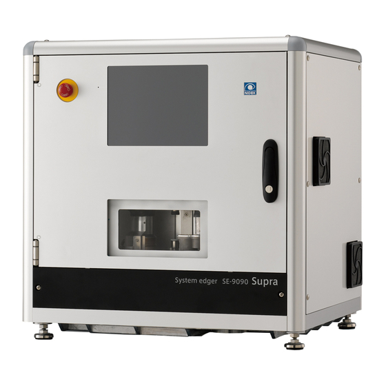
Nidek Medical SE-9090 Supra Service Manual (350 pages)
SYSTEM EDGER
Brand:
Nidek Medical
| Category:
Edger
| Size: 61.52 MB
Table of Contents
Table of Contents
3
Introduction
13
Safety Precautions
15
Specifications
17
Safety Features
17
Processing Specifications
18
Interface Specifications
21
Power Requirements
21
Dimensions and Mass
21
Environmental Conditions
21
Troubleshooting
23
Subtroubleshooting
25
Nothing Is Displayed on Screen
25
Backlight of Color LCD Does Not Illuminate
26
Power Supply Check
27
Error Message Appears
28
Error 1 (Communication Timeout Error)
28
Error 2 (Lens Material Mismatch Error)
28
Error 2 (Communication Error)
28
Error 102 (Front Cover Error)
29
Error 103 (H-Axis Inside Limit Error)
30
Error 104 (V-Axis Upper Limit Error)
31
Error 105 (Roughing End Error)
32
Error 106 (Finishing End Error)
33
Error 107 (Polishing End Error)
34
Error 108 (Grooving End Error)
35
Error 109 (Step Beveling End Error)
36
Error 110 (H- Axis Outside Limit Error)
37
Error 111 (V-Axis Lower Limit Error)
37
Error 112 (Initialization Error)
37
Error 201 (LMU Feeler off Error)
38
Error 202 (LMU Lens Detection Error)
39
Error 203 (LMU Lens Thickness Error)
40
Error 204 (LMU Start and End Points Error)
41
Error 205 (LMU Origin Sensor Error)
42
Lens Measuring ASSY Does Not Move Forward or Backward
43
Error 206 (LMU Rear Feeler Origin Sensor Error)
44
Feelers Do Not Open or Close
45
Encoder Value for Rear Feeler Does Not Change
46
Error 207 (LMU Front Feeler Origin Sensor Error)
47
Encoder Value for Front Feeler Does Not Change
48
Error 208 (LMU Operation End Error)
49
Error 209 (LMU Feeler Close Error)
51
Error 210 (LMU Feeler Origin Sensor off Error)
52
Error 214 (LMU Rear Feeler Encoder Error)
52
Error 215 (LMU Front Feeler Encoder Error)
53
Error 301 (Calculation Error)
53
Error 302 (EEPROM Checksum Error)
53
Error 304 (EEPROM Data Error)
53
Error 401 (Right Wheel Motor or Inverter Error)
54
Error 402 (Left Wheel Motor or Inverter Error)
55
Error 501 (Right H-Axis Origin Sensor Error)
56
Right Processing ASSY Does Not Move Right or Left
57
Error 502 (Right V-Axis Origin Sensor Error)
58
Right Processing ASSY Does Not Move up or down
59
Error 503 (Left H-Axis Origin Sensor Error)
60
L Spindle Block ASSY Does Not Move Right or Left
61
Error 504 (Left V-Axis Origin Sensor Error)
62
L Spindle Block ASSY Does Not Move up or down
63
Error 505 (Lower Rotation Axis Origin Sensor Error)
64
Lower Shaft ASSY Does Not Rotate
65
Error 506 (Upper Rotation Axis Origin Sensor Error)
66
Upper Shaft ASSY Does Not Rotate
67
Error 507 (Right H-Axis Limit Error)
68
Error 508 (Right V-Axis Limit Error)
68
Error 509 (Left H-Axis Limit Error)
69
Error 510 (Left V-Axis Limit Error)
69
Error 511 (Right H-Axis Move End Error)
69
Error 512 (Right V-Axis Move End Error)
69
Error 513 (Left H-Axis Move End Error)
69
Error 514 (Left V-Axis Move End Error)
69
Error 515 (Lower Rotation Axis Move End Error)
69
Error 516 (Upper Rotation Axis Move End Error)
69
Error 601 (Chuck Open Error)
70
Upper Shaft ASSY Does Not Move up or down
71
Error 602 (Chuck Close Error)
72
Error 701 (Cover Open Error)
73
Motorized Cover ASSY Does Not Operate
74
Error 702 (Cover Close Error)
74
Error 801 (SD Card Detection Error)
75
Error 808 (USB Flash Drive Detection Error)
76
Error 9** (RHU Error)
76
Error 1*** (VCA Communication Error)
76
Error 1989 (VCA Format Error)
76
Error 1990 (VCA Receiving Data Overflow Error)
77
Error 1991 (VCA Lens Material Mismatch Error)
77
Error 2001 (Grooving Unit Initialization Error)
77
Grooving ASSY Does Not Move Forward or Backward
78
Error 2002 (Grooving Overcurrent Error)
78
Error 2003 (Step Beveling Overcurrent Error)
79
Error 2004 (Grooving Motor Error)
80
Error 2101 (RH Motor Communication Error)
80
Error 2102 (RV Motor Communication Error)
81
Error 2103 (LH Motor Communication Error)
81
Error 2104 (LV Motor Communication Error)
82
Error 2105 (UR Motor Communication Error)
82
Error 2106 (LR Motor Communication Error)
83
Error 2107 (Chuck Motor Communication Error)
83
Error 2108 (LMU Motor Communication Error)
84
Error 2201 (Calibration Sensor Error)
85
Error 10001 (too Small Lens Shape)
86
Error 2301 (I/O Board Error)
86
Error 10002 (Emergency Button Is Pressed.)
87
Error 10003 (too Thin Lens)
87
Error 10007 (no Right-Lens Data)
87
Error 10008 (no Left-Lens Data)
87
Error 10010 (too Thick Lens)
87
Error 10012 (too Large Lens Shape)
87
Error 10014 (Bevel Position Comes Off.)
87
Initialization of Instrument Does Not Complete
88
Touch Panel Is Not Operational
89
External Data Cannot be Received Properly
90
Lens Processing Is Not Performed Properly
91
Cooling Water Does Not Come out
91
Processing Time Is Overly Long
93
Roughing Time Is Overly Long
93
Finishing Time Is Overly Long or Does Not Complete
94
Safety Beveling Time Is Overly Long or Does Not Complete
95
Lens Finish Size Is Not Proper
96
Wheel Stops During Processing
96
Axi Shift Occur
97
Axis Shift Occurs
97
Lens Is Not Beveled Properly
98
Lens Is Not Safety Beveled Properly
99
Lens Is Not Polished Properly
100
Flat Edge Is Not Polished Properly
100
Beveled Edge Is Not Polished Properly
101
Safety Beveled Edge Is Not Polished Properly
102
There Are Burns on Polished Surface of Safety Beveled Edge
103
Removal Procedure
105
Opening Front Cover ASSY
105
Left Panel (40274-M142)
106
Right Panel (40274-M143)
106
Exterior Panel ASSY (40274-1200)
107
Front Panel (40274-M146)
107
Top Panel (40274-M144)
108
Attaching the Splatter Guard (40274-M051)
108
Replacement Procedure
109
Assys
109
Display ASSY (40274-1110)
109
Motorized Cover ASSY (40274-1120)
110
Motorized Cover Motor ASSY (40274-1121)
110
F/L Support ASSY (40274-1310)
111
F/R Support ASSY (40274-1320)
112
R/L Support ASSY (40274-1330)
113
R/R Support ASSY (40274-1340)
114
R V-Axis ASSY (40274-2300)
115
L V-Axis ASSY (40274-2400)
116
R H-Axis ASSY (40274-2500)
117
L H-Axis ASSY (40274-2600)
118
Lower Rotation Axis ASSY (40274-3000)
119
Processing Chamber ASSY (40274-4000)
120
Upper Shaft ASSY (40274-5000)
121
Chuck Base ASSY (40274-5100)
122
Rotation ASSY (40274-5200)
123
Lens Measuring ASSY (40274-6000)
123
Slider ASSY (40274-6100)
124
Measuring Window ASSY (40274-6200)
125
Right Processing Base ASSY (40274-7100)
126
Right Processing ASSY (40274-7200, 40274-72S0)
130
Grooving ASSY (40274-7210, 40274-721S)
131
L Spindle Block ASSY (40273-7200)
133
L Wheel Cover ASSY (40274-7400)
135
Driver ASSY (40274-8000)
136
Lens Clamp ASSY (40251-3200)
136
Wheels (40291-0100, 40291-0500, 40291-0700)
137
Cable Assys
139
Cable ASSY (40274-CA12)
139
Sensor ASSY (40274-CA26)
140
Cable ASSY (40274-CA31)
141
Cable ASSY (40274-CA32)
141
Sensor ASSY (40274-CA33)
142
Sensor ASSY (40273-CA34)
142
Sensor ASSY (40273-CA35)
143
Sensor ASSY (40274-CA34)
143
Sensor ASSY (40274-CA35)
144
Sensor ASSY (40274-CA36)
144
Sensor ASSY (40274-CA37)
145
Sensor ASSY (40274-CA38)
145
Sensor ASSY (40274-CA39)
146
Boards
147
Main Board (44501-BA01)
147
Connection Board (40274-BA02)
147
LMU Board (40271-BA03)
148
I/O Board (40274-BA06)
149
SSR Board (44501-BA09)
149
Interface Board (40274-BA11)
150
Inverter (42203-E017)
150
USB Board (44501-BA13)
151
Electrical Parts
152
Brushless Motor (40273-E010)
152
Brushless Motor (40273-E010) for Right Processing Base ASSY
152
Brushless Motor (40273-E010) for Left Spindle Block ASSY
153
Closed Loop Stepping Motor (40274-E016)
154
Closed Loop Stepping Motor (40274-E017)
155
Closed Loop Stepping Motor (40274-E018)
156
Closed Loop Stepping Motor (40274-E018) for R. H. PM
156
Closed Loop Stepping Motor (40274-E018) for R. V. PM
157
Closed Loop Stepping Motor (40274-E018) for L. H. PM
158
Closed Loop Stepping Motor (40274-E018) for L. V. PM
159
Closed Loop Stepping Motor (40274-E018) for CHUCK PM
160
Closed Loop Stepping Motor (40274-E018) for LMU PM
162
Closed Loop Motor Driver (40274-E019)
163
Color LCD Module (40273-E020)
163
DC Motor (40274-E027)
164
Rotary Encoder (40273-E027)
165
Rotary Encoder (40273-E028)
165
Stepping Motor (40273-E029) for LMU. F. PM
166
DC Fan (40271-E031)
167
BL Motor Inverter (40350-E052)
168
Stepping Motor (80407-00216) for COVER MOTOR
169
Stepping Motor (80407-00217) for G_R PM
170
Breaker (80431-00025)
171
Line Noise Filter (80404-00036)
171
Switching Regulator (80602-00101)
172
Mechanical Parts
173
Lens Adapter (40251-M045)
173
Feeler (40274-M673)
173
Spindle (40273-M711)
174
Spindle (40273-M711) of Left Spindle Block ASSY
174
Spindle (40273-M711) of Right Processing ASSY
176
Timing Belt (40274-M736) of Grooving ASSY
177
Grooving Wheel (43131-M001)
178
Step Beveling Wheel (40274-M745)
178
Adjustment
179
Displaying each Screen
179
Menu Screen
179
Hardware Test Screen
180
Hardware Test Screen Indications
181
Hardware Test Screen Explanations
182
Password Settings
185
Password for In-House Maintenance Personnel
185
Password for Distributor
186
Touch Panel Calibration
187
Chuck Pressure Measurement
188
Measuring Window ASSY Position Adjustment
189
Upper/Lower Shaft Position Adjustment
190
Motorized Cover Sensor Position Adjustment
191
Grooving ASSY Adjustment
193
Position Adjustment
193
Rotation Axis Adjustment
195
Belt Tension Adjustment
196
Left Spindle Block ASSY Belt
196
Right Processing Base ASSY Belt
197
Axis Smoothness Check
198
H Axis
198
Q Axis
199
Loading Internal Data
200
Calibration
201
Touch Sensor Type Calibration Jig (40300-0970)
201
LMU Calibration
202
Wheel Calibration
203
Groove Calibration
204
LMU Measurement Position Adjustment
205
Lens Measurement Position
205
Lens Measurement Position Check
205
Lens Measurement Position Adjustment
206
Lens Measurement Axis
207
Lens Measurement Axis Check
207
Lens Measurement Axis Adjustment
208
Processing Adjustment
209
Axis Adjustment
210
Bevel Axis Check
210
Using the Axis Angle Adjustment Jig
210
Bevel Axis Adjustment
211
Flat Axi Check
213
Flat Axis Check
213
Flat Axis Adjustment
214
Bevel Axis Check
216
Using Graph Paper
216
Bevel Axis Adjustment
217
Flat Axi Check
219
Flat Axis Check
219
Flat Axis Adjustment
220
Finish Size Adjustment
222
Bevel Finish Size Check
222
Bevel Finish Size Adjustment
223
Retouch Check
224
Flat Finish Size Check
225
Flat Finish Size Adjustment
226
Bevel Position
227
Bevel Position Check
227
Bevel Position Adjustment
228
Flat Polish Adjustment
229
Flat-Edge Polishing Wheel Position Check
229
Flat-Edge Polishing Wheel Position Adjustment
230
Flat Polish Axis Check
232
Flat Polish Axis Adjustment
233
Adjusting Flat Edge Polishing Marks
236
Flat Polish Size Check
238
Flat Polish Size Adjustment
239
Bevel Polish Adjustment
240
Checking the Position of Polishing Wheel for Beveled Surface
240
Adjusting the Position of Polishing Wheel for Beveled Edge
241
Vertical Position
241
Horizontal Position
243
Adjusting Beveled Edge Polishing Marks
245
Bevel Polish Size Check
248
Bevel Polish Size Adjustment
249
Safety Bevel Size Adjustment
250
SFB Finish Size Check
250
SFB Finish Size Adjustment
251
SFB Polish Size Check
252
SFB Polish Size Adjustment
254
SFB Axis Adjustment
255
SFB Finish Axis Check
255
SFB Finish Axis Adjustment
256
SFB Polish Axis Check
259
SFB Polish Axis Adjustment
260
Special SFB Adjustment
262
Special SFB Polish Check
262
Special SFB Polish Adjustment
263
Checking for Interference between Bevel and Polishing Wheel for Safety-Beveled Front Surface
264
Grooving Adjustment
265
Grooving Width Check
265
Groove Position Check
266
Groove Position Adjustment
267
Groove Depth Check
268
Groove Depth Adjustment
269
Groove Axis Check
270
Groove Axis Adjustment
271
High Base Curve Bevel Adjustment
273
High Base Curve Bevel Finish Size Check
273
High Base Curve Bevel Finish Size Adjustment
274
High Base Curve Bevel Polish Check
275
Adjusting the Position of Polishing Wheel for High Base Curve
276
Beveled Edges
276
Horizontal Adjustment of Polishing Wheel for High Base Curve Beveled Edges
276
Vertical Adjustment of Polishing Wheel for High Base Curve Beveled Edges
278
High Base Curve Bevel Polish Size Check
279
High Base Curve Bevel Polish Size Adjustment
280
Step Bevel Adjustment
282
Step Bevel Check
282
Step Bevel Position Adjustment
283
Step Bevel Height Adjustment
284
Step Bevel Axis Check
285
Step Bevel Axis Adjustment
286
Network Setting
288
Dressing the Wheels
289
Finishing Wheel
289
Step Beveling Wheel
290
Grooving Wheel
291
Finishing Wheel for Safety-Beveled Edges
292
Maintaining the Polishing Wheel with Compound
292
Polishing Wheel
292
Polishing Wheel for Safety-Beveled Edges
293
Adjusting the Feeler Movement
294
EEPROM Data
296
Backing up the EEPROM Data
296
Restoring the EEPROM Data
297
Upgrade
298
Program Upgrade
298
String Resource Upgrade
299
Booter Program Upgrade
300
Version Check
301
Setting BL Motor Inverter
302
Parameter Settings
302
Trip Check
303
Supplement
305
Appearance
305
Labels and Indications
308
Wiring Diagram
310
Connector Cable
311
Layout Drawing
313
Assys
313
Boards
318
Cable Assys
320
Other Electrical Components
321
Wheel Configurations
323
Error Code List
324
Parameter List
329
Jigs and Tools
336
Jig and Tool
336
Jigs
336
Tools (Standard Accessories)
337
Adjustment List
338
Adjustments after Replacing Assys
338
Adjustments after Replacing Cables
341
Adjustments after Replacing Boards
342
Adjustments after Replacing Electrical Parts
343
Adjustments after Replacing Mechanical Parts
347
Screw List
349
Advertisement
Advertisement
Related Products
Nidek Medical SE-9090 Express
Nidek Medical Express LE-9000 Series
Nidek Medical Le 1000
Nidek Medical LE-700
Nidek Medical LE-9000DX Express
Nidek Medical LE-9000EX Express
Nidek Medical LE-9000LX
Nidek Medical LE-9000SX
Nidek Medical Lex 1000
Nidek Medical ME 1200
Nidek Medical Categories
Medical Equipment
Measuring Instruments
Edger
Oxygen Equipment
Projector
More Nidek Medical Manuals
Login
Sign In
OR
Sign in with Facebook
Sign in with Google
Upload manual
Upload from disk
Upload from URL