Sign In
Upload
Manuals
Brands
Komatsu Manuals
Other
PC130-8
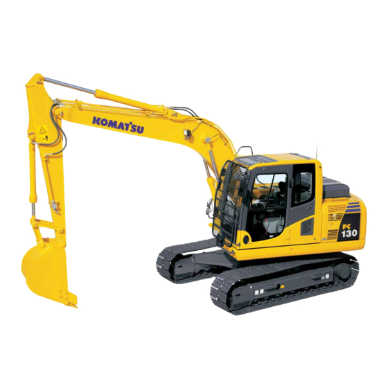
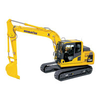
Komatsu PC130-8 Hydraulic Excavator Manuals
Manuals and User Guides for Komatsu PC130-8 Hydraulic Excavator. We have
3
Komatsu PC130-8 Hydraulic Excavator manuals available for free PDF download: Shop Manual, Brochure
KOMATSU PC130-8 Shop Manual (1043 pages)
HYDRAULIC EXCAVATOR
Brand:
KOMATSU
| Category:
Excavators
| Size: 69.54 MB
Table of Contents
Table of Contents
6
Safety Notice
16
How to Read the Shop Manual
21
Explanation of Terms for Maintenance Standard
23
Handling of Electric Equipment and Hydraulic Component
25
Handling of Connectors Newly Used for Engines
34
How to Read Electric Wire Code
37
Precautions When Carrying out Operation
40
Method of Disassembling and Connecting Push-Pull Type Coupler
43
Standard Tightening Torque Table
46
Conversion Table
50
Specification
57
Specification Dimension Drawings
58
Working Range Diagram
59
Specifications
60
List of Weights
64
List of Lubricant and Coolant to be Filled
66
Structure, Function and Maintenance Standard
69
Engine and Cooling System SEN03770-01
69
Engine Mount
70
Pto
71
Cooling System
72
Power Train SEN03771-01
75
Power Train
75
Swing Circle
77
Swing Machinery
78
Track Frame
82
Idler Cushion
83
Idler
84
Track Roller
85
Carrier Roller
86
Sprocket
87
Track Shoe
88
Hydraulic System, Part 1
93
Hydraulic Equipment Layout Drawing
94
Valve Control
96
Hydraulic Tank and Filter
98
Hydraulic Pump
100
Hydraulic System, Part 2
129
Control Valve
130
Clss
140
Functions and Operation by Valve
144
Hydraulic System, Part 3
175
PPC Valve
176
Swing Motor
191
Travel Motor
199
Center Swivel Joint
208
Solenoid Valve
210
Accumulator
214
Anti-Drop Valve for Boom
216
Anti-Drop Valve for Arm
221
Hydraulic Cylinder
226
Work Equipment SEN03776-00
229
Work Equipment
229
Dimensions of Components
232
Cab and Its Attachments SEN03777-00
237
Air Conditioner
238
Electronic Control System
242
Machine Monitor System
274
KOMTRAX System
288
Sensor
290
Standard Value Table
299
Standard Value Table for Engine Related Parts
300
Standard Value Table for Chassis Related Parts
301
Testing and Adjusting Testing and Adjusting, Part
311
Tools for Testing, Adjusting, and Troubleshooting
313
Sketches of Special Tools
318
Testing Engine Speed
319
Testing Exhaust Temperature
320
Checking Exhaust Gas Color
321
Adjusting Valve Clearance
322
Testing Compression Pressure
324
Testing Blow-By Pressure
326
Testing Engine Oil Pressure
327
Reduced Cylinder Mode Operation
328
No-Injection Cranking
328
Handling Fuel System Parts
329
Releasing Residual Pressure from Fuel System
329
Testing Fuel Pressure
330
Testing Fuel Return Rate and Fuel Leakage
331
Bleeding Air from Fuel Circuit
333
Checking Fuel Circuit for Leakage
334
Testing and Adjusting Alternator Belt Tension
335
Checking and Adjusting Air Conditioner Compressor Belt Tension
336
Testing Swing Circle Bearing Clearance
337
Checking and Adjusting Track Shoe Tension
338
Testing and Adjusting Oil Pressure in Work Equipment, Swing, and Travel Circuits
340
Testing Control Circuit Basic Pressure
343
Testing and Adjusting Oil Pressure in Pump PC Control Circuit
344
Testing and Adjusting Oil Pressure in Pump LS Control Circuit
347
Testing Solenoid Valve Output Pressure
350
Testing PPC Valve Output Pressure
354
Adjusting Play of Work Equipment and Swing PPC Valves
355
Checking Parts Which Cause Hydraulic Drift of Work Equipment
356
Testing and Adjusting Travel Deviation
358
Releasing Residual Pressure from Hydraulic Circuit
360
Testing Oil Leakage
363
Bleeding Air from each Part
366
Checking Cab Tipping Stopper
368
Installation and Adjustment of Mirrors and Camera
369
Inspection of Air Conditioner Recirc/Fresh Air Filter
380
Testing and Adjusting, Part 2
383
Special Functions of Machine Monitor
384
Testing and Adjusting, Part 3
435
Handling Voltage Circuit of Engine Controller
436
Testing and Adjusting
436
Preparation Work for Troubleshooting of Electrical System
437
Procedure for Testing Diodes
442
Pm Clinic Service
443
Troubleshooting
449
Failure Code Table
450
Fuse Locations
454
Points to Remember When Troubleshooting
458
Troubleshooting
458
Sequence of Events in Troubleshooting
459
Checks before Troubleshooting
460
Classification and Procedures for Troubleshooting
461
Information in Troubleshooting Table
462
Phenomena Looking Like Troubles and Troubleshooting Nos
464
Connection Table for Connector Pin Numbers
467
T- Branch Box and T- Branch Adapter Table
503
Troubleshooting by Failure Code, Part 1
507
Failure Code [989L00] Engine Controller Lock Caution 1
509
Failure Code [989M00] Engine Controller Lock Caution 2
509
Failure Code [989N00] Engine Controller Lock Caution 3
510
Failure Code [AA10NX] Air Cleaner Clogging
511
Troubleshooting
511
Failure Code [AB00KE] Charge Voltage Low
512
Failure Code [B@BAZG] Eng Oil Press. Low
514
Failure Code [B@BAZK] Eng Oil Level Low
515
Failure Code [B@BCNS] Eng Coolant Overheat
516
Failure Code [B@BCZK] Eng Water Level Low
518
Failure Code [B@HANS] Hydr Oil Overheat
520
Failure Code [CA111] ECM Critical Internal Failure
522
Failure Code [CA115] Eng Ne and Bkup Speed Sensor Error
525
Failure Code [CA122] Charge Air Press Sensor High Error
526
Failure Code [CA123] Charge Air Press Sensor Low Error
528
Failure Code [CA131] Throttle Sensor High Error
530
Failure Code [CA132] Throttle Sensor Low Error
532
Failure Code [CA144] Coolant Temp. Sensor High Error
534
Failure Code [CA145] Coolant Temp. Sensor Low Error
536
Failure Code [CA153] Charge Air Temp. Sensor High Error
538
Failure Code [CA154] Charge Air Temp. Sensor Low Error
540
Failure Code [CA155] Chg Air Temp High Speed Derate
540
Failure Code [CA187] Sensor Sup. 2 Volt. Low Error
541
Failure Code [CA221] Ambient Air Press. Sensor High Error
542
Failure Code [CA222] Ambient Air Press. Sensor Low Error
544
Failure Code [CA227] Sensor Sup. 2 Volt. High Error
545
Failure Code [CA234] Eng. Overspeed
546
Failure Code [CA238] Ne Speed Sensor Sup. Volt. Error
548
Failure Code [CA271] IMV/PCV1 Short Error
550
Failure Code [CA272] IMV/PCV1 Open Error
551
Failure Code [CA322] Injector #1 (L #1) System Open/Short Error
552
Failure Code [CA324] Injector #3 (L #3) System Open/Short Error
554
Failure Code [CA331] Injector #2 (L #2) System Open/Short Error
556
Failure Code [CA332] Injector #4 (L #4) System Open/Short Error
558
Troubleshooting by Failure Code, Part 2
561
Failure Code [CA342] Calibration Code Incompatibility
563
Troubleshooting
563
Failure Code [CA351] Inj. Drive Circuit Error
564
Failure Code [CA352] Sensor Sup. 1 Volt. Low Error
567
Failure Code [CA386] Sensor Sup. 1 Volt. High Error
568
Failure Code [CA435] Abnormality in Engine Oil Pressure Switch
570
Failure Code [CA441] Battery Voltage Low Error
571
Failure Code [CA442] Battery Voltage High Error
572
Failure Code [CA449] Rail Press. very High Error
573
Failure Code [CA451] Rail Press. Sensor High Error
574
Failure Code [CA452] Rail Press. Sensor Low Error
576
Failure Code [CA488] Chg Air Temp High Torque Derate
577
Failure Code [CA553] Rail Press. High Error
578
Failure Code [CA559] Rail Press. Low Error
579
Failure Code [CA689] Eng. Ne Speed Sensor Error
582
Failure Code [CA731] Eng. Bkup Speed Sensor Phase Error
584
Failure Code [CA757] All Persistent Data Lost Error
585
Failure Code [CA778] Eng. Bkup Speed Sensor Error
586
Failure Code [CA1633] KOMNET Datalink Timeout Error
588
Failure Code [CA2185] Throttle Sens. Sup. Volt. High Error
590
Failure Code [CA2186] Throttle Sens. Sup. Volt. Low Error
592
Failure Code [CA2249] Rail Press. very Low Error
592
Failure Code [CA2311] Abnormality in IMV Solenoid
593
Failure Code [D110KB] Battery Relay Drive Short
594
Failure Code [D19JKZ] Personal Code Relay Abnormality
596
Failure Code [D862KA] GPS Antenna Discon
598
Failure Code [DA22KK] Pump Solenoid Power Low Error
600
Failure Code [DA25KP] 5V Sensor 1 Power Abnormality
602
Failure Code [DA26KP] 5V Sensor 2 Power Abnormality
605
Failure Code [DA29KQ] Model Selection Abnormality
606
Troubleshooting by Failure Code, Part 3
609
Failure Code [DA2RMC] CAN Discon (Pump Controller Detected)
612
Troubleshooting
612
Failure Code [DAF8KB] Short Circuit in Camera Power Supply
614
Failure Code [DAFGMC] GPS Module Error
616
Failure Code [DAFRMC] CAN Discon (Monitor Detected)
618
Failure Code [DGH2KB] Hydr Oil Sensor Short
620
Failure Code [DHPAMA] Pump Press Sensor Abnormality
622
Failure Code [DHSFMA] Travel Left Forward PPC Press Sensor Abnormality
624
Failure Code [DHSGMA] Travel Right Forward PPC Press Sensor Abnormality
626
Failure Code [DHSHMA] Travel Left Reverse PPC Press Sensor Abnormality
628
Failure Code [DHSJMA] Travel Right Reverse PPC Press Sensor Abnormality
630
Failure Code [DHX1MA] Overload Sensor Abnormality (Analog)
632
Failure Code [DV20KB] Travel Alarm Short Circuit
633
Failure Code [DW43KA] Travel Speed Sol Discon
634
Failure Code [DW43KB] Travel Speed Sol Short
635
Failure Code [DW45KA] Swing Brake Sol Discon
636
Failure Code [DW45KB] Swing Brake Sol Short
638
Failure Code [DW91KA] Travel Junction Sol Discon
640
Failure Code [DW91KB] Travel Junction Sol Short
642
Failure Code [DWJ0KA] Merge-Divider Sol Discon
644
Failure Code [DWJ0KB] Merge-Divider Sol Short
646
Failure Code [DWK0KA] 2-Stage Relief Sol Discon
648
Failure Code [DWK0KB] 2-Stage Relief Sol Short
650
Troubleshooting by Failure Code, Part 4
653
Failure Code [DXA8KA] PC-EPC Sol Discon
654
Troubleshooting
654
Failure Code [DXA8KB] PC-EPC Sol Short
656
Failure Code [DXE4KA] Service Current EPC Discon
658
Failure Code [DXE4KB] Service Current EPC Short
660
Failure Code [DY20KA] Wiper Working Abnormality
662
Failure Code [DY20MA] Wiper Parking Abnormality
664
Failure Code [DY2CKA] Washer Drive Discon
666
Failure Code [DY2CKB] Washer Drive Short
668
Failure Code [DY2DKB] Wiper Drive (For) Short
670
Failure Code [DY2EKB] Wiper Drive (Rev) Short
672
Before Carrying out Troubleshooting of Electrical System
677
Troubleshooting
677
Information in Troubleshooting Table
679
When Starting Switch Turned ON, Machine Monitor Displays Nothing
680
When Starting Switch Turned on (before Starting Engine), Basic Check Item Lights up
682
Engine Does Not Start (Engine Does Not Turn)
685
Preheater Does Not Operate
688
Automatic Warm-Up System Does Not Operate (in Cold Season)
690
All Work Equipment, Swing, and Travel Mechanism Do Not Move or Cannot be Locked
692
Precaution Lights up While Engine Is Running
694
Emergency Stop Item Lights up While Engine Is Running
699
Engine Coolant Temperature Gauge Does Not Indicate Normally
700
Hydraulic Oil Temperature Gauge Does Not Indicate Normally
701
Fuel Level Gauge Does Not Indicate Normally
703
Contents of Display by Machine Monitor Are Different from Applicable Machine
705
Function Switch Does Not Work
705
Machine Monitor Does Not Display some Items
705
Auto-Decelerator Does Not Operate Normally
706
Working Mode Does Not Change
707
Travel Speed Does Not Change
708
Alarm Buzzer Cannot be Stopped
709
Windshield Wiper and Window Washer Do Not Operate
710
Power Maximizing Function Does Not Operate Normally
714
Swing Holding Brake Does Not Operate Normally
716
Travel Alarm Does Not Sound or Does Not Stop Sounding
718
Air Conditioner Does Not Operate Normally (Including Air Conditioner Abnormality Record)
719
Machine Monitor Cannot be Set in Service Mode
731
While Starting Switch Is in off Position, Service Meter Is Not Displayed
731
Monitoring Function Does Not Display Lever Control Signal Normally
732
KOMTRAX System Does Not Operate Normally
748
Information Contained in Troubleshooting Table
753
System Chart for Hydraulic and Mechanical Systems
754
Speed or Power of All Work Equipment, Swing, and Travel Are Low
756
Engine Speed Sharply Drops or Engine Stalls
757
Abnormal Noise Is Heard from Around Hydraulic Pump
758
No Work Equipment, Travel and Swing Move
758
Fine Control Mode Does Not Function
759
Speed or Power of Boom Is Low
760
Speed or Power of Arm Is Low
761
Speed or Power of Bucket Is Low
762
Work Equipment Does Not Move in Its Single Operation
763
Hydraulic Drift of Work Equipment Is Large
764
Power Maximizing Function Does Not Operate Normally
765
Time Lag of Work Equipment Is Large
765
Work Equipment Loaded more Is Slower During Compound Operation
766
Boom RAISE Speed Is Low in Compound Operation of Swing + Boom RAISE
766
Travel Speed Lowers Largely During Compound Operation of Work Equipment/Swing + Travel
767
Machine Deviates During Travel
768
Travel Speed Is Low
769
Machine Cannot be Steered Easily or Steering Power Is Low
770
Travel Speed Does Not Change or It Is Kept Low or High
771
Track Does Not Move (Only Either Side)
771
Machine Does Not Swing
772
Swing Acceleration or Swing Speed Is Low
773
Excessive Overrun When Stopping Swing
774
When Upper Structure Stops Swinging, It Makes Large Shock
775
When Upper Structure Stops Swinging, It Makes Large Sound
775
Hydraulic Drift of Swing Is Large
776
Flow Rate in Attachment Circuit Cannot be Adjusted
777
Method of Using Troubleshooting Chart
782
Starting Performance Is Poor
786
Engine Does Not Start
787
Engine Does Not Pick up Smoothly
790
Engine Stops During Operations
791
Engine Does Not Rotate Smoothly
792
Engine Lacks Output (or Lacks Power)
793
Exhaust Smoke Is Black (Incomplete Combustion)
794
Oil Consumption Is Excessive (or Exhaust Smoke Is Blue)
795
Oil Becomes Contaminated Quickly
796
Fuel Consumption Is Excessive
797
Oil Is in Coolant (or Coolant Spurts Back or Coolant Level Goes Down)
798
Oil Pressure Drops
799
Oil Level Rises (Entry of Coolant or Fuel)
800
Coolant Temperature Becomes too High (Overheating)
801
Abnormal Noise Is Made
802
Vibration Is Excessive
803
Disassembly and Assembly
806
How to Read this Manual
806
Coating Materials List
808
Special Tool List
811
Sketch of Special Tool
815
Removal and Installation of Fuel Supply Pump Assembly
822
Removal and Installation of Fuel Injector Assembly
825
Removal and Installation of Front Oil Seal
828
Removal and Installation of Rear Oil Seal
830
Removal and Installation of Cylinder Head Assembly
833
Removal and Installation of Radiator Assembly
843
Removal and Installation of Aftercooler Assembly
845
Removal and Installation of Work Equipment Oil Cooler Assembly
847
Removal and Installation of Engine and Work Equipment Pump Assembly
849
Removal and Installation of Fuel Tank Assembly
857
Removal and Installation of Travel Motor and Final Drive Assembly
862
Disassembly and Assembly of Travel Motor and Final Drive Assembly
864
Removal and Installation of Swing Motor and Swing Machinery Assembly
901
Disassembly and Assembly of Swing Machinery Assembly
903
Removal and Installation of Swing Circle Assembly
909
Disassembly and Assembly of Track Roller
912
Disassembly and Assembly of Idler Assembly
915
Disassembly and Assembly of Recoil Spring
918
Spreading and Installation of Track Shoe Assembly
921
Removal and Installation of Sprocket
923
Removal and Installation of Revolving Frame Assembly
924
Removal and Installation of Counterweight Assembly
926
Removal and Installation of Center Swivel Joint Assembly
930
Disassembly and Assembly of Center Swivel Joint Assembly
932
Removal and Installation of Hydraulic Tank Assembly
933
Removal and Installation of Work Equipment Pump Assembly
936
Removal and Installation of Control Valve Assembly
940
Disassembly and Assembly of Control Valve Assembly
944
Disassembly and Assembly of Work Equipment PPC Valve Assembly
956
Disassembly and Assembly of Travel PPC Valve Assembly
958
Removal and Installation of Anti-Drop Valve for Boom Assembly
961
Removal and Installation of Anti-Drop Valve for Arm Assembly
963
Disassembly and Assembly of Anti-Drop Valve Assembly
965
Disassembly and Assembly of Hydraulic Cylinder Assembly
966
Removal and Installation of Work Equipment Assembly
974
Removal and Installation of Operator's Cab Assembly
980
Removal and Installation of Operator Cab Glass (Stuck Glass)
983
Removal and Installation of Front Window Assembly
993
Removal and Installation of Floor Frame Assembly
1000
Removal and Installation of Front Wiper Assembly
1004
Removal and Installation of Air Compressor Assembly
1014
Removal and Installation of Air Conditioner Condenser
1015
Removal and Installation of Air Compressor Unit Assembly
1016
Removal and Installation of KOMTRAX Communication Modem Assembly
1019
Removal and Installation of Monitor Assembly
1020
Removal and Installation of Pump Controller Assembly
1022
Removal and Installation of Engine Controller Assembly
1024
Diagrams and Drawings
1027
Hydraulic Circuit Diagram (1/2)
1029
Hydraulic Circuit Diagram
1030
Advertisement
Komatsu PC130-8 Shop Manual (41 pages)
HYDRAULIC EXCAVATOR
Brand:
Komatsu
| Category:
Excavators
| Size: 0.67 MB
Table of Contents
Table of Contents
14
Safety Notice
15
How to Read the Shop Manual
20
Explanation of Terms for Maintenance Standard
22
Handling of Electric Equipment and Hydraulic Component
24
Handling of Connectors Newly Used for Engines
33
How to Read Electric Wire Code
36
Precautions When Carrying out Operation
39
Komatsu PC130-8 Brochure (8 pages)
Hydraulic excavator
Brand:
Komatsu
| Category:
Excavators
| Size: 4.89 MB
Table of Contents
Ecology Features
3
Maintenance
5
Specifications
6
Standard Equipment
8
Optional Equipment
8
Advertisement
Advertisement
Related Products
Komatsu PC18MR-3
Komatsu PC160LC-8
Komatsu PC27MR-3
Komatsu PC30MR-3
Komatsu PC35MR-3
Komatsu PC45MR-3
Komatsu PC55MR-3
Komatsu Galeo PC400-8R
Komatsu Galeo PC400LC-8R
Komatsu PC58UU-3
Komatsu Categories
Excavators
Compact Loader
Trucks
Construction Equipment
Tractor
More Komatsu Manuals
Login
Sign In
OR
Sign in with Facebook
Sign in with Google
Upload manual
Upload from disk
Upload from URL