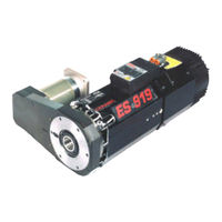
Sign In
Upload
Manuals
Brands
HSD Manuals
Tools
ES915
HSD ES915 Manuals
Manuals and User Guides for HSD ES915. We have
2
HSD ES915 manuals available for free PDF download: Instructions For Use Manual, Installation, Operation And Maintenance Manual
HSD ES915 Instructions For Use Manual (181 pages)
Brand:
HSD
| Category:
Tools
| Size: 4.32 MB
Table of Contents
Table of Contents
3
1 Preliminary Information
6
Documents Supplied with the Electrospindle
6
Purpose of the Manual
6
General Safety Symbols
6
Risks Associated with the Use of the Electrospindle
7
Risks Associated with Incorrect Use And/Or Operation
7
Specific Risks During Electrospindle Maintenance
8
Residual Risks
8
Purpose of the Product
8
Range of Applications
8
Identification of the Product and the Manufacturer
8
Glossary
9
Guarantee Conditions
10
2 Technical Specifications
11
Main Parts of Es915/Es919/Es929/Es988
11
Main Parts of Models Es884 - Es888
12
Main Parts of Model Es939
13
Variations with Vertical Mounting Plate
14
Variations with Military Connectors
15
Technical Cards Es884
16
Technical Cards Es888
18
Technical Cards Es915
20
Technical Cards Es919
26
Technical Cards Es929
40
Technical Cards Es939
44
Technical Cards Es983
52
3 Transport, Packaging, Unpacking, Storage
65
Warnings
65
Dimensions and Weights
65
Transport and Packaging Conditions
65
Unpacking Procedure
65
Storage
66
4 Installation and Initial Start-Up
67
Check
67
Preparation of the Auxiliary Systems of the Plant
67
Mechanical Connections
67
Positioning of Electrospindle (Versions with Electric Fan)
67
Electrospindle Resting Surface (Versions with Rectangular Framework)
68
Fixing Structure for Spindles with Round Framework
68
Tool Change System
69
Fixing Electrospindles with Rectangular Framework
70
Fixing Electrospindles with Round Framework
70
Threaded Bores for Accessories
70
Pneumatic Connections
71
Air Purity
71
Pneumatic Connection Points for Spindles with Single-Acting Cylinder
72
Variation with Vertical Block (Single-Acting Cylinder)
72
Pneumatic Connection Points ES939 or Variations with "T-Block" (Double-Acting Cylinder)
74
Pneumatic Connection Points for Spindles ES884 - ES888 (Single-Acting Cylinder)
76
Internal Volumes of the Pneumatic Cylinders
78
Internal Pressurisation
78
Cleaning the Tool-Holder Cone
78
Hydraulic Connections and Specifications of the Cooler
79
Specifications for the Cooler
79
Electrical Connections
80
Connectors
80
Military Connectors
83
Configurable Power Supply Terminal Board 220/380 V (Optional)
84
ES988 with Configurable Terminal Board 220/440 V (Optional)
85
Button for Manual Command of Tool Release
86
Electrical Layout for Tool-Holder Manual Release Circuit
86
5 General Checks after Installation
87
Checks before the Start-Up
87
Positioning
87
Pneumatic Connections
87
Electrical Connections
87
Programming the Inverter
87
Start-Up Checks
87
6 Use and Adjustment
88
Environmental Conditions
88
Running-In
88
Preheating
88
Electric Fan
88
Technical Characteristics of the Electric Fan
89
Tool-Holder Locking and Expulsion Device
89
Tool-Holder Cone
89
Installation of the Tie-Rod HSD 0804H0009 in the Cone ISO30 DIN69871
90
General Recommendations for the Tool-Holder Cones
90
Tool
90
Speed Limits
91
Maximum Speed and Shape of the Tool
91
What to Do if the Tool Is Blocked on the Piece Being Worked
111
Sensors
113
Technical Characteristics of the Inductive Sensors
113
Status Modes of the Electrospindle and Corresponding Outputs
114
Output of Sensor S3: "Shaft Idle" Signal
114
Use and Technical Characteristics of the Thermal Alarm
115
Encoder (Optional)
115
General Description
115
Technical Characteristics of the HSD Square Wave Encoder
116
Output of the HSD Square Wave Encoder
116
Technical Characteristics of the Lenord+Bauer Square Wave Encoder
117
Output of the Lenord+Bauer Square Wave Encoder
117
Technical Characteristics of the Lenord+Bauer Sinusoidal Encoder
118
7 Maintenance
124
Scheduled Maintenance
125
Checking the Cleaning of the Tool-Holder Cone and the Conical Housing in the Spindle Shaft
125
Purging the Filters of the Pneumatic Circuit
126
Protecting the Conical Seat in the Spindle Shaft
127
Cleaning the Tool-Holder Cone
127
Lubricating the HSK Collet
127
Checking the Connections
128
Replacing the Filters of the Pneumatic Circuit
128
Bearings
128
8 Replacing Components
129
Replacing the Electric Fan
129
Replacing the Shaft Kit for Models Es884, Es888
129
Disassembly Procedure
129
Assembly Procedure
131
Replacing the Shaft Kit for Models Es915,Es919,Es929,Es988
133
Disassembly Procedure
133
Assembly Procedure
138
Replacing the Shaft Kit for Models Es919 Encoder
142
Disassembly Procedure
142
Assembly Procedure
145
Replacing the Shaft Kit for Models Es939
148
Replacing the Shaft Kit for Models Es939 with Encoder
149
Cylinder Unit Disassembly
149
Disassembly of Shaft Kit and Phonic Wheel
151
Replacing the Encoder Readers
154
Replacing the HSD Optical Encoder Reader
154
Replacing the Sensors
158
Wiring the Sensors of ISO30 Models with Single-Acting Piston
158
Wiring the Sensors of HSK Models with Single-Acting Piston
158
Wiring the Sensors of ISO30 Models with Double-Acting Piston
159
Wiring the Sensors of HSK Models with Double-Acting Piston
159
Wiring the Sensors of HSK Models with Boosted Mounting Plate
160
Accessing the Sensors
161
Position of the Sensors
161
Accessing the ES939 Sensors
162
Position of the ES939 Sensors
162
Position of the Sensors in Models ES884/ES888
163
Description of the Sensor Unit
163
Replacing the Sensor Unit
164
Adjusting Sensor S1 (both ISO and HSK Versions)
165
Adjusting Sensor S2 in ISO Versions
166
Adjusting Sensor S2 in HSK Versions
167
Adjusting Sensor S3 (both ISO and HSK Versions)
167
Adjusting Sensor S4 (HSK Versions Only)
168
Kit of Gauges to Adjust Sensors S1 and S4 HSK F63 (Code HSD 3811H0110)
169
Kit of Gauges to Adjust Sensors S1 and S4 HSK E63 (Code HSD 3811H0739)
171
9 Optional Parts
173
Cooling with Forced Air
173
Installation of the Kit for Cooling with Forced Air
174
10 Troubleshooting
175
11 List of Spare Parts
179
12 Disposal
180
13 Customer Service
181
Advertisement
HSD ES915 Installation, Operation And Maintenance Manual (98 pages)
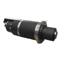
ELECTRO-SPINDLES for automatic tool changing, WHITH BELT DRIVEN C AXIS UNIT
Brand:
HSD
| Category:
Industrial Electrical
| Size: 2.22 MB
Table of Contents
Table of Contents
2
Documents Delivered with the Electro-Spindle
5
Document Information
5
Customer Assistance Service
5
Terms of Warranty
6
Warnings and Safety Precautions
7
Distribution of this Manual
7
General Safety Symbols
7
Risks Associated with the Electro-Spindle
8
Risks Associated with Improper Use and Handling
8
Risks Specific to Maintenance
9
General Information
9
Proper Use of the Product
9
Identification of Manufacturer and Part
10
Description of the Main Parts of the Electro-Spindle
11
Glossary
12
Technical Specifications
13
Available Models
13
Es915 / Es915 L
13
Es919 / Es919 L
13
Technical Specifications of ES915
14
Overall Dimensions of ES915
14
Specifications and Performance of ES915 2 Pole, 3.8 Kw Units
15
Specifications and Performance of ES915 4 Pole, 5 Kw Units
16
Technical Specifications of ES915 L
17
Overall Dimensions of ES915 L HSK F63 Long Nose
17
Specifications and Performance of ES915 L 4 Pole, 7.5 Kw Units
18
Technical Specifications of ES9
19
Overall Dimensions of ES919 ISO30 Short Nose
19
Overall Dimensions of ES919 ISO30 Long Nose
20
Overall Dimensions of ES919 HSK F63 Short Nose
21
Overall Dimensions of ES919 HSK F63 Long Nose
22
Specifications and Performance of ES919 2 Pole, 7 Kw Units
23
Specifications and Performance of ES919 2 Pole, 8 Kw Units
24
Specifications and Performance of ES919 4 Pole, 5.5 Kw Units
25
Specifications and Performance of ES919 4 Pole, 7.5 Kw Units
26
Technical Specifications of ES919 L
27
Overall Dimensions of ES919 L ISO30 Short Nose
27
Overall Dimensions of ES919 L ISO30 Long Nose
28
Overall Dimensions of ES919 L HSK F63 Short Nose
29
Overall Dimensions of ES919 L HSK F63 Long Nose
30
Specifications and Performance of ES919 L 4 Pole, 12 Kw Units
31
Technical Specifications of Belt Driven C Axis Unit
32
Overall Dimensions of ES919 ISO30 Short Nose with Belt Driven C Axis Unit
32
Overall Dimensions of Gear Units
33
Technical Specifications for Belt Driven C Axis Unit
34
Technical Specifications of Components
35
Bearings
35
Tool Holder Locking and Release Device
35
Automatic Cleaning of the Tool Holder and Internal Pressurization
36
Proximity Sensors
36
Tool Release Button
36
Thermal Switch
37
Cooling Fan
37
Transport and Moving
38
Storage
38
Lifting the Electro-Spindle in Its Crate
38
Installation
40
First Check
40
Preparation of the Equipment Required for Installation on Site
40
Mechanical Installation
40
The Supporting Surface
40
Positioning the Electro-Spindle
40
Mechanical Fixing of the Electro-Spindle
41
Threaded Service Holes
42
Compressed Air Connections
43
Compressed Air Unions
43
Functional Diagram of Electro-Spindle Compressed Air Connections
44
Cooling Circuit
45
Cooler Specifications
45
Electrical Connections
46
Connectors
46
Pin Layout of Fixed Signals Connector - ISO 30 Version
46
Pin Layout of Fixed Signals Connector - HSK F63 Version
47
Pin Layout of Fixed Power Connector
47
Tool Holder Release System Electrical Wiring Diagram for Electro-Spindles Not Controlled by CNC
48
Configurable Power Terminals (Optional)
49
General Checks after Installation and During Start-Up
50
Checking the Electro-Spindle before Start-Up
50
Checking the Electro-Spindle on First Start-Up
51
Operating the Electro-Spindle
52
Climatic Conditions
52
Running in
52
Warming up
52
Selecting the Tool Holder and Tool
53
ISO 30 Tool Holders
53
HSK F63 Tool Holders
54
General Safety Precautions for Tool Holders
55
Choosing Tools
56
Speed Limitations
57
Content of Graphs
57
Reading the Graphs
57
Es915 Iso30
58
ES919 ISO30 Short Nose , ES919 L ISO30 Short Nose
59
ES919 ISO30 Long Nose , ES919 L ISO30 Long Nose
60
ES919 HSK F63 Short Nose , ES919 L HSK F63 Short Nose
61
ES919 HSK F63 Long Nose , ES919 L HSK F63 Long Nose
62
Sensor Functioning
63
ISO 30 Versions
63
HSK F63 Versions
64
Thermal Switch
65
Maintenance
66
Scheduled Maintenance
67
Checking the Cleanliness of the Tool Holder Cone and of the Spindle Shaft Tool Housing
67
Cleaning the Tool Holder Cone
69
Protecting the Spindle Shaft's Conical Housing
69
Lubricating HSK Fingers
70
Bearings
70
Replacing Parts
71
Changing the Spindle Shaft Kit
72
Replacing the Cooling Fan
74
Replacing the Tool Change Push-Button
74
Replacing Sensors S1, S2, S3 and S4
75
Wiring of Sensors in HSK Versions
75
Wiring of Sensors in ISO 30 Versions
75
Accessing the Sensors
76
Location of Sensors
76
Replacing a Sensor Assembly
77
The Sensor Assembly
77
Calibrating Sensors S1, S2, and S3 on ISO 30 Electro-Spindles
78
Calibrating Sensors S1, S2, S3 and S4 on HSK F63 Electro-Spindles
78
Procedure for S1
78
Procedure for S2
78
Procedure for S3
79
Procedure for S4
79
(HSD Code 3811H0110)
80
Calibrating Sensors S1 and S4 on F63 HSK Electro-Spindles Using the 3811H0110 Kit80
80
Procedure for S1
81
Procedure for S4
81
Replacing the Cylinder Assembly
82
Accessories and Options
85
Spindle Shaft Stopped" Sensor S3
85
Bearing Temperature Sensor
85
Installing the Bearing Temperature Sensor
86
Characteristic Curve of the Temperature Sensor Referred to 1 Ma
86
C" Axis Unit
87
Belt Driven "C" Axis Unit
87
Gear Driven "C" Axis Unit
87
SC Sensor for the Belt Driven "C" Axis Unit
88
Replacing and Calibrating the SC Sensor in Belt Drive Versions
89
Forced Air Cooling
91
Installing the Forced Air Cooling Kit
91
Trouble Shooting
92
Spare Parts List
96
Disposing of the Electro-Spindle
97
Advertisement
Related Products
HSD ES884
HSD ES939
HSD ES888
HSD ES919
HSD ES983
HSD ES929
HSD ES988
HSD ES919 NC
HSD ES919 NL
HSD ES919 L NC
HSD Categories
Toy
Industrial Equipment
Medical Equipment
Monitor
Motorized Toy Car
More HSD Manuals
Login
Sign In
OR
Sign in with Facebook
Sign in with Google
Upload manual
Upload from disk
Upload from URL