Sign In
Upload
Manuals
Brands
Honda Manuals
Motorcycle
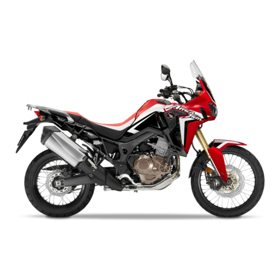
CRF1000 Africa Twin
Honda CRF1000 Africa Twin Manuals
Manuals and User Guides for Honda CRF1000 Africa Twin. We have
2
Honda CRF1000 Africa Twin manuals available for free PDF download: Shop Manual, Manual
Honda CRF1000 Africa Twin Shop Manual (574 pages)
Brand:
Honda
| Category:
Motorcycle
| Size: 28.81 MB
Table of Contents
Important Safety Precautions
2
How to Use this Manual
3
Symbols
4
Table of Contents
5
Service Rules
8
Abbreviations
8
Destination Code
8
Model Identification
9
Serial Numbers/Labels
9
General Specifications
11
PGM-FI System Specifications
12
Ignition System Specifications
12
Fuel System Specifications
12
Cooling System Specifications
13
Lubrication System Specifications
13
Cylinder Head/Valve/Camshaft Specifications
13
Dual Clutch Transmission Specifications (CRF100D)
14
Crankcase/Transmission/Balancer Specifications (CRF1000/A)
14
Clutch/Gearshift Linkage Specifications (CRF1000/A)
14
Alternator/Starter Clutch Specifications
14
Crankcase/Transmission/Balancer Specifications (CRF1000D)
15
Crankshaft/Piston/Cylinder Specifications
15
Front Wheel/Suspension/Steering Specifications
16
Rear Wheel/Suspension Specifications
16
Hydraulic Brake Specifications
16
Battery/Charging System Specifications
17
Lights/Meters/Switches Specifications
17
Engine & Frame Torque Values
18
Standard Torque Values
18
Fuel System Torque Values
20
Cooling System Torque Values
20
Lubrication System Torque Values
20
Cylinder Head/Valve/Camshaft Torque Values
20
Alternator/Starter Clutch Torque Values
21
Clutch/Gearshift Linkage (CRF1000/A) Torque Values
21
Dual Clutch Transmission (CRF1000D) Torque Values
22
Crankcase/Transmission/Balancer Torque Values
22
Front Wheels/Suspension/Steering Torque Values
23
Engine Removal/Installation Torque Values
23
Crankshaft/Piston/Cylinder Torque Values
23
Rear Wheel/Suspension Torque Values
24
Hydraulic Brake Torque Values
25
Anti-Lock Brake System (ABS) (CRF1000A/D) Torque Values
26
Lights/Meters/Switches Torque Values
26
Other Torque Values
26
Engine Lubrication and Seal Points
28
Frame Lubrication and Seal Points
29
Special Tool List
30
Cable and Harness Routing
32
Emission Control Systems
53
Source of Emissions
53
Crankcase Emission Control System
53
Exhaust Emission Control System
54
Noise Emission Control System
55
Technical Features
56
ABS with Mode-Selection Mechanism (Rear ABS off Mode) (CRF1000A/D)
56
G Ride (CRF1000D)
58
Dial Clutch Transmission Control Circuit (G Ride)
59
S Mode (CRF1000D)
60
D and S Mode Shift Timing
61
Frame/Body Panels/Exhaust System
63
Frame/Body Panels/Exhaust System - Service Information
64
Frame/Body Panels/Exhaust System Troubleshooting
64
Body Panel Locations
65
Main Seat Removal/Installation
66
Seat Catch Stay Removal/Installation
66
Seat Lock Cylinder Removal/Installation
66
Windscreen Removal/Installation
67
Knuckle Guard (CRF1000A/D) Removal/Installation
67
Middle Cowl Removal/Installation
68
Middle Cowl Disassembly/Assembly
68
Front Spoiler Removal/Installation
69
Front Cover Removal/Installation
69
Inner Panel Cover Removal/Installation
70
Inner Cover Removal/Installation
70
Tank Side Cover Removal/Installation
71
Tank Front Cover Removal/Installation
71
Front Fender Removal/Installation
71
Tank Rear Cover Removal/Installation
72
Skid Plate (CRF1000A/D) Removal/Installation
72
Left Rear Cover Removal/Installation
72
Pillion Seat Removal/Installation
73
ETC Tray Removal/Installation
73
Side Cover Removal/Installation
73
Rear Fender a Removal/Installation
74
Rear Carrier Removal/Installation
74
Side Cover Disassembly/Assembly
74
Rear Fender B Removal/Installation
75
Muffler Removal/Installation
78
Muffler Disassembly/Assembly
79
Exhaust Pipe Removal/Installation
79
Stud Bolt Replacement
80
Sidestand Removal/Installation
81
Maintenance
83
Maintenance Schedule
84
Fuel Line Maintenance
85
Throttle Operation
85
Air Cleaner Maintenance
86
Crankcase Breather Maintenance
87
Spark Plug Maintenance
87
Spark Plug Removal/Installation
88
Spark Plug Inspection
89
Valve Clearance
90
Intake Valve Clearance Adjustment
92
Engine Oil Level Inspection
93
Engine Oil Change
94
Engine Oil Filter
94
Clutch Oil Filter (CRF1000D)
95
Engine Idle Speed Inspection
96
Radiator Coolant
96
Cooling System Maintenance
97
Secondary Air Supply System Maintenance
97
Drive Chain Slack Inspection
98
Drive Chain Adjustment
98
Sprocket Inspection
99
Drive Chain Cleaning and Lubrication
99
Drive Chain Replacement
100
Drive Chain Slider
101
Brake Fluid
101
Brake Pads Wear Inspection
102
Brake System Mainenance
102
Hydraulic System Inspection
102
Brake Lever Adjustment
102
Brake Lock Operation (CRF1000D) Inspection and Adjustment
103
Brake Light Switch Maintenance
103
Headlight Aim
104
Clutch System (CRF1000/A) Maintenance
104
Sidestand Maintenance
105
Front Suspension Inspection
105
Front Suspension Adjustment
105
Rear Suspension Inspection
106
Rear Suspension Adjustment
106
Nuts, Bolts, Fasteners Maintenance
107
Steering Head Bearings Maintenance
108
Wheels/Tires Maintenance
108
PGM-FI System
109
PGM-FI System - Service Information
110
PGM-FI System Location
110
PGM-FI System Diagram
111
PGM-FI Troubleshooting Information
113
PGM-FI System Description
113
Dtc
113
MIL Blink Pattern
113
Erasing Stored DTC
114
Current Dtc/Freeze DTC
114
DTC Readout
114
MCS Information
114
Circuit Inspection
115
PGM-FI Symptom Troubleshooting
116
DTC Index Table
117
DTC Troubleshooting
119
DTC 1 (MAP Sensor)
119
DTC 7 (ECT Sensor)
122
DTC 7-2 (ECT Sensor High Voltage)
123
DTC 8 (TP Sensor)
124
DTC 8-2 (TP Sensor High Voltage)
126
DTC 9 (IAT Sensor)
127
DTC 11 (VS Sensor)
129
DTC 12/DTC 13 (Fuel Injector)
131
DTC 21 (O2 Sensor)
133
DTC 23 (O2 Sensor Heater)
135
Dtc 29 (Iacv)
137
Dtc 33-2 (Ecm/Pcm Eeprom)
138
DTC 54 (Bank Angle Sensor)
139
DTC 66 (Rear Wheel Speed Sensor Signal) (CRF1000A/D)
141
DTC 67 (Front Wheel Speed Sensor Signal) (CRF1000A/D)
143
DTC 83 (EOP Sensor) (CRF1000D)
144
DTC 84-1 (CPU in the PCM) (CRF1000D)
146
MIL Circuit Troubleshooting
147
ECM (CRF1000/A)/PCM (CRF1000D) Removal/Installation
147
Power/Ground Line Inspection
148
IAT Sensor Removal/Installation
149
ECT Sensor Removal/Installation
149
MAP Sensor Removal/Installation
149
VS Sensor Removal/Installation
150
O2 Sensor Removal/Installation
150
Bank Angle Sensor Removal/Installation
150
PGM-FI System Inspection
151
FI Relay Removal/Installation
151
FI Relay Inspection
152
Ignition System
153
Ignition System - Servie Information
154
Ignition System Troubleshooting
155
Ignition System Location
156
Ignition System Diagram
157
Ignition System Inspection
158
Ignition Coil Primary Peak Voltage
158
CKP Sensor Peak Voltage
159
Ignition Coil Tray Removal/Installation
161
Ignition Coil Tray Disassembly/Assembly
162
Ignition Timing
162
Electric Starter
163
Electric Starter - Service Information
164
Electric Starter Troubleshooting
164
Electric Starter Components Location
165
Electric Starter Diagram
166
Starter Motor Removal/Installation
167
Starter Motor Disassembly/Assembly
167
Starter Motor Inspection
168
Starter Relay Switch Removal/Installation
169
Starter Relay Switch Inspection
169
Neutral Diode (CRF1000/A) Removal/Installation
171
Neutral Diode (CRF1000/A) Inspection
171
Starter Relay (CRF1000D) Removal/Installation
171
Starter Relay (CRF1000D) Inspection
171
Fuel System
173
Fuel System - Service Information
174
Fuel System Troubleshooting
174
Fuel System Component Location
175
Quick Connect Fitting Removal/Installation
176
Fuel Pressure Relieving
176
Fuel Line Inspection
176
Fuel Pressure Normalization
177
Fuel Pressure Test
177
Fuel Flow Inspection
178
Fuel Tank Removal/Installation
178
Fuel Pump Unit Inspection
179
Fuel Pump Unit Removal
179
Fuel Pump Unit Disassembly/Inspection
180
Fuel Pump Unit Assembly
181
Fuel Pump Installation
182
Fuel Pump Relay Removal/Installation
182
Air Cleaner Housing Removal/Installation
183
Throttle Body Removal
184
Throttle Body Disassembly/Assembly
186
Throttle Body Installation
186
IACV Removal
188
IACV Inspection
188
IACV Installation
189
Fuel Injector Removal/Disassembly
189
Fuel Injector Assembly/Installation
190
Secondary Air Supply System Inspection
190
Pair Control Solenoid Valve Removal/Installation
191
Pair Control Solenoid Valve Inspection
191
Pair Reed Valve Removal/Installation
192
Pair Reed Valve Inspection
193
Cooling System
195
Cooling System - Service Information
196
Cooling System Troubleshooting
196
Cooling System Slow Pattern
197
Cooling System Testing
198
Radiator Cap/System Pressure Inspection
198
Coolant Replacement/Air Bleeding
198
Thermostat Removal/Installation
199
Thermostat Inspection
200
Radiator Removal/Installation
200
Radiator Disassembly/Assembly
203
Water Pump Removal/Installation
204
Water Pump Mechanical Seal Inspection
204
Radiator Reserve Tank Removal/Installation
204
Fan Control Relay Removal/Installation
205
Fan Control Relay Inspection
205
Lubrication System
207
Lubrication System - Service Information
208
Lubrication System Troubleshooting
208
Lubrication System Diagram
209
Oil Pressure Inspection
211
Oil Pump (CRF1000/A) Removal/Installation
211
Oil Pump (CRF1000/A) Disassembly/Assembly
212
Pressure Relief Valve Inspection
212
Oil Pump (CRF1000D) Removal/Installation
213
Oil Pump (CRF1000D) Disassembly/Assembly
213
Oil Pump Inspection
214
Oil Strainer Removal/Installation
214
Cylinder Head/Valve/Camshaft
217
Cylinder Head/Valve/Camshaft - Service Information
218
Cylinder Head/Valve/Camshaft Troubleshooting
218
Cylinder Head/Valve/Camshaft - Component Location
219
Cylinder Head Cover Removal
220
Cylinder Compression
220
Cylinder Head Cover Installation
221
Rocker Arm Removal
222
Rocker Arm Inspection
223
Rocker Arm Installation
223
Cam Chain Tensioner Lifter Removal/Installation
224
Cam Chain Tensioner Lifter Inspection
225
Camshaft Removal
225
Camshaft Inspection
226
Camshaft Installation
227
Cylinder Head/Valve/Camshaft
229
Cylinder Head Disassembly
230
Cylinder Head Inspection
231
Valve Guide Replacement
231
Valve Seat Inspection/Refacing
232
Cylinder Head/Valve/Camshaft Assembly
233
Insulator
235
Alternator/Starter Clutch
237
Alternator/Starter Clutch Troubleshooting
238
Alternator/Starter Clutch - Service Information
238
Alternator/Starter Clutch Component Location
239
Alternator Cover Removal/Installation (CRF1000/A)
240
Alternator Cover Removal/Installation (CRF1000D)
241
Stator/Ckp Sensor Removal/Installation
243
Flywheel Removal
243
Flywheel Inspection
244
Flywheel Installation
244
Starter Clutch Removal
245
Starter Clutch Inspection
246
Starter Clutch Installation
246
Clutch/Gearshift Linkage (Crf1000/A)
249
Clutch/Gearshift Linkage (CRF100/A) - Service Information
250
Clutch/Gearshift Linkage (CRF100/A) Troubleshooting
250
Clutch/Gearshift Linkage (CRF100/A) - Component Location
251
Right Crankcase Cover Removal
252
Clutch Lifter Lever
253
Right Crankcase Cover Inspection
254
Right Crankcase Cover Installation
254
Clutch Removal
256
Clutch Inspection
258
Clutch Pressure Plate Bearing Replacement
259
Clutch Outer Needle Bearing Replacement and Installation
260
Primary Drive Gear Removal
263
Primary Drive Gear Disassembly/Assembly
264
Primary Drive Gear Inspection
264
Primary Drive Gear Installation
264
Gearshift Linkage Removal
265
Gearshift Linkage Installation
267
Gearshift Linkage Inspection
267
Gearshift Pedal Removal/Installation
269
Dual Clutch Transmission (DCT) (CRF100D)
271
Dual Clutch Transmission (DCT) (CRF100D) - Service Information
272
For DCT System Troubleshooting
272
Shift Control Motor Function Procedures
272
Linear Solenoid Valve Function Procedures
272
DCT Symptom Troubleshooting
273
Excessive Noise or Vibration Around the DCT System
273
Dual Clutch Transmission (DCT) (CRF100D) Component Location
274
Dual Clutch Transmission (DCT) (CRF100D) Diagram
276
DCT Troubleshooting Information
277
DCT System Description
277
DTC Redout
278
Erasing DTC
279
DTC Index
280
DTC: Troubleshooting
285
DTC 9-1 (Clutch Line EOP Sensor Low Voltage)
285
DTC 9-2 (Clutch Line EOP Sensor High Voltage)
286
DTC 19-1 (CKP Sensor no Signal)
287
DTC 21-1 (Shift Spindle Angle Sensor Low Voltage)
288
DTC 21-2 (Shift Spindle Angle Sensor High Voltage)
290
DTC 22-1 (Shift Spindle Operation Malfunction: after Operating Gearshift Mechanism)
290
DTC 24-1 (Shift Control Motor Drive Circuit)
292
DTC 27-1 (Shift Drum Position Malfunction)
293
DTC 31-1 (Shift Control Motor Low Voltage)
294
DTC 32-1 (Fail Safe Relay Circuit Malfunction)
295
DTC 37-1 (Ignition Hold Relay Malfunction)
295
DTC 41-1 (N-D Switch Malfunction)
296
DTC 42-1 (Shift Switch Malfunction)
297
DTC 44-1 (EOT Sensor Low Voltage)
299
DTC 44-2 (EOT Sensor High Voltage)
300
DTC 47-1 or 48-1 (No.1 or No.2 Clutch EOP Sensor Low Voltage)
301
DTC 47-2 or 48-2 (No.1 or No.2 Clutch EOP Sensor High Voltage)
302
DTC 49-1, 49-2 (Clutch Line Low Pressure)
303
DTC 51-1 (TR Sensor Low Voltage)
304
DTC 51-2 (TR Sensor High Voltage)
306
DTC 52-1 (Neutral Switch Stuck Off)
306
DTC 52-2 (Neutral Switch Stuck On)
307
DTC 53-1 (Inner Mainshaft Sensor Speed Low)
307
DTC 54-1 (Outer Mainshaft Sensor Speed Low)
310
DTC 55-1, 55-2 (No.1 Linear Solenoid Valve)
312
DTC 56-1, 56-2 (No.2 Linear Solenoid Valve)
313
DTC 58-1 or DTC 59-1 (No.1 or No.2 Clutch Does Not Disengage When Shifting Gear)
314
DTC 61-1, 61-2, 61-3, 61-4, 62-1, 62-2 (No.1 Clutch Oil Pressure Malfunction)
315
DTC 63-1, 63-2, 63-3, 63-4, 64-1, 64-2 (No.2 Clutch Oil Pressure Malfunction)
315
DTC 65-1 (Front and Rear Wheel Speed Signal Malfunction)
316
DTC 69-1 (No.2 Clutch Operation Malfunction; Clutch Slips)
317
DTC 68-1 (No.1 Clutch Operation Malfunction; Clutch Slips)
317
Mode/Shift Indicator Circuit Troubleshooting
318
DTC 71-1, 72-1 (Inner, Outer Mainshaft/Countershaft Speed Ratio Failure)
318
DTC 84-1 (CPU in the PCM Malfunction)
318
A/M Switch Troubleshooting
319
Clutch Oil Feed Pipe Removal
320
Clutch Oil Feed Pipe Inspection
321
Clutch Oil Feed Pipe Installation
321
Removal of Right Crankcase Cover
322
Bearing Replacement
325
To Install the Right Crankcase Cover
325
Linear Solenoid Valve Removal
330
Linear Solenoid Valve Disassembly/Assembly
331
Linear Solenoid Valve Installation
331
Dual Clutch/Primary Driven Gear Removal
333
Dual Clutch/Primary Driven Gear Disassembly
333
Dual Clutch/Primary Driven Gear Inspection
335
Dual Clutch/Primary Driven Gear Assembly
336
Clutch Initial Clearance
338
Dual Clutch/Primary Driven Gear Installation
339
Primary Drive Gear Inspection
340
Shift Control Motor/Reduction Gears Removal
341
Shift Control Motor/Reduction Gears Installation
343
Gearshift Linkage - Removal
344
Gearshift Linkage Inspection/Installation
346
Inner Mainshaft Sensor Removal/Installation
348
Outer Mainshaft Sensor Removal/Installation
348
TR Sensor Removal/Installation
349
Shift Spindle Angle Sensor Removal/Installation
349
Clutch EOP Sensor Removal/Installation
350
EOT Sensor Removal/Installation
351
Neutral Switch Removal/Installation
352
Clutch Initialize Learning (PCM)
352
Crankcase/Transmission/Balancer
355
Crankcase/Transmission/Balancer Service Information
356
Crankcase/Transmission/Balancer Troubleshooting
357
Crankcase/Transmission/Balancer Component Location
358
Front Balancer
360
Rear Balancer
363
Crankcase Separation
367
Transmission Removal/Disassembly
369
Transmission Removal
371
Upper Crankcase Bearing Replacement
372
Transmission Assembly
374
Mainshaft (CRF1000/A) Exploded View
374
Mainshaft (CRF1000/D) Exploded View
375
Countershaft (CRF1000/A) Exploded View
376
Countershaft (CRF1000/D) Exploded View
377
Transmission Installation
378
Crankcase Assembly
381
Crankshaft/Piston/Cylinder
383
Crankshaft/Piston/Cylinder Service Information
384
Crankshaft/Piston/Cylinder Troubleshooting
384
Crankshaft/Piston/Cylinder Component Location
385
Crankshaft Side Clearance Inspection
386
Crankshaft Removal
386
Crankshaft Inspection
386
Crankshaft Installation
387
Main Journal Bearing Inspection
388
Main Journal Oil Clearance Inspection
388
Bearing Selection
389
Bearing Installation
390
Bearing Ispection
391
Oil Clearance Inspection
391
Piston/Cylinder
394
Piston/Connecting Rod Removal
394
Piston Removal
394
Piston Installation
395
Piston Ring Installation
395
Piston Inspection
395
Piston/Installation Rod Installation
396
Piston Oil Jet Removal/Installation
396
Engine Removal/Installation
397
Engine Removal/Installation - Service Installation
398
Engine Removal/Installation - Component Location
399
Engine Removal
401
Engine Installation
406
Front Wheel/Suspension/Steering
413
Front Wheel/Suspension/Steering Service Information
414
Front Wheel/Suspension/Steering Troubleshooting
414
Front Wheel/Suspension/Steering Component Location
415
Handlebar Removal
416
Handlebar Weight Removal/Installation
418
Handlebar Lower Holder Removal/Installation
419
Handlebar Installation
419
Front Wheel Removal
422
Front Wheel/Suspension/Steering
423
Front Wheel Disassembly/Assembly
424
Front Wheel Installation
426
Fork Removal
426
Fork Disassembly
427
Fork Inspection
430
Fork Assembly
430
Fork Installation
434
Steering Stem Removal
434
Bearing Replacement (Steering Stem)
436
Steering Stem Installation
438
Rear Wheel/Suspension
441
Rear Wheel/Suspension - Service Information
442
Rear Wheel/Suspension Troubleshooting
442
Rear Wheel/Suspension Component Location
443
Rear Wheel Removal
444
Rear Wheel Inspection
444
Rear Wheel Disassembly/Assembly
445
Rear Wheel Installation
447
Shock Absorber Inspection
448
Shock Absorber Removal/Installation
448
Cushion Linkage Removal
449
Cushion Disassembly/Inspection
449
Cushion Linkage Bearing Replacement
450
Cushion Assembly/Installation
451
Swingarm Removal
452
Swingarm Disassembly/Assembly
454
Swingarm Inspection
455
Pivot Bearing Replacement
455
Swingarm Installation
457
Hydraulic Brake
459
Hydraulic Brake - Service Information
460
Hydraulic Brake Troubleshooting
460
Hydraulic Brake Component Location
461
Brake Fluid Replacement/Air Bleeding
464
Brake Fluid Draining
464
Brake Fluid Filling/Air Bleeding
465
Brake Pad/Disc
466
Front Brake Pad Removal/Installation
466
Rear Brake Pad Removal/Installation
467
Parking Brake Pad/Pin Replacement (CRF1000D)
468
Brake Disc Inspection
470
Front Master Cylinder Removal/Installation
471
Front Master Cylinder Disassembly/Assembly
472
Front Master Cylinder Inspection
472
Rear Brake Pedal Removal/Installation
473
Rear Master Cylinder Removal/Installation
474
Rear Master Cylinder Disassembly/Assembly
475
Front Brake Caliper Removal/Installation
476
Rear Master Cylinder Inspection
476
Front Brake Caliper Disassembly/Assembly
477
Front Brake Caliper Inspection
477
Rear Brake Caliper Removal/Installation
478
Rear Brake Caliper Disassembly/Assembly
479
Rear Brake Caliper Inspection
479
Parking Brake Lever (CRF1000D) Removal
480
Parking Brake Lever Disassembly/Assembly
480
Parking Brake Caliper (CRF1000D) Removal/Installation
481
Parking Brake Lever Installation
481
Parking Brake Caliper (CRF1000D) Disassembly
482
Parking Brake Caliper (CRF1000D) Inspection
483
Parking Brake Caliper (CRF1000D) Assembly
483
Anti-Lock Brake System (ABS) (CRF1000A/D)
487
Anti-Lock Brake System (ABS) (CRF1000A/D) Service Information
488
Anti-Lock Brake System (ABS) (CRF1000A/D) Components Location
489
Anti-Lock Brake System (ABS) (CRF1000A/D) Diagram
490
ABS Troubleshooting Information
491
DTC Readout/Erasing Stored DTC
492
Inspection at ABS Modulator Connector
493
DTC Index (Anti-Lock Brake System (ABS) (CRF1000A/D))
494
ABS Indicator Circuit Troubleshooting
496
DTC Troubleshooting (Anti-Lock Brake System (ABS) (CRF1000A/D))
498
DTC 1-3, 1-4, 2-3, or 4-3 (Rear Wheelspeed Sensor Circuit/Rear Wheel Speed Sensor/Rear Pulser Ring/Rearwheel Lock)
500
DTC 1-5 (Front or Rear Wheel Speed Sensor Circuit: Short)
501
DTC 3-1, 3-2, 3-3 or 3-4 (Solenoid Valve)
502
DTC 5-1 or 5-4 (Pump Motor Lock/Power Supply Relay)
503
DTC 6-1 or 6-2 (Power Circuit)
504
DTC 7-1 (Tire Size)
504
DTC 8-1 (ABS Control Unit)
505
DTC 8-2 (Rear ABS off Indicator)
505
Wheel Speed Sensor Replacement
506
ABS Modulator Removal/Installation
510
Battery/Charging System
511
Battery/Charging System - Service Information
512
Battery/Charging System Troubleshooting
513
Battery/Charging System Component Location
514
Battery/Charging System Diagram
514
Battery Removal/Installation
515
Battery Box Removal/Installation
516
Voltage Inspection
516
Battery Testing
517
Charging System Inspection
517
Current Leakage Test
517
Charging Voltage Inspection
518
Regulator/Rectifier Removal/Installation
518
Regulator/Rectifier Inspection
518
Alternator Charging Coil Inspection
519
Ground Line Inspection
519
Battery Charging Line Inspection
519
Lights/Meters/Switches
521
Lights/Meters/Switches - Service Information
522
Lights/Meters/Switches - System Location
523
Headlight Removal/Installation
524
Headlight Troubleshooting
524
Headlight Relay Removal/Installation/Inspection
525
Turn Signal Light/Relay/Diode (CRF1000) Bulb Replacement
525
Turn Signal Light/Relay Removal/Installation
526
Turn Signal Light Removal/Installation
526
Turn Signal Light Inspection
527
Turn Signal Light Diode Removal/Installation/Inspection
528
Turn Signal Light/Relay (CRF1000A/D) Removal/Installation
528
Turn Signal Relay Removal/Installation/Inspection
529
License Light Bulb Replacement
531
Brake/Taillight Removal/Installation
531
Brake/Taillight Inspection
531
Combination Meter System Inspection
532
Combination Meter Removal/Installation
532
TXD Line Inspection
534
Combination Meter Digital Clock Set Procedure
535
Speedometer/Vs Sensor - System Inspection
536
VS Sensor Removal and Installation
536
Tachometer Inspection
536
Open Air Temperature Sensor Removal/Installation
537
Open Air Temperature Sensor Inspection
538
High Coolant Temperature Indicator/Ect Sensor Inspection
538
Engine Oil Pressure Indicator/Eop Switch (CRF1000/A)/EOP Sensor (CRF1000D) - System Inspection
539
EOP Sensor Removal/Installation (CRF1000D)
540
Fuel Level Sensor/Fuel Reserve Sensor - System Inspection
541
Parking Brake Indicator/Switch (CRF1000D) - System Inspection
542
Parking Brake Switch Inspection
542
Ignition Switch Inspection
543
Ignition Switch Removal/Installation
543
Handlebar Switches
543
Left Handlebar Switch Inspection
543
Right Handlebar Switch Inspection
544
Brake Light Switch
544
Clutch Switch (CRF1000/A)
545
Gear Position Switch (CRF1000/A) Removal/Installation
545
Gear Position Switch (CRF1000/A) Inspection
546
Sidestand Switch Removal/Installation
547
Sidestand Switch Inspection
547
Horn Removal/Installation
548
Horn Inspection
548
HSTC (Honda Selectable Torque Control) System Inspection
549
Rear ABS Switch (CRF1000A/D) Removal/Installation/Inspection
550
G Switch (CRF1000D) Removal/Installation/Inspection
551
Immobilizer System (HISS)
553
Immobilizer System (HISS) - Service Information
554
Immobilizer System (HISS) Location
554
Immobilizer System (HISS) Diagram
555
Key Registration Procedures
555
When the Ignition Switch Is Faulty
556
When All Keys Have Been Lost
557
When the ECM/PCM Is Faulty
558
Diagnostic Code Indication
559
Immobilizer System (HISS) Troubleshooting
560
ECM (CRF1000/A)/PCM (CRF1000D) - CKP Sensor Line Inspection
562
Hiss Indicator
562
Immobilizer Receiver
562
Power Input Line Inspection
563
Signal Line Inspection
563
Immobilizer Receiver
564
Replacement Parts for Problem (HISS)
564
Wiring Diagram
565
Wiring Diagram (CRF1000)
566
Wiring Diagram (CRF1000A)
567
Wiring Diagram (CRF1000D)
568
Index
570
Advertisement
Honda CRF1000 Africa Twin Manual (375 pages)
Brand:
Honda
| Category:
Motorcycle
| Size: 6.28 MB
Table of Contents
Table of Contents
6
Vehicle Safety
7
Safety Guidelines
8
Image Labels
12
Safety Precautions
17
Riding Precautions
18
Accessories & Modifications
22
Off-Road Safety
23
Loading
24
Operation Guide
25
Parts Location
25
Crf1100D/D2/D4 (P
30
Horn Button
123
Parking Brake
134
Audio System
155
Starting the Engine
211
Shifting Gears
213
Cruise Control
220
Accessory Socket
230
Maintenance
237
Importance of Maintenance
238
Maintenance Schedule
239
Maintenance Fundamentals
242
Tool
254
Components
255
Removing & Installing Body Components
255
Battery
255
Battery Box Cover
256
Clip
257
Front Seat
258
Rear Seat
260
Skid Plate
262
Tool Box
264
Engine Oil
265
Adding Engine Oil
266
Adding Coolant
271
Coolant
271
Changing Coolant
272
Brakes
273
Checking the Side Stand
277
Side Stand
277
Drive Chain
278
Adjusting the Drive Chain Slack
279
Wheels
282
Clutch
284
Adjusting the Clutch Lever
285
Throttle
287
Crankcase Breather
288
Other Adjustments
289
Adjusting the Headlight Aim
289
Adjusting the Brake Lever
290
Adjusting the Front Suspension
291
Adjusting the Rear Suspension
295
Adjusting the Windscreen Height
301
Troubleshooting
303
Engine will Not Start (HISS Indicator Stays On)
304
Overheating (Segment H Flashes in Coolant Temperature Gauge)
305
Warning Indicators on or Flashing
306
Low Oil Pressure Indicator
306
PGM-FI (Programmed Fuel Injection) Malfunction Indicator Lamp (MIL)
307
ABS (Anti-Lock Brake System) Indicator
308
Torque Control Indicator
309
If the “-” Indicator Is Blinking in the Gear
310
If the "-" Indicator Is Blinking in the Gear Position Window While Riding
310
Other Warning Indications
311
Fuel Gauge Failure Indication
311
Coolant Temperature Gauge Failure Indication
312
Handle Grip Heater Failure Indication
312
Tyre Puncture
313
Repair Kit
313
Front Wheel
315
Audio System Trouble
323
Electrical Trouble
336
Battery Goes Dead
336
Burned-Out Light Bulb
336
Blown Fuse
340
Information
344
Keys
345
Instruments, Controls, & Other Features
346
Caring for Your Vehicle
350
Storing Your Vehicle
354
Transporting Your Vehicle
355
You & the Environment
356
Serial Numbers
357
Fuels Containing Alcohol
358
Catalytic Converter
359
Specifications
364
Service Data
365
Torque Specifications
369
Index
370
Advertisement
Related Products
Honda Africa Twin CRF1000D
Honda Africa Twin CRF1000A
Honda Africa Twin CRF1000 2017
Honda Africa Twin CRF1000A 2017
Honda Africa Twin CRF1000D 2017
Honda CRF1000A 2018
Honda CRF1000D 2018
Honda CRF1000L
Honda CRF1000 2015
Honda CRF1000A 2015
Honda Categories
Motorcycle
Automobile
Lawn Mower
Offroad Vehicle
Engine
More Honda Manuals
Login
Sign In
OR
Sign in with Facebook
Sign in with Google
Upload manual
Upload from disk
Upload from URL