Sign In
Upload
Manuals
Brands
GE Manuals
Control Unit
MM3
GE MM3 Manuals
Manuals and User Guides for GE MM3. We have
2
GE MM3 manuals available for free PDF download: Instruction Manual
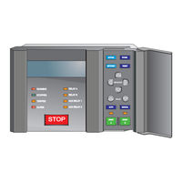
GE MM3 Instruction Manual (226 pages)
MOTOR MANAGER 3
Brand:
GE
| Category:
Control Unit
| Size: 4.83 MB
Table of Contents
Table of Contents
5
1 Introduction
11
Overview
11
Description
11
Features
11
Order Codes
13
Accessories
13
Technical Specifications
14
Mm3 Specifications
14
2 Installation
15
Description
17
Wiring
19
Typical Wiring Diagram
19
Inputs and Outputs
20
Overview
20
External Connections
20
H AUX 2 COIL (34/35)
21
K SWITCH INPUTS (1 - 16)
22
Stop (11)
25
User Interface
25
Description
25
Message Display
25
Indicator Leds
26
Keypad
27
Setpoints Key
27
Actual Values Key
27
Store Key
28
Stop Key
28
Reset Key
28
Start a Key
28
Start B Key
28
Message Up/Down Keys
29
Message Left/Right Keys
29
Value Up/Down Keys
29
Hardware Description
30
Mm3 Design
30
4 Setpoints
31
Overview
31
Description
31
Setpoint Message Abbreviations
31
Setpoints Message Summary
32
S1 Configuration
33
Description
33
Communications
33
Motor Identification
34
Starter
34
Ct/Vt Inputs
36
Thermistor
37
Fault Mode
37
Statistics
38
Programmable Message
38
Preferences
38
S2 Protection
39
Description
39
Motor Protection - Thermal
39
Motor Protection - Ground Fault
41
Motor Protection - Options
43
Load Protection
45
Under/Overvoltage Protection
47
S3 Process
48
Description
48
Programmable Inputs
49
Interlock Names
53
Stop Configuration
54
Analog Input
54
Process Options
56
S4 Control
57
Description
57
Undervoltage Auto Restart
57
Aux 1/2 Relay Config
58
S5 Monitoring
61
Description
61
Plant Condition
61
Preset Counters and Timers
62
S6 Factory Data
63
Description
63
Product Firmware Identification
63
Product Model Identification
64
Factory Service Data
64
Mm3 Standard Overload Curves
65
Overload Curve Trip Times
65
Nema Compatible Overload Curves
67
Nema Curve Trip Times
67
S7 Testing
69
Description
69
Test Configuration
69
Test Relays and Leds
70
Current Simulation
71
Analog Output Simulation
72
Analog Input Simulation
73
Switch Inputs Simulation
74
Thermistor Simulation
76
5 Actual Values
77
Overview
77
Description
77
Default Message Selection
77
Actual Values Message Abbreviations
78
Actual Values Message Summary
78
Actual Values Messages
79
A1 Data
79
Description
79
Motor Data
79
Process Data
80
Programmable Message
80
A2 Status
81
Description
81
Trip Data
81
Alarm Data
82
Motor Status
84
A3 Inputs
85
Description
85
Input Contacts Status
85
A4 Statistics
87
Description
87
Timers
87
Counters
87
6 Communications
89
Mm3 Modbus Protocol
89
Overview
89
Electrical Interface
89
Data Frame Format and Data Rate
89
Data Packet Format
90
Error Checking
90
Crc-16 Algorithm
91
Timing
91
Mm3 Supported Functions
92
Description
92
Function Code 01H
92
Function Code 03H
93
Function Code 04H
94
Function Code 05H
95
Function Code 06H
96
Function Code 07H
97
Function Code 08H
98
Function Code 10H
99
Error Responses
100
Description
100
Applications
101
Performing Commands Using Function Code 10H
101
Storing Communications Address Using the Broadcast Command
102
Using the User Definable Memory Map
103
User Definable Memory Map Default Values
104
Memory Map
106
Memory Map Table
106
Description
106
Data Formats Table
125
7 Testing
133
Injection Testing
133
Primary Injection Testing
133
Secondary Injection Testing
133
Functional Tests
134
Phase Current Functions
134
Unbalance Examples
135
Example #1
135
Example #2
135
Ground Fault Current Functions
135
Input Functions
136
Thermistor Input Tests
136
Power Fail Test
136
8 Mm3Pc Software
137
Overview
137
Description
137
Hardware & Software Requirements
137
Checking if Installation/Upgrade Is Required
138
Installing Mm3Pc
139
Software Installation/Upgrade
139
Configuration
140
Configuring Mm3Pc
140
Mm3Pc Program Menus
141
Using Mm3Pc
142
Saving Setpoints to a File
142
Mm3 Firmware Upgrades
143
Loading Setpoint Files
144
Entering Setpoints
145
Viewing Actual Values
146
Chassis Mount Units
148
Description
148
Setting the Baud Rate and Parity
148
9 Starter Types
151
Fv Non-Reversing Starter
151
Description
151
Mm3 Sequences
151
Fv Reversing Starter
153
Description
153
Mm3 Sequences
154
Description
156
Mm3 Sequences
157
Description
161
Mm3 Sequences
162
Description
164
Mm3 Sequence
165
Description
167
Description
169
Mm3 Sequences
170
Description
173
Mm3 Sequences
174
Description
177
Description
178
Mm3 Sequences
179
Description
181
Mm3 Sequence
182
Description
184
Description
186
Control Operation
189
Wire Hand / 2-Wire Auto
191
Wire Hand / 2-Wire Auto
193
Wire Hand / 3 Wire Auto
195
Wire Hand / 2-Wire Auto
197
A.1.1 Description
199
B.1.1 Questions and Answers
203
C.1.1 Checklist
205
D SWITCH INPUTS
206
D.1.1 Overview
207
E.1.1 Mm3 Ct Withstand
209
F.1.1 List of Tables
213
H.1.1 Ge Power Management Warranty
217
Advertisement
GE MM3 Instruction Manual (230 pages)
Brand:
GE
| Category:
Relays
| Size: 6.42 MB
Table of Contents
Table of Contents
3
Description
9
Features
9
Order Codes
13
Accessories
13
Technical Specifications
14
Protection
14
Inputs
15
Outputs
15
Communications
16
Conformance
16
Description
19
Wiring
20
Typical Wiring
20
Inputs and Outputs
21
Phase Ct Inputs
21
Ground Fault Ct Input
21
Supply Voltage
21
Ground Surge
21
External Connections
21
Thermistor Input
21
Analog Input
22
Analog Output
22
Auxiliary 2 Coil
22
2.3.10 Output Relays
22
Serial Communication Port
22
2.3.12 Switch Inputs
23
Programmable Switch Inputs
23
2.3.14 Stop
23
Start Aand Startb
23
Local Isolator no
24
Contactor Status
24
Dielectric Strength Testing
24
Starter Types
25
Full-Voltage Non-Reversing Starter
25
Full-Voltage Reversing Starter
27
Two-Speed Starter
29
Slip Ring Starter
34
Primary Resistance Starter
36
Inverter Starter
38
Autotransformer Open Transition Starter
39
Autotransformer Closed Transition Starter
44
Part Winding Starter
47
Wye-Delta Open Transition Starter
48
Wye-Delta Closed Transition Starter
50
Duty/Standby Starter
52
2.4.13 Soft Starter
54
Description
57
Message Display
57
Indicator Leds
58
Keypad
60
Setpoints Key
60
Actual Values Key
60
Store Key
60
Stop Key
61
Reset Key
61
Start A/B Keys
61
Message Up/Down Keys
61
Message Left/Right Keys
61
Value Keys
61
Hardware Description
62
Mm3 Motor Manager 3 Design
63
Description
63
Requirements
64
Checking if Installation/Upgrade Is Required
64
Installing Ener Vista Mm3 Setup
64
Configuration
67
Serial Communications
67
Ethernet Communications
69
Using Enervista Mm3 Setup
70
Saving Setpoints to a File
70
Firmware Upgrades
71
Loading Setpoint Files
72
Entering Setpoints
73
Viewing Actual Values
74
Chassis Mount Units
77
Description
77
Setting the Baud Rate and Parity
77
Setpoints Main Menu
81
Description
83
Setpoint Message Abbreviations
84
S1 Configuration
85
Communications
85
Motor Identification
85
Starter
86
Ct/Vt Inputs
87
Thermistor
88
Fault Mode
89
Statistics
89
Programmable Message
90
Preferences
90
S2 Protection
91
Motor Protection : Thermal
91
Motor Protection : Ground Fault
96
Motor Protection: Options
97
Load Protection
99
Under /Overvoltage Protection
101
S3 Process
102
Programmable Inputs
102
Interlock Names
107
Stop Configuration
107
Analog Input
108
Analog Output
109
Process Options
110
S4 Control
111
Undervoltage Auto Restart
111
Auxiliary Relay Configuration
112
S5 Monitoring
115
Plant Condition
115
Preset Counters and Timers
116
S6 Factory Data
117
Product Firmware Identification
117
Product Model Identification
117
Factory Service Data
117
S7 Testing
118
Test Configuration
118
Test Relays and Led S
118
Current Simulation
119
Analog Output Simulation
120
Analog Input Simulation
121
Switch Inputs Simulation
121
Thermistor Simulation
122
Actual Values Main Menu
125
Default Message Selection
126
Actual Values Abbreviations
126
A1 Data
127
Motor Data
127
Process Data
128
Programmable Message
129
A2 Status
130
Trip Data
130
Alarm Data
131
Motor Status
134
A3 Inputs
136
Input Contacts Status
136
A4 Statistics
137
Timers
137
Counters
137
Primary Injection Testing
139
Secondary Injection Testing
139
Functional Tests
141
Phase Current Functions
141
Unbalance Examples
142
Ground Fault Current Functions
143
Input Functions
143
Thermistor Input Tests
143
Power Fail Test
144
Overview
145
Electrical Interface
145
Data Frame Format and Data Rate
146
Data Packet Format
146
Error Checking
147
Timing
148
Supported Modbus Functions
149
Description
149
Function Code 01H
149
Function Code 03H
150
Function Code 04H
150
Function Code 05H
151
Function Code 06H
152
Function Code 07H
152
Function Code 08H
154
Function Code 10H
154
Error Responses
155
Applications
156
Performing Commands Using Function Code 10H
156
Storing Addresses Using the Broadcast Command
156
Using the User-Definable Memory Map
157
Modbus Memory Map
160
Description
160
Modbus Data Formats
187
Two-Wire Control
199
HOA Two-Wire Hand / Two- Wire Auto
200
HOA Three- Wire Hand / Two-Wire Auto
202
HOA Three- Wire Hand / Three-Wire Auto
203
HA Three-Wire Hand / Two- Wire Auto
204
10: Miscellaneous Asymmetrical Starting Current
209
10.2 CT Isolation
210
Mm3 Motor Manager
210
10.3 MM3 Motor Manager 3 FAQ
213
Frequently Asked Questions
213
10.4 Installation Checklist
215
10.4.1 Overview
215
Grounding of Phase and Ground Cts
215
Rs485 Communications Port
215
10.4.5 Switch Inputs
216
Thermistor and Analog Inputs
216
Stop Switch Input
216
Contactor Status Feedback
216
10.5 EU Declaration of Conformity
217
10.5.1 EU Declaration
217
10.6 Change Notes
218
Revision History
218
10.7 GE Multilin Warranty
219
Warranty Statement
219
Advertisement
Related Products
GE MASTR-2 C-500 Series
GE Mini COM Express 10
GE mCOM10-L1500
GE MOTOR MANAGER 3
GE DewPro MMY30
GE DewPro MMY31
GE Multilin MM300
GE MM200
GE DewPro MMY 245
GE Match 3000
GE Categories
Refrigerator
Ranges
Microwave Oven
Air Conditioner
Dishwasher
More GE Manuals
Login
Sign In
OR
Sign in with Facebook
Sign in with Google
Upload manual
Upload from disk
Upload from URL