Sign In
Upload
Manuals
Brands
Fronius Manuals
AC Power Distribution
TransPuls Synergic 4000
Fronius TransPuls Synergic 4000 Manuals
Manuals and User Guides for Fronius TransPuls Synergic 4000. We have
2
Fronius TransPuls Synergic 4000 manuals available for free PDF download: Operating Instructions Manual, Operating Instructions & Spare Parts
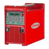
Fronius TransPuls Synergic 4000 Operating Instructions Manual (212 pages)
MIG/MAG power source
Brand:
Fronius
| Category:
Welding Accessories
| Size: 5.44 MB
Table of Contents
Parameters for Operating Power Sources in Parallel in the Setup Menu Level
2
Parameters for Timetwin Digital in the Setup Menu Level
2
Parameters for TIG Welding in the Setup Menu Level
2
Parameters for Rod Electrode (MMA) Welding in the Setup Menu Level
2
Table of Contents
3
Safety Rules
9
Explanation of Safety Notices
9
General
9
Proper Use
9
Environmental Conditions
10
Obligations of the Operator
10
Obligations of Personnel
10
Mains Connection
10
Protecting Yourself and Others
11
Noise Emission Values
11
Danger from Toxic Gases and Vapours
12
Danger from Flying Sparks
12
Risks from Mains Current and Welding Current
13
Meandering Welding Currents
14
EMC Device Classifications
14
EMC Measures
14
EMF Measures
15
Specific Hazards
15
Requirement for the Shielding Gas
16
Danger from Shielding Gas Cylinders
16
Danger from Escaping Shielding Gas
17
Safety Measures at the Installation Location and During Transport
17
Safety Measures in Normal Operation
17
Commissioning, Maintenance and Repair
18
Safety Inspection
18
Disposal
19
Safety Symbols
19
Data Protection
19
Copyright
19
General Information
21
General
23
Device Concept
23
Functional Principle
23
Application Areas
23
Warning Notices on the Device
24
Description of Warning Notices on the Device
25
Special Versions
27
General
27
Alu Edition
27
Crni Edition
27
CMT Variants
27
CMT 4000 Advanced
28
TIME 5000 Digital
28
Yard Edition
28
Steel Edition
28
System Components
29
General
29
Overview
29
Control Elements and Connections
31
Description of the Control Panels
33
General
33
Safety
33
Overview
33
Standard Control Panel
34
General
34
Key Combinations - Special Functions
36
Displaying the Feeder Inching Speed
36
Displaying the Gas Pre-Flow and Gas Post-Flow Time
36
Displaying the Software Version
37
Comfort / Crni / Steel Control Panel
38
Difference between Comfort, Crni and Steel Control Panels
38
Comfort Control Panel
38
Key Combinations - Special Functions
42
Displaying the Feeder Inching Speed
42
Displaying the Gas Pre-Flow and Gas Post-Flow Time
43
Displaying the Software Version
43
US Control Panel
44
Key Combinations - Special Functions
47
Displaying the Feeder Inching Speed
47
Displaying the Gas Pre-Flow and Gas Post-Flow Time
48
Displaying the Software Version
48
TIME 5000 Digital Control Panel
49
Key Combinations - Special Functions
52
Displaying the Feeder Inching Speed
53
Displaying the Gas Pre-Flow and Gas Post-Flow Time
53
Displaying the Software Version
53
CMT Control Panel
54
Key Combinations - Special Functions
57
Displaying the Feeder Inching Speed
57
Displaying the Gas Pre-Flow and Gas Post-Flow Time
57
Displaying the Software Version
58
Yard Control Panel
59
Key Combinations - Special Functions
62
Displaying the Feeder Inching Speed
62
Displaying the Gas Pre-Flow and Gas Post-Flow Time
63
Displaying the Software Version
63
Remote" Control Panel
64
General
64
CMT Remote Control Panel
65
General
65
CMT Remote and CMT Advanced Control Panel
65
Connections, Switches and Mechanical Components
66
TPS 2700 Power Source
66
TPS 2700 CMT Power Source
67
TS 4000 / 5000, TPS 3200 / 4000 / 5000, TIME 5000 Digital Power Sources
68
CMT 4000 Advanced Power Source
69
Installation and Commissioning
71
Minimum Equipment Needed for Welding Task
73
General
73
MIG/MAG Gas-Cooled Welding
73
MIG/MAG Water-Cooled Welding
73
MIG/MAG Automated Welding
73
CMT Manual Welding
73
CMT Automated Welding
74
CMT Advanced Welding
74
TIG DC Welding
74
Manual Metal Arc Welding
74
Before Installation and Commissioning
75
Safety
75
Proper Use
75
Setup Regulations
75
Mains Connection
75
Connecting up the Mains Cable on US Power Sources
77
General
77
Stipulated Mains Cables and Strain-Relief Devices
77
Safety
77
Connecting the Mains Cable
77
Replacing the Strain-Relief Device
79
Start-Up
80
Safety
80
Remarks on the Cooling Unit
80
Information on System Components
80
Overview
81
Commissioning the TPS 2700
82
General
82
Recommendation for Water-Cooled Applications
82
Connecting the Gas Cylinder
82
Establishing a Ground (Earth) Connection
83
Connecting the Welding Torch
83
Inserting/Replacing Feed Rollers
84
Inserting the Wirespool
84
Inserting the Basket-Type Spool
85
Feeding in the Wire Electrode
86
Setting the Contact Pressure
87
Adjusting the Brake
87
Design of the Brake
88
Commissioning the TS 4000 / 5000, TPS 3200 / 4000 / 5000, TIME 5000 Digital
89
General
89
Fitting the System Components (Overview)
89
Fixing the Strain-Relief Device in Place
90
Connecting the Interconnecting Hosepack
90
Connecting the Gas Cylinder
91
Establishing a Ground (Earth) Connection
92
Connecting the Welding Torch
92
Other Tasks
92
Commissioning the CMT4000 Advanced
93
Fitting the System Components (Overview)
93
Connecting the Interconnecting Hosepack, CMT Welding Torch and Wire Buffer
93
Other Tasks
94
Preparing the Wire-Feed Unit
94
Welding
95
MIG/MAG Modes
97
General
97
Symbols and Their Explanations
97
2-Step Mode
98
Special 4-Step Mode
99
Spot Welding
99
MIG/MAG Welding
100
Safety
100
General Tasks before MIG/MAG Welding
100
Overview
100
MIG/MAG Synergic Welding
101
General
101
Corrections During Welding
102
Adjusting Parameters for Correction
103
Remarks on the Standard Control Panel
103
MIG/MAG Standard Manual Welding
104
General
104
Available Parameters
104
Corrections During Welding
105
Adjusting Parameters for Correction
106
CMT Welding
107
General
107
Corrections During Welding
108
Adjusting Parameters for Correction
110
Special Functions and Options
111
Arc Break Watchdog Function
111
Ignition Time-Out Function
111
Spatter-Free Ignition Option
111
Synchropulse Option
112
Robot Welding
114
Prerequisite
114
General
114
Special 2-Step Mode for Robot Interface
114
Wire-Stick Control Function
115
Changing the Welding Process During CMT Advanced Welding
115
TIG Welding
116
Safety
116
Prerequisite
116
Preparation
116
TIG Welding
117
Igniting the Arc
117
Finishing Welding
118
TIG Comfort Stop Option
118
TIG Welding with TIG Comfort Stop
119
MMA Welding
121
Safety
121
Prerequisite
121
Preparation
121
Manual Metal Arc Welding
122
Corrections During Welding
122
Adjusting Parameters for Correction
123
Hotstart Function
123
Softstart Function
123
Anti-Stick Function
124
Job Mode
125
General
125
Prerequisites
125
Restrictions
125
Job Mode Displays on the Left-Hand Digital Display
125
Selecting Job Mode as the Process
125
Creating a Job
126
Retrieving a Job
127
Copying/Overwriting a Job
128
Deleting a Job
129
Setup Settings
131
Job Correction
133
General
133
Opening the Job Correction Menu
133
Changing Welding Parameters
133
Exiting the Job Correction Menu
133
Parameters in the Job Correction Menu
134
Permanently Settable Parameters
134
Parameters that Can be Corrected at a Later Time
137
Shielding Gas Setup Menu
139
General
139
Protective Gas Shield Setup Menu for the Standard Control Panel
139
Protective Gas Shield Setup Menu for the Comfort, US, TIME 5000 Digital and CMT Control Panels
139
Welding Parameters in the Protective Gas Shield Setup Menu
139
Setup Menu for the Standard Control Panel
141
General
141
Parameters in the Setup Menu for the Standard Control Panel
141
Process Setup Menu
144
General
144
Process Setup Menu for the Comfort, US, TIME 5000 Digital and CMT Control Panels
144
Parameters for MIG/MAG Welding in the Process Setup Menu
144
Parameters for TIG Welding in the Process Setup Menu
147
Parameters for MMA Welding in the Process Setup Menu
147
Mode Setup Menu
149
General
149
Mode Setup Menu for the Comfort, US, TIME 5000 Digital and CMT Control Panels
149
Welding Parameters for "Special 2-Step Mode" in the Mode Setup Menu
149
Welding Parameters for "Special 4-Step Mode" in the Mode Setup Menu
150
Parameters for Spot Welding in the Mode Setup Menu
151
Setup Menu - Level 2
152
General
152
Setup Menulevel 2 for the Standard Control Panel
152
Setup Menu Level 2 for the Comfort, US, TIME 5000 Digital and CMT Control Panels
153
Parameters for MIG/MAG Welding in the Setup Menu Level
153
Notes on the Use of the FAC Parameter
161
Calibrating Push-Pull Unit
162
General
162
Calibrating the Push-Pull Unit - Overview
162
Calibrating the Push-Pull Unit
163
Service Codes for Push-Pull Calibration
167
Safety
167
Service Codes When the Drive Units Are Disengaged ("Open-Circuit" Calibration)
167
Service Codes When the Drive Units Are Engaged ("Engaged" Calibration)
168
Measuring Welding Circuit Resistance R
170
General
170
Displaying Welding Circuit Inductivity L
172
General
172
Arranging the Interconnecting Hosepack Correctly
172
Troubleshooting and Maintenance
173
Troubleshooting
175
General
175
Safety
175
Displayed Service Codes
175
Power Source - Troubleshooting
183
Care, Maintenance and Disposal
187
General
187
Safety
187
At Every Start-Up
187
Every 2 Months
187
Every 6 Months
187
Disposal
187
Appendix
189
Technical Data
191
Special Voltages
191
Tps 2700
191
Tps 2700 MV
192
Tps 3200
193
Tps 3200 MV
194
Tps 3200 460 V Ac
195
Ts/Tps 4000
196
Ts/Tps 4000 MV
197
Ts/Tps 5000
198
Ts/Tps 5000 MV
199
Technical Data - US Devices
200
Technical Data - Alu Edition, Crni Edition, Yard Edition and CMT Variants
200
TIME 5000 Digital
200
CMT 4000 Advanced
201
CMT 4000 Advanced MV
202
Welding Program Databases
204
Explanation of Symbols
204
Setting up a Welding Program Database - Example
204
Terms and Abbreviations Used
205
General
205
Terms and Abbreviations a - C
205
Terms and Abbreviations D - F
205
Terms and Abbreviations G - I
206
Terms and Abbreviations J - R
207
Terms and Abbreviations S
207
Terms and Abbreviations T - 2Nd
208
Advertisement
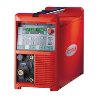
Fronius TransPuls Synergic 4000 Operating Instructions & Spare Parts (212 pages)
MIG/MAG Power source
Brand:
Fronius
| Category:
AC Power Distribution
| Size: 27.06 MB
Table of Contents
Table of Contents
5
Safety Rules
11
Explanation of Safety Symbols
11
General
11
Intended Purpose
12
Environmental Conditions
12
Obligations of the Operator
12
Obligations of Personnel
13
Mains Connection
13
Protecting Yourself and Others
13
Noise Emission Values
14
Danger from Toxic Gases and Vapours
14
Danger from Flying Sparks
15
Risks from Mains Current and Welding Current
15
Meandering Welding Currents
17
EMC Device Classifications
17
EMC Measures
17
EMF Measures
18
Specific Hazards
18
Danger from Shielding Gas Cylinders
20
Safety Measures at the Installation Location and During Transport
20
Safety Measures in Normal Operation
21
Maintenance and Repair
22
Safety Inspection
22
Disposal
22
Safety Symbols
22
Data Protection
23
Copyright
23
General Information
25
General
27
Device Concept
27
Functional Principle
27
Application Areas
27
Warning Notices on the Device
27
Special Versions
29
General
29
Alu Edition
29
Crni Edition
29
CMT Variants
29
CMT 4000 Advanced
29
TIME 5000 Digital
30
Yard Edition
30
Steel Edition
30
System Components
31
General
31
Overview
31
Control Elements and Connections
33
Description of the Control Panels
35
General
35
Safety
35
Overview
35
Standard Control Panel
36
General
36
Key Combinations - Special Functions
38
Displaying the Feeder Inching Speed
38
Displaying the Gas Pre-Flow and Gas Post-Flow Time
38
Displaying the Software Version
38
Comfort / Crni / Steel Control Panel
40
Difference between Comfort, Crni and Steel Control Panels
40
Comfort Control Panel
40
Key Combinations - Special Functions
43
Displaying the Feeder Inching Speed
43
Displaying the Gas Pre-Flow and Gas Post-Flow Time
44
Displaying the Software Version
44
US Control Panel
45
Key Combinations - Special Functions
48
Displaying the Feeder Inching Speed
48
Displaying the Gas Pre-Flow and Gas Post-Flow Time
48
Displaying the Software Version
49
TIME 5000 Digital Control Panel
50
Key Combinations - Special Functions
53
Displaying the Feeder Inching Speed
53
Displaying the Gas Pre-Flow and Gas Post-Flow Time
54
Displaying the Software Version
54
CMT Control Panel
55
Key Combinations - Special Functions
58
Displaying the Feeder Inching Speed
58
Displaying the Gas Pre-Flow and Gas Post-Flow Time
58
Displaying the Software Version
58
Yard Control Panel
60
Key Combinations - Special Functions
63
Displaying the Feeder Inching Speed
63
Displaying the Gas Pre-Flow and Gas Post-Flow Time
63
Displaying the Software Version
64
Remote" Control Panel
65
General
65
CMT Remote Control Panel
66
General
66
CMT Remote and CMT Advanced Control Panel
66
Connections, Switches and Mechanical Components
67
TPS 2700 Power Source
67
TPS 2700 CMT Power Source
68
TS 4000 / 5000, TPS 3200 / 4000 / 5000, TIME 5000 Digital Power Sources
69
CMT 4000 Advanced Power Source
70
Installation and Commissioning
73
Minimum Equipment Needed for Welding Task
75
General
75
MIG/MAG Gas-Cooled Welding
75
MIG/MAG Water-Cooled Welding
75
MIG/MAG Automated Welding
75
CMT Manual Welding
75
CMT Automated Welding
76
CMT Advanced Welding
76
TIG DC Welding
76
Manual Metal Arc Welding
76
Before Installation and Commissioning
77
Safety
77
Proper Use
77
Setup Regulations
77
Mains Connection
77
Connecting up the Mains Cable on US Power Sources
78
General
78
Stipulated Mains Cables and Strain-Relief Devices
78
Safety
78
Connecting the Mains Cable
78
Replacing the Strain-Relief Device
79
Start-Up
81
Safety
81
Remarks on the Cooling Unit
81
Information on System Components
81
Overview
81
Commissioning the TPS 2700
82
General
82
Recommendation for Water-Cooled Applications
82
Connecting the Gas Cylinder
82
Establishing a Ground (Earth) Connection
83
Connecting the Welding Torch
83
Inserting/Replacing Feed Rollers
83
Inserting the Wirespool
84
Inserting the Basket-Type Spool
84
Feeding in the Wire Electrode
85
Setting the Contact Pressure
86
Adjusting the Brake
86
Design of the Brake
87
Commissioning the TS 4000 / 5000, TPS 3200 / 4000 / 5000, TIME 5000 Digital
88
General
88
Fitting the System Components (Overview)
88
Fixing the Strain-Relief Device in Place
89
Connecting the Interconnecting Hosepack
89
Connecting the Gas Cylinder
90
Establishing a Ground (Earth) Connection
91
Connecting the Welding Torch
91
Other Tasks
91
Commissioning the CMT4000 Advanced
92
Fitting the System Components (Overview)
92
Connecting the Interconnecting Hosepack, CMT Welding Torch and Wire Buffer
92
Other Tasks
92
Preparing the Wire-Feed Unit
93
Welding
95
MIG/MAG Modes
97
General
97
Symbols and Their Explanations
97
2-Step Mode
98
Special 4-Step Mode
99
Spot Welding
99
MIG/MAG Welding
100
Safety
100
General Tasks before MIG/MAG Welding
100
Overview
100
MIG/MAG Synergic Welding
101
General
101
Corrections During Welding
102
Adjusting Parameters for Correction
102
Remarks on the Standard Control Panel
102
MIG/MAG Standard Manual Welding
103
General
103
Available Parameters
103
Corrections During Welding
104
Adjusting Parameters for Correction
104
CMT Welding
105
General
105
Corrections During Welding
106
Adjusting Parameters for Correction
108
Special Functions and Options
109
Arc Break Watchdog Function
109
Ignition Time-Out Function
109
Spatter-Free Ignition Option
109
Synchropulse Option
110
Robot Welding
112
Prerequisite
112
General
112
Special 2-Step Mode for Robot Interface
112
Wire-Stick Control Function
113
Changing the Welding Process During CMT Advanced Welding
113
TIG Welding
114
Safety
114
Prerequisite
114
Preparation
114
Igniting the Arc
115
Finishing Welding
116
TIG Comfort Stop Option
116
TIG Welding with TIG Comfort Stop
118
MMA Welding
119
Safety
119
Prerequisite
119
Preparation
119
Manual Metal Arc Welding
119
Corrections During Welding
120
Adjusting Parameters for Correction
120
Hotstart Function
120
Softstart Function
121
Anti-Stick Function
121
Job Mode
122
General
122
Prerequisites
122
Restrictions
122
Job Mode Displays on the Left-Hand Digital Display
122
Selecting Job Mode as the Process
122
Creating a Job
122
Retrieving a Job
123
Copying/Overwriting a Job
124
Deleting a Job
125
Setup Settings
127
Job Correction
129
General
129
Opening the Job Correction Menu
129
Changing Welding Parameters
129
Exiting the Job Correction Menu
129
Parameters in the Job Correction Menu
130
Permanently Settable Parameters
130
Parameters that Can be Corrected at a Later Time
132
Shielding Gas Setup Menu
135
General
135
Protective Gas Shield Setup Menu for the Standard Control Panel
135
Protective Gas Shield Setup Menu for the Comfort, US, TIME 5000 Digital and CMT Control Panels
135
Welding Parameters in the Protective Gas Shield Setup Menu
135
Setup Menu for the Standard Control Panel
137
General
137
Parameters in the Setup Menu for the Standard Control Panel
137
Process Setup Menu
140
General
140
Process Setup Menu for the Comfort, US, TIME 5000 Digital and CMT Control Panels
140
Parameters for MIG/MAG Welding in the Process Setup Menu
140
Parameters for TIG Welding in the Process Setup Menu
143
Parameters for MMA Welding in the Process Setup Menu
143
Mode Setup Menu
144
General
144
Mode Setup Menu for the Comfort, US, TIME 5000 Digital and CMT Control Panels
144
Welding Parameters for "Special 2-Step Mode" in the Mode Setup Menu
144
Welding Parameters for "Special 4-Step Mode" in the Mode Setup Menu
145
Parameters for Spot Welding in the Mode Setup Menu
145
Setup Menu - Level 2
146
General
146
Setup Menulevel 2 for the Standard Control Panel
146
Setup Menu Level 2 for the Comfort, US, TIME 5000 Digital and CMT Control Panels
147
Parameters for MIG/MAG Welding in the Setup Menu Level 2
147
Parameters for Operating Power Sources in Parallel in the Setup Menu Level2
150
Parameters for Timetwin Digital in the Setup Menu Level2
150
Parameters for TIG Welding in the Setup Menu Level2
150
Parameters for Rod Electrode (MMA) Welding in the Setup Menu Level 2
152
Notes on the Use of the FAC Parameter
154
Calibrating Push-Pull Unit
155
General
155
Calibrating the Push-Pull Unit - Overview
155
Calibrating the Push-Pull Unit
155
Service Codes for Push-Pull Calibration
159
Safety
159
Service Codes When the Drive Units Are Disengaged ("Open-Circuit" Calibration)
159
Service Codes When the Drive Units Are Engaged ("Engaged" Calibration)
160
Measuring Welding Circuit Resistance R
162
General
162
Displaying Welding Circuit Inductivity L
164
General
164
Arranging the Interconnecting Hosepack Correctly
164
Troubleshooting and Maintenance
165
Troubleshooting
167
General
167
Safety
167
Displayed Service Codes
167
Power Source - Troubleshooting
175
Care, Maintenance and Disposal
179
General
179
Safety
179
At Every Start-Up
179
Every 2 Months
179
Every 6 Months
179
Disposal
179
Appendix
181
Technical Data
183
Special Voltages
183
Tps 2700
183
Tps 2700 MV
184
Tps 3200
185
Tps 3200 MV
186
Tps 3200 460Vac
187
Ts/Tps 4000
188
Ts/Tps 4000 MV
189
Ts/Tps 5000
189
Ts/Tps 5000 MV
190
Technical Data - US Devices
191
Technical Data - Alu Edition, Crni Edition, Yard Edition and CMT Variants
191
TIME 5000 Digital
191
CMT 4000 Advanced
192
CMT 4000 Advanced MV
193
Welding Program Databases
195
Explanation of Symbols
195
Setting up a Welding Program Database - Example
195
Terms and Abbreviations Used
196
General
196
Terms and Abbreviations a - C
196
Terms and Abbreviations D - F
196
Terms and Abbreviations G - I
197
Terms and Abbreviations J - R
197
Terms and Abbreviations S
198
Terms and Abbreviations T - 2Nd
198
Spare Parts List
201
Spare Parts List: Transpuls Synergic 2700
202
Spare Parts List: TS/TPS 3200/4000/5000, TIME 5000
205
Spare Parts List: CMT 4000 Advanced
208
Advertisement
Related Products
Fronius TransPuls Synergic 5000
Fronius TIME 5000 Digital
Fronius TransPocket 3500
Fronius TransPocket 2500 Comfort
Fronius TransPocket 3500 Comfort
Fronius Trans Pocket 1500
Fronius Trans Pocket 4000 CEL
Fronius Trans Pocket 5000 CEL
Fronius TransPocket 2000
Fronius TransTig 4000 Comfort
Fronius Categories
Welding System
Inverter
Welding Accessories
Battery Charger
Measuring Instruments
More Fronius Manuals
Login
Sign In
OR
Sign in with Facebook
Sign in with Google
Upload manual
Upload from disk
Upload from URL