Sign In
Upload
Manuals
Brands
Fronius Manuals
Portable Generator
TransPocket 3500
Fronius TransPocket 3500 Manuals
Manuals and User Guides for Fronius TransPocket 3500. We have
5
Fronius TransPocket 3500 manuals available for free PDF download: Operating Instructions Manual
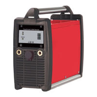
Fronius TransPocket 3500 Operating Instructions Manual (116 pages)
Brand:
Fronius
| Category:
Portable Generator
| Size: 4.63 MB
Table of Contents
Deutsch
3
Table of Contents
3
Allgemeines
5
Sicherheitsvorschriften
5
Erklärung Sicherheitshinweise
5
Verpflichtungen des Betreibers
6
Bestimmungsgemäße Verwendung
6
Umgebungsbedingungen
6
Verpflichtungen des Personals
7
Netzanschluss
7
Selbst- und Personenschutz
7
Angaben zu Geräuschemissions-Werten
7
Gefahr durch Schädliche Gase und Dämpfe
7
Gefahren durch Netz- und Arbeitsstrom
8
EMV Geräte-Klassifizierungen
9
EMV-Maßnahmen
9
EMF-Maßnahmen
10
Sicherheitsmaßnahmen am Aufstellort und Beim Transport
10
Sicherheitsmaßnahmen IM Normalbetrieb
10
Inbetriebnahme, Wartung und Instandsetzung
11
Sicherheitstechnische Überprüfung
11
Datensicherheit
12
Urheberrecht
12
Sicherheitskennzeichnung
12
Entsorgung
12
Allgemeine Informationen
13
Allgemeines
13
Lieferumfang
13
Prinzip
13
Gerätekonzept
13
Bestimmungsgemäße Verwendung
13
Warnhinweise am Gerät
14
Bedienelemente und Anschlüsse
15
Sicherheit
15
Netzanschluss
17
Generatorbetrieb
17
Vor der Inbetriebnahme
17
Aufstellbestimmungen
17
Sicherheit
17
Netzspannung Einstellen
19
Allgemein
19
Interface Rob Tst
20
Sicherheit
20
Lieferumfang
20
Gerätekonzept
20
Übersicht
21
Digitale Eingangssignale (Signale vom Roboter)
22
Kenngrößen
22
Schweißen ein
22
Sollwert Schweißstrom
23
Analoge Eingangssignale (Signale vom Roboter)
23
Allgemeines
23
Digitale Ausgangssignale (Signale zum Roboter)
24
Allgemeines
24
Stromquelle Bereit
24
Prozess Aktiv
24
Stromfluss
24
Analoge Ausgangssignale (Signale zum Roboter)
25
Allgemeines
25
Istwert Schweißspannung
25
Istwert Schweißstrom
25
Anschluss-Spezifikationen
26
Beschaltung der Ein- und Ausgänge
26
Anwendungsbeispiel
27
Gerätekonzept Profibus
28
Übersicht
28
Lieferumfang Interface Profibus
28
Sicherheit
28
Interface für Feldbus-Systeme
28
Ausgangssignale (von der Stromquelle zum Roboter)
29
Ein- und Ausgangssignale für Feldbus-Systeme
29
Eingangssignale (vom Roboter zur Stromquelle)
29
Signalbeschreibung Eingangssignale (vom Roboter zur Stromquelle)
31
Signalbeschreibung Ausgangssignale (von der Stromquelle zum Roboter)
31
Signalbeschreibungen Feldbus-Systeme
31
Sicherheit
34
Fehlerdiagnose
34
Allgemeines
34
Fehlerdiagnose, Fehlerbehebung
34
Status Anzeigen
35
Sicherheit
38
Allgemeines
38
Bei jeder Inbetriebnahme
38
Alle 2 Monate
38
Pflege, Wartung und Entsorgung
38
Alle 6 Monate
39
Entsorgung
39
Technische Daten
40
Interface ROB Tst
41
English
43
Explanation of Safety Notices
45
General
45
Safety Rules
45
Environmental Conditions
46
Obligations of Personnel
46
Obligations of the Operator
46
Proper Use
46
Danger from Toxic Gases and Vapours
47
Mains Connection
47
Noise Emission Values
47
Personal Protection and Protection of Others
47
Risks from Mains Current and Operating Current
48
EMC Device Classifications
49
EMC Measures
49
EMF Measures
49
Safety Measures at the Installation Location and During Transport
50
Safety Measures in Normal Operation
50
Commissioning, Maintenance and Repair
51
Disposal
51
Safety Inspection
51
Copyright
52
Data Protection
52
Safety Symbols
52
Device Concept
53
General
53
General Information
53
Principle
53
Proper Use
53
Scope of Supply
53
Warning Notices Affixed to the Device
54
Control Elements and Connections
55
Safety
55
Before Commissioning
57
Mains Connection
57
Safety
57
Setup Regulations
57
Generator-Powered Operation
58
Changing Mains Voltage
59
General
59
Setting the Mains Voltage
59
Device Concept
60
Rob Tst Interface
60
Safety
60
Scope of Supply
60
Overview
61
Digital Input Signals (Signals from Robot)
62
Parameters
62
Welding Start
62
Analogue Input Signals (Signals from Robot)
63
General
63
Welding Current Set Value
63
Current Flow
64
Digital Output Signals (Signals to Robot)
64
General
64
Power Source Ready
64
Process Active
64
Actual Welding Current Value
65
Actual Welding Voltage Value
65
Analogue Output Signals (Signals to Robot)
65
General
65
Connection Specifications
66
Input and Output Wiring Diagrams
66
Application Example
67
Device Concept Profibus
68
Interface for Field-Bus Systems
68
Overview
68
Safety
68
Scope of Supply Profibus Interface
68
Input and Output Signals for Field-Bus Systems
69
Input Signals (from Robot to Power Source)
69
Output Signals (from Power Source to Robot)
69
Description of Field-Bus System Signals
71
Description of Input Signals (from Robot to Power Source)
71
Description of Output Signals (from Power Source to Robot)
71
Fault Diagnosis
73
General
73
Safety
73
Troubleshooting
73
Status Indicators
74
At Every Start-Up
77
Care, Maintenance and Disposal
77
Every 2 Months
77
General
77
Safety
77
Disposal
78
Every 6 Months
78
Technical Data
79
TP 3500 CC Remote
79
ROB Tst Interface
80
Advertisement
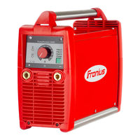
Fronius TransPocket 3500 Operating Instructions Manual (80 pages)
Brand:
Fronius
| Category:
Portable Generator
| Size: 4.93 MB
Table of Contents
Deutsch
5
Table of Contents
5
Sicherheitsvorschriften
7
Erklärung Sicherheitshinweise
7
Allgemeines
7
Bestimmungsgemäße Verwendung
8
Umgebungsbedingungen
8
Verpflichtungen des Betreibers
8
Verpflichtungen des Personals
9
Netzanschluss
9
Selbst- und Personenschutz
9
Angaben zu Geräuschemissions-Werten
9
Gefahr durch Schädliche Gase und Dämpfe
9
Gefahren durch Netz- und Arbeitsstrom
10
EMV Geräte-Klassifizierungen
11
EMV-Maßnahmen
11
EMF-Maßnahmen
12
Sicherheitsmaßnahmen am Aufstellort und Beim Transport
12
Sicherheitsmaßnahmen IM Normalbetrieb
12
Wartung und Instandsetzung
13
Sicherheitstechnische Überprüfung
13
Entsorgung
14
Sicherheitskennzeichnung
14
Datensicherheit
14
Urheberrecht
14
Allgemeine Informationen
15
Allgemeines
15
Lieferumfang
15
Prinzip
15
Gerätekonzept
15
Bestimmungsgemäße Verwendung
15
Warnhinweise am Gerät
16
Bedienelemente und Anschlüsse
17
Sicherheit
17
Vor der Inbetriebnahme
18
Sicherheit
18
Aufstellbestimmungen
18
Netzanschluss
18
Generatorbetrieb
18
Netzspannung Einstellen
19
Allgemein
19
Interface Rob Tst
20
Sicherheit
20
Lieferumfang
20
Gerätekonzept
20
Übersicht
21
Digitale Eingangssignale (Signale vom Roboter)
22
Kenngrößen
22
Schweißen ein
22
Analoge Eingangssignale (Signale vom Roboter)
23
Allgemeines
23
Sollwert Schweißstrom
23
Digitale Ausgangssignale (Signale zum Roboter)
24
Allgemeines
24
Stromquelle Bereit
24
Prozess Aktiv
24
Stromfluss
24
Analoge Ausgangssignale (Signale zum Roboter)
25
Allgemeines
25
Istwert Schweißspannung
25
Istwert Schweißstrom
25
Anschluss-Spezifikationen
26
Beschaltung der Ein- und Ausgänge
26
Anwendungsbeispiel
27
Interface für Feldbus-Systeme
28
Sicherheit
28
Lieferumfang Interface Profibus
28
Gerätekonzept Profibus
28
Übersicht
28
Ein- und Ausgangssignale für Feldbus-Systeme
29
Eingangssignale (vom Roboter zur Stromquelle)
29
Ausgangssignale (von der Stromquelle zum Roboter)
29
Signalbeschreibungen Feldbus-Systeme
31
Signalbeschreibung Eingangssignale (vom Roboter zur Stromquelle)
31
Signalbeschreibung Ausgangssignale (von der Stromquelle zum Roboter)
31
Fehlerdiagnose, Fehlerbehebung
33
Allgemeines
33
Sicherheit
33
Fehlerdiagnose
33
Status Anzeigen
34
Pflege, Wartung und Entsorgung
37
Sicherheit
37
Allgemeines
37
Bei jeder Inbetriebnahme
37
Alle 2 Monate
37
Alle 6 Monate
37
Entsorgung
37
Technische Daten
38
TP 3500 CC Remote
38
Interface ROB Tst
38
English
41
Safety Rules
43
Explanation of Safety Symbols
43
General
43
Proper Use
44
Environmental Conditions
44
Obligations of the Operator
44
Obligations of Personnel
45
Mains Connection
45
Protecting Yourself and Others
45
Noise Emission Values
45
Danger from Toxic Gases and Vapours
45
Risks from Mains Current and Operating Current
46
EMC Device Classifications
47
EMC Measures
47
EMF Measures
47
Safety Measures at the Installation Location and During Transport
48
Safety Measures in Normal Operation
48
Maintenance and Repair
49
Safety Inspection
49
Disposal
49
Safety Symbols
49
Data Protection
50
Copyright
50
General Information
51
General
51
Scope of Supply
51
Principle
51
Device Concept
51
Proper Use
51
Warning Notices Affixed to the Device
52
Control Elements and Connections
53
Safety
53
Before Commissioning
54
Safety
54
Setup Regulations
54
Mains Connection
54
Generator-Powered Operation
54
Setting the Mains Voltage
55
General
55
Changing Mains Voltage
55
Rob Tst Interface
56
Safety
56
Scope of Supply
56
Device Concept
56
Overview
57
Digital Input Signals (Signals from Robot)
58
Parameters
58
Welding Start
58
Analogue Input Signals (Signals from Robot)
59
General
59
Welding Current Set Value
59
Digital Output Signals (Signals to Robot)
60
General
60
Power Source Ready
60
Process Active
60
Current Flow
60
Analogue Output Signals (Signals to Robot)
61
General
61
Actual Welding Voltage Value
61
Actual Welding Current Value
61
Connection Specifications
62
Input and Output Wiring Diagrams
62
Application Example
63
Interface for Field-Bus Systems
64
Safety
64
Scope of Supply Profibus Interface
64
Device Concept Profibus
64
Overview
64
Input and Output Signals for Field-Bus Systems
65
Input Signals (from Robot to Power Source)
65
Output Signals (from Power Source to Robot)
65
Description of Field-Bus System Signals
67
Description of Input Signals (from Robot to Power Source)
67
Description of Output Signals (from Power Source to Robot)
67
Troubleshooting
69
General
69
Safety
69
Fault Diagnosis
69
Status Indicators
70
Care, Maintenance and Disposal
72
Safety
72
General
72
At Every Start-Up
72
Every 2 Months
72
Every 6 Months
72
Disposal
72
Technical Data
73
TP 3500 CC Remote
73
ROB Tst Interface
73
Appendix
75
Spare Parts List: Transpocket 3500 CC Remote
76
Circuit Diagram: Transpocket 3500 CC Remote
78
Fronius TransPocket 3500 Operating Instructions Manual (48 pages)
Brand:
Fronius
| Category:
Welding System
| Size: 1.83 MB
Table of Contents
Table of Contents
3
Safety Rules
5
Explanation of Safety Notices
5
General
5
Proper Use
6
Environmental Conditions
6
Obligations of the Operator
6
Obligations of Personnel
6
Mains Connection
7
Residual Current Protective Device
7
Protecting Yourself and Others
7
Noise Emission Values
8
Danger from Toxic Gases and Vapours
8
Danger from Flying Sparks
9
Risks from Mains Current and Welding Current
9
Meandering Welding Currents
10
EMC Device Classifications
10
EMC Measures
11
EMF Measures
11
Specific Hazards
11
Requirement for the Shielding Gas
12
Danger from Shielding Gas Cylinders
13
Safety Measures at the Installation Location and During Transport
13
Safety Measures in Normal Operation
14
Commissioning, Maintenance and Repair
14
Safety Inspection
15
Disposal
15
Safety Symbols
15
Data Protection
16
Copyright
16
General
17
Principle
17
Device Concept
17
Application Areas
17
Control Elements and Connections
18
Safety
18
Connections
18
Operating Elements
19
Before Commissioning
21
Safety
21
Proper Use
21
Setup Regulations
21
Mains Connection
21
Changing Mains Voltage (Only MVM Versions)
23
General Remarks
23
Mains Voltage Tolerance Range
23
Changing Mains Voltage
23
Single-Phase Operation
24
MMA Welding
25
Safety
25
Preparations
25
Selecting the Process
25
Adjusting Welding Current, Igniting the Arc
25
Hotstart Function (Used with Rutile and Cel Processes)
26
Softstart Function (Used with Basic Process)
26
Anti-Stick Function
26
TIG Welding
27
Safety
27
General
27
Preparations
27
Setting the Shielding Gas Flow Rate
28
Selecting the Process
28
Adjusting Welding Current, Igniting the Arc
28
TIG Comfort Stop Function
29
The Setup Menu
31
Setting Options
31
Functional Principle
31
Setting Parameters
31
Arc-Force Dynamic Parameter
32
Cel Characteristic Parameter
32
TIG Comfort Stop Parameter
32
Pulsing Frequency Parameter
33
Voltage Reduction Device (VRD Versions Only)
34
General
34
Safety Principle
34
Troubleshooting
35
Safety
35
Fault Diagnosis
35
Status Indicators
37
Care, Maintenance and Disposal
39
General
39
At Every Start-Up
39
Every 2 Months
39
Every 6 Months
39
Disposal
39
Average Consumption Values During Welding
40
Average Wire Electrode Consumption During MIG/MAG Welding
40
Average Shielding Gas Consumption During MIG/MAG Welding
40
Average Shielding Gas Consumption During TIG Welding
40
Technical Data
41
Safety
41
Generator-Powered Operation
41
Transpocket 2500, 2500 RC, 2500 TIG
41
Transpocket 2500 MVM, 2500 TIG MVM
42
Transpocket 3500, 3500 RC, 3500 TIG
43
Transpocket 3500 MVM, 3500 TIG MVM
44
Overview with Critical Raw Materials, Year of Production of the Device
45
Advertisement
Fronius TransPocket 3500 Operating Instructions Manual (48 pages)
Rod electrode power source
Brand:
Fronius
| Category:
Portable Generator
| Size: 0.97 MB
Table of Contents
Table of Contents
3
Safety Rules
5
Explanation of Safety Notices
5
General
5
Proper Use
5
Environmental Conditions
6
Obligations of the Operator
6
Obligations of Personnel
6
Mains Connection
6
Residual Current Protective Device
7
Protecting Yourself and Others
7
Noise Emission Values
7
Danger from Toxic Gases and Vapours
8
Danger from Flying Sparks
8
Risks from Mains Current and Welding Current
9
Meandering Welding Currents
10
EMC Device Classifications
10
EMC Measures
10
EMF Measures
11
Specific Hazards
11
Requirement for the Shielding Gas
12
Danger from Shielding Gas Cylinders
12
Safety Measures at the Installation Location and During Transport
13
Safety Measures in Normal Operation
13
Commissioning, Maintenance and Repair
14
Safety Inspection
14
Disposal
14
Safety Symbols
15
Data Protection
15
Copyright
15
General
16
Principle
16
Device Concept
16
Application Areas
16
Control Elements and Connections
17
Safety
17
Connections
17
Operating Elements
18
Before Commissioning
20
Safety
20
Proper Use
20
Setup Regulations
20
Mains Connection
20
Changing Mains Voltage (Only MVM Versions)
22
General Remarks
22
Mains Voltage Tolerance Range
22
Changing Mains Voltage
22
Single-Phase Operation
23
MMA Welding
24
Safety
24
Preparations
24
Selecting the Process
24
Adjusting Welding Current, Igniting the Arc
24
Hotstart Function (Used with Rutile and Cel Processes)
25
Softstart Function (Used with Basic Process)
25
Anti-Stick Function
25
TIG Welding
26
Safety
26
General
26
Preparations
26
Setting the Shielding Gas Flow Rate
27
Selecting the Process
27
Adjusting Welding Current, Igniting the Arc
27
TIG Comfort Stop Function
28
The Setup Menu
30
Setting Options
30
Functional Principle
30
Setting Parameters
30
Arc-Force Dynamic Parameter
31
Cel Characteristic Parameter
31
TIG Comfort Stop Parameter
31
Pulsing Frequency Parameter
32
Voltage Reduction Device (VRD Versions Only)
33
General
33
Safety Principle
33
Troubleshooting
34
Safety
34
Fault Diagnosis
34
Status Indicators
36
Care, Maintenance and Disposal
38
General
38
At Every Start-Up
38
Every 2 Months
38
Every 6 Months
38
Disposal
38
Average Consumption Values During Welding
39
Average Wire Electrode Consumption During MIG/MAG Welding
39
Average Shielding Gas Consumption During MIG/MAG Welding
39
Average Shielding Gas Consumption During TIG Welding
39
Technical Data
40
Safety
40
Generator-Powered Operation
40
Transpocket 2500, 2500 RC, 2500 TIG
40
Transpocket 2500 MVM, 2500 TIG MVM
41
Transpocket 3500, 3500 RC, 3500 TIG
42
Transpocket 3500 MVM, 3500 TIG MVM
43
Overview with Critical Raw Materials, Year of Production of the Device
44
Fronius TransPocket 3500 Operating Instructions Manual (32 pages)
Rod electrode power source
Brand:
Fronius
| Category:
Portable Generator
| Size: 1.97 MB
Table of Contents
Table of Contents
3
General
5
Principle
5
Device Concept
5
Application Areas
5
Control Elements and Connections
6
Safety
6
Connections
6
Operating Elements
7
Before Commissioning
8
Safety
8
Proper Use
8
Setup Regulations
8
Mains Connection
8
Changing Mains Voltage (Only MVM Versions)
9
General Remarks
9
Mains Voltage Tolerance Range
9
Changing Mains Voltage
9
Single-Phase Operation
10
MMA Welding
11
Safety
11
Preparations
11
Selecting the Process
11
Adjusting Welding Current, Igniting the Arc
11
Hotstart Function (Used with Rutile and Cel Processes)
12
Softstart Function (Used with Basic Process)
12
Anti-Stick Function
12
TIG Welding
13
Safety
13
General
13
Preparations
13
Setting the Shielding Gas Flow Rate
13
Selecting the Process
14
Adjusting Welding Current, Igniting the Arc
14
TIG Comfort Stop Function
15
The Setup Menu
17
Setting Options
17
Functional Principle
17
Setting Parameters
17
Arc-Force Dynamic Parameter
18
Cel Characteristic Parameter
18
TIG Comfort Stop Parameter
18
Pulsing Frequency Parameter
19
Voltage Reduction Device (VRD Versions Only)
20
General
20
Safety Principle
20
Troubleshooting
21
Safety
21
Fault Diagnosis
21
Status Indicators
23
Care, Maintenance and Disposal
25
General
25
At Every Start-Up
25
Every 2 Months
25
Every 6 Months
25
Disposal
25
Technical Data
26
Safety
26
Generator-Powered Operation
26
Transpocket 2500, 2500 RC, 2500 TIG
26
Transpocket 2500 MVM, 2500 TIG MVM
27
Transpocket 3500, 3500 RC, 3500 TIG
27
Transpocket 3500 MVM, 3500 TIG MVM
28
Advertisement
Related Products
Fronius TransTig 2200 Comfort
Fronius TransTig 2500 Comfort
Fronius TransTig 4000 Comfort
Fronius TransArc 150 Leybold
Fronius TransTig 2600
Fronius TransTig 2600 Cel
Fronius TransTig 5000 Comfort
Fronius TP 2500 RC
Fronius TP 2500 VRD
Fronius TP 4000 CEL
Fronius Categories
Welding System
Inverter
Welding Accessories
Battery Charger
Measuring Instruments
More Fronius Manuals
Login
Sign In
OR
Sign in with Facebook
Sign in with Google
Upload manual
Upload from disk
Upload from URL