
Related Manuals for GE SBC330 3U VPX


Summary of Contents for GE SBC330 3U VPX
- Page 1 Intelligent Platforms Hardware Reference Manual SBC330 3U VPX Single Board Computer Edition 3 Publication No. SBC330-0HH/3...
- Page 2 Amendments to block diagram. February 2010 Board Rev5 May 2011 Errata to Sections 4.3.2 and 8.1, Figure 5-2, and Table 5-5. Waste Electrical and Electronic Equipment (WEEE) Returns GE Intelligent Platforms Limited is registered with an approved Producer Compliance Scheme (PCS) and, subject to suitable contractual arrangements being in place, will ensure WEEE is processed in accordance with the requirements of the WEEE Directive. GE Intelligent Platforms Limited. will evaluate requests to take back products purchased by our customers before August 13, 2005 on a case by case basis. A WEEE management fee may apply. 2 SBC330 3U VPX Single Board Computer Publication No. SBC330-0HH/3...
-
Page 3: Table Of Contents
Contents 1 • Introduction ..............8 1.1 Features. - Page 4 5.10.3 Machine Check Exception ..............42 4 SBC330 3U VPX Single Board Computer...
- Page 5 5.10.4 Soft reset ................43 5.10.5 System Management Interrupt .
- Page 6 A.2.2 Current consumption ..............86 6 SBC330 3U VPX Single Board Computer...
- Page 7 A.2.3 Power requirements ...............87 A.2.4 GPIO electrical characteristics .
-
Page 8: Introduction
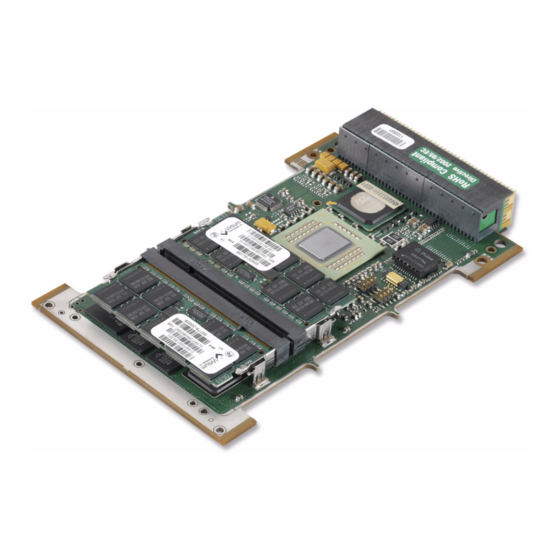
1 • Introduction The SBC330 is a 3U VPX Single Board Computer, and is part of GE Intelligent Platforms’ VPXtreme3 range of products. It uses the Freescale MPC8641D dual‐ core Integrated Host Processor, which contains two e600 PowerPC processing cores running at 1.0 to 1.5 GHz with dual DDR2 memory controllers, serial fabric and I/O interfaces. The SBC330 offers up to 2 GBytes of DDR2 SDRAM with ECC, up to 256 MBytes of Flash memory, two Gigabit Ethernet channels, on‐board serial communications (RS232), four USB2 ports, two SATA‐2.0 ports and two independent PCI Express links routed to the VPX backplane: a direct 8‐lane port for extreme graphics applications, and a 4‐lane port routed via an on‐board PCIe switch. The MPC8641D is connected to all on‐board PCI devices using PCI Express. This is a high‐speed serial interconnect running at 2.5 Gbits/second, providing a total bandwidth of 1 GBytes/second to and from the processor, through a non‐blocking switch architecture. PCI Express is software compatible with PCI and bridges are used where connection to PCI or PCI‐X components is required. Figure 1-1 8 SBC330 3U VPX Single Board Computer Publication No. SBC330-0HH/3... -
Page 9: Features
1.1 Features • Dual core MPC8641D processor • Four USB II ports, up to 480 at up to 1.5 GHz, each core with 1 Mbits/second MByte cache • Two SATA‐2 ports (300 Gbits/ • Expandable 2 x ECC DDR2 second) SODIMMS each offering 2 GByte • Two RS232 serial ports, each with @ 533 MHz hardware flow control • 256 MByte password or • Eight GPIO lines with individual hardware protected 32‐bit wide direction assignment Flash • VPX slot 1 Master capabilities • Off‐board direct PCIE‐8 lane and • PS2 Keyboard and Mouse (switched) PCIE‐4 lane: Root interfaces Complex or Slave • I C devices – 8 KByte EEPROM, Real Time Clock, Elapsed Time Indicator, Temperature Sensor 1.2 Associated Documents The following documents provide additional information relevant to the SBC330: LINK... -
Page 10: Web Sites
This manual uses the following types of notice: Notes call attention to important features or instructions, and are shown as follows: NOTE Note text in here. Cautions call attention to actions that may cause system damage or loss of data, and are shown as follows: CAUTION Caution text here. Warnings call attention to actions that may cause risk of personal injury, and are shown as follows: WARNING Warning text here. Recommendations give guidance on procedures that may be tackled in a number of ways, and are shown as follows: Tip text here. Further information can be found by following hyperlink, as shown here: LINK Link text here. 10 SBC330 3U VPX Single Board Computer Publication No. SBC330-0HH/3... -
Page 11: Safety Notices
and respectively. NOTE When describing transfer rates, ‘k’ ‘M’ and ‘G’ mean x10 , x10 and x10 not x2 , x2 and x2 Signal names ending with a tilde (~) denote active low signals; all other signals are active high. GE Intelligent Platforms Ltd is referred to in the text as GEIP. 1.5 Safety Notices 1.5.1 Safety summary Observe the following general safety precautions during operation of this equipment. Failure to comply with these precautions or with specific Warnings and/or Cautions elsewhere in this manual violates safety standards of design, manufacture and intended use of the equipment. GE Intelligent Platforms Ltd assumes no liability for the user’s failure to comply with these requirements. The safety precautions listed below represent warnings of certain dangers of which GEIP is aware. Take note of these warnings and take all other safety precautions necessary for the safe operation of the equipment in your operating ... -
Page 12: Flammability
Only handle the board at the edges, heatsink, or front panel. 1.7 Heatsink CAUTION Do not remove the heatsink. The heatsink is thermally bonded to the ICs and will generally not separate from the board by removal of the screws alone. There are no user‐alterable components underneath the heatsink, so users should have no reason to remove it. With the SBC330, the SODIMM cover may be removed and reattached by a user. In rare instances a user may be specifically instructed to remove a heatsink cover by GE staff. However, this does not mean that users should attempt reattachment of the heatsink, as this requires precise torque on the securing screws. Over‐ tightening the screws may cause the heatsink to damage components beneath it. Removal and re‐attachment of the heatsink should only be carried out by the factory. 12 SBC330 3U VPX Single Board Computer Publication No. SBC330-0HH/3... -
Page 13: Technical Support
1.8 Technical Support For technical assistance please register support requests using the Technical Support Request Form available through the GE Intelligent Platforms (GEIP) web site at: LINK http://defense.ge-ip.com/support/embeddedsupport/locator Your query will be logged on the Technical Support database and allocated a unique Service Request (SR) number for use in future correspondence. Alternatively, you may also contact GEIPʹs Technical Support via: LINK support .towcester.ip@ge.com TELEPHONE +44 (0) 1327 322760 1.9 Returns If you need to return a product, there is a Return Materials Authorization (RMA) request form that can be printed out and filled in, available via the web site Repairs page. LINK http://defense.ge-ip.com/support/embeddedsupport/rmalocator Follow the “Download RMA Request Form (Word Doc)” hyperlink under “DSP, SBCs, Multiprocessors and Graphics (Formerly Radstone)”. Please do not return products without first contacting the GEIP Repairs facility. Publication No. SBC330-0HH/3 Introduction 13... -
Page 14: Identification And Inspection
2.1 Product Identification The SBC330 is identified by labels at strategic positions. These can be cross‐ checked against the Advice Note provided with your delivery. Identification labels, similar to this, attached to the shipping box and the antistatic bag provide identical information: SBC330 product code, product description, equipment number and board revision. On the board within the antistatic bag, there is an identifying label similar to this attached to the PCB. On conduction‐cooled versions of the board (build levels 4 and 5), there is also a label similar to this attached to the front panel. See Section A.6 for more details on the product code. 2.2 Inspection When handling the SBC330, observe antistatic precautions. Visually examine the SBC330 for any physical damage. If the SBC330 is not received in perfect physical condition, report this to the Customer Services department immediately. 14 SBC330 3U VPX Single Board Computer Publication No. SBC330-0HH/3... -
Page 15: Installation And Power-Up
3 • Installation and Power-Up 3.1 Installation SBC330 boards should only be installed into 3U VPX backplanes. With the VPX connector standard, great care should be exercised in installation and removal of all daughter boards into the backplanes. The insertion forces are significant. CAUTION The SBC330 has been specifically designed for use with 3U VPX backplanes and is not compatible with 6U backplanes. Plugging the SBC330 into a 6U backplane may cause permanent component damage. -
Page 16: Cooling
You can now power‐up the unit. As the SBC330 runs through its boot sequence, the monitor (COM1, COM2) should display the initialization progress. 3.4 Connecting to SBC330 To interact with the SBC330, the minimum requirement is a control terminal such as PC‐based Windows ‘HyperTerminal’ connection present on the serial COM1 port. An Ethernet connection is required for Host/Target interaction until the kernel/application software is stored in Flash. At GEIP, TeraTerm is used as it allows long scroll buffers, which is useful in debug. For development systems, connection to the Serial and Ethernet I/O can be achieved using the SBC330RTM‐11 Rear Transition Module. This converts the pinout of the SBC330 in the VPX backplane connectors to industry‐standard I/O connectors. 16 SBC330 3U VPX Single Board Computer Publication No. SBC330-0HH/3... -
Page 17: Power Up Sequence
The SBC330RTM has two options for serial I/O: a single mini‐DB9 connector that hosts both COM1 and COM2 is provided, or via a 2x10‐way header suitable for use with GEIP’s SIOX600 ribbon to DB9 serial adapter. COM1 is configured as DTE with default settings of 9600 baud, 8 bits/character, 1 stop bit, parity disabled and no flow control. For the Ethernet ports, a CAT5 (or better) straight‐through patch cable for 10/100/ 1000BaseTX. VPX I/O Modules Manual, publication number VPXIOM-0HH, contains more details on fitting RTMs. Similar antistatic and safety precautions apply when handling and/or installing I/O modules as for the SBC330. 3.5 Power Up Sequence 3.5.1 On-board sequencing Several components on the SBC330 receive multiple power supplies and require ... - Page 18 The full SBC330 power‐on‐reset sequence takes approximately 100mS: • Drive PSU_SEQ_OUT low • Wait for VS3 to reach 4.49Volts. (90 percentile triggering) • Wait for PSU_SEQ_IN signal to be high, or for 500ms • Release PSU_SEQ_OUT • Following the PSU_SEQ_OUT signal, which occurs once all the on‐board PSUs have active POWER_GOOD signals, if the board is the slot‐1 VPX controller then the backplane SYS_RESET signal is driven low for a further 20 mS. 18 SBC330 3U VPX Single Board Computer Publication No. SBC330-0HH/3...
-
Page 19: Configuration
4 • Configuration This section describes the configuration of jumpers on the SBC330. The board is delivered with push‐on links, but for more rugged or military applications, jumper pins must be connected using wire wraps and conformal‐coat. 4.1 Jumper Locations The SBC330 has two banks of 4 x 2‐way jumpers that affect booting and need to be set correctly. 4.2 Default Link Settings The SBC330 is shipped from the factory with some links fitted. This simplifies the most likely use of the SBC330. Some jumpers are essential and some are not. Before changing any of the link options, refer to the following sections. NOTE If you are about to install your board and power-up for the first time, leaving your board in the default configuration will enable board operation to be proven prior to tackling any further configuration issues. -
Page 20: P10 Header
4.3.2 Flash password/Boot Sector protection Without pins 3 and 4 being linked, no write access is allowed to the boot sector, which prevents any erroneous user software remapping of User Flash areas, overwriting boot sector Flash information. The address region protected is the top Errata 8 MByte region of the local bus (0xFF80 0000 to 0xFFFF FFFF), which comprises all May 2011 four of the separate 2 MByte core 0 boot sites. 4.3.3 Boot Flash image selection The Boot Flash for processing core 0 is divided into four 2 MByte sections named Main, Alternate, Extended, and BANC (Boot Area Non Corruptible). These allow for three different boot images to be loaded from the Flash, plus (when available) a factory‐programmed boot image that allows the user to recover if a non‐ bootable image is erroneously put into Flash. The different boot images allow the board to boot different code from power up. For instance, it enables GEIP to program both Functional Test Code (FTS) and VxWorks Operating Systems concurrently into the same board to aid diagnostics. Another example may be to allow booting as a PCIe root complex or a PCIe end‐point on either of the two PCIE‐Express ports, which may be useful in multi‐board applications. Pins 5‐6 and 7‐8 form a binary combination that alters the order of the 2 MByte (0x2000) boot regions in the Flash memory and selects which image is used at boot time. The state of these jumper links is reflected in the Flash Control Register. 20 SBC330 3U VPX Single Board Computer Publication No. SBC330-0HH/3... -
Page 21: P12 Header
Table 4-2 Flash Jumper operation Link Configuration Pins 5 and 6 Not fitted Fitted Not fitted Fitted Pins 7 and 8 Not fitted Not fitted Fitted Fitted Binary (7-8)(5-6) Address Memory Configuration FFFF FFFF Main Alternative Extended BANC FFE0 0000 FFD0 FFFF Alternative Main... -
Page 22: Jtag
Table 4-5 P12 AMP/SMP Mode Pin 1 to Pin 2 Setting Function Not linked SMP Mode. No core 1 addressing offset Linked AMP Mode. Core 1 has 256 MByte memory offset 22 SBC330 3U VPX Single Board Computer Publication No. SBC330-0HH/3... -
Page 23: Functional Description
5 • Functional Description 5.1 Features • Freescale MPC8641 Dual Core Integrated Host Processor at 1.0, 1.33, or 1.5 GHz • One x8 lane PCI Express link direct off‐board • One x4 lane PCI Express link via 4 port switch • Expandable 2 GBytes dual‐channel DDR2 memory with ECC • Up to 512 MByte of Flash memory with enhanced write‐protection features • PCI Express board interconnect with non‐blocking switch architecture • Two 10/100/1000BaseT Ethernet ports • Two Serial I/O channels (RS232), both with hardware flow control • Four USB 2.0 ports (480 Mbits/second) • Two Serial ATA disk interfaces (up to 3.0 Gbits/second) • Up to 8 bits of General Purpose digital I/O with interrupt capability • Real Time Clock • Elapsed Time Indicator • Watchdog timers • CPU die and ambient temperature sensors • VPX slot 1 capabilities •... -
Page 24: Block Diagram
Figure 5-1 SBC330 Block Diagram 5.2 Integrated Host Processor The SBC330 is based around the Freescale MPC8641D Integrated Host Processor. This provides: • Dual e600 PowerPC processing • Local Bus Interface cores • I C Interfaces • Internal MPX bus • Serial I/O Interfaces • Dual DDR2 Memory Controllers • DMA Engines • PCI Express Interface • Interrupt Controller • Gigabit Ethernet Interfaces 24 SBC330 3U VPX Single Board Computer Publication No. SBC330-0HH/3... -
Page 25: Powerpc Processing Cores
• AltiVec Vector Unit • Enhanced branch prediction capabilities • MMU and integral FPU • The e600 processing core implements a fully static architecture and offers sophisticated power management capabilities. The SBC330 is offered in three speeds. However, users can configure the speed of the SBC330 in software and request firmware that supports intermediate speeds. The SBC330 feeds a 66.6 MHz clock into the 8641D processor, and registers in the FPGA allow a user to select the multipliers that are available within the 8641D to achieve different speeds. Current firmware supports up to MPX Bus (Platform)/Core speed options. Contact your nearest GE Intelligent Platforms Sales Office or Agent for more information. Table 5-1 Processor Core Frequency Options Core Frequency (MHz) MPX Bus Frequency (MHz) 1000 1333 1500 User User 5.2.2 Dual Processing Core operation The MPC8641D contains two processing cores. Following reset, processing core 1 ... -
Page 26: Mpx (Platform) Bus
FC00 0000 FBFF FFFF FBFF FFFF AXIS F800 0000 F800 0000 F7FF FFFF F7FF FFFF Reserved F000 0000 F000 0000 EFFF FFFF EFFF FFFF User Flash E000 0000 E000 0000 26 SBC330 3U VPX Single Board Computer Publication No. SBC330-0HH/3... -
Page 27: System Ram
Table 5-2 VxWorks Default Memory Map Internal 32-bit Core 0 Internal 32- bit Core 1 DFFF FFFF DFFF FFFF PCIe 2 memory C000 0000 C000 0000 BFFF FFFF BFFF FFFF PCIe 1 memory 8000 0000 8000 0000 7FFF FFFF 7FFF FFFF 2000 0000 2000 0000 1FFF FFFF... -
Page 28: Boot Flash
Boot’ bit set 0xFFFF FFFF Core 0 BANC Core 0 BANC 0xFFFC 0000 Spare Spare 0xFFE0 0000 Core 0/1 Extended Core 0 Extended 0xFFC0 0000 Core 0/1 Alternate Core 0 Alternate 0xFFA0 0000 Core 0/1 Main Core 0 Main 0xFF80 0000 Spare 0xFF60 0000 Core 1 Extended 0xFF40 0000 Core 1 Alternate User 0xFF20 0000 Flash Core 1 Main 0xFF00 0000 User Flash Not to scale 28 SBC330 3U VPX Single Board Computer Publication No. SBC330-0HH/3... -
Page 29: User Flash
By default, shipped boards have the top 8 MBytes reserved as boot Flash, and the Core 1 Boot bit in the Flash Control Register (offset 0x0044, see the Registers section) is set to 0. If core 1 is required to boot from a different image, then the core 0 boot loader must include code to set the Core 1 Boot bit to ʹ1ʹ before releasing core 1. See the SBC330 software manual for further description of BootROM loaders. The BANC (Boot Area Non Corruptible) recovery boot image area contains a 256 KByte factory‐programmed boot image, shared by both processing cores, allowing the Flash to be reprogrammed if other boot images become corrupted. This area is protected by hardware and is not writeable by the user. The remainder of this 2 MByte boot image can be used to store BIT results. The boot Flash is accessed using Chip Select 0 on the Local Bus Controller of the MPC8641D, and is configured as the default boot location for the PowerPC reset vector (0xFFF0 0100). The boot areas are mapped into a 16 MByte window. The active boot image for Core 0 is set using P10 pins 5 to 8 as described in Chapter 4 • . The Core 1 boot region is either the same as the Core 0 boot region or is the same offset by 8 MBytes if the Core 1 Alternative Boot bit is set in the Flash register. The Core 0 and Core 1 boot regions are linked because there are insufficient jumpers on SBC330 to make them completely independent. 5.3.5 User Flash Any Flash that is not used as Boot Flash is designated as User Flash and is intended to hold user application code or data. User Flash is accessed using Chip Select CS1 on the Local Bus Controller of the MPC8641D. Chip Select 1 is intended for use by Processing Core 0 and may be used to access all areas of Flash, as required when using a single‐core or SMP system. The 8 MBytes of Boot Flash appears at the top of the User Flash area, with the four boot images appearing in their physical locations (i.e. 0xEF80 0000 to 0xEFFF FFFF mirrors 0xFF80 0000 to 0xFFFF FFFF). Chip Select 1 accesses are unaffected by the boot‐swap jumper links. Programming at a given offset therefore always stores at that given offset. For example, using CS0, programming at 0xFFF0 0000 may actually program into Flash at 0xFFFD 0000 if P10 pins 5 and 6 are linked. Using CS1, programming 0xEFF0 0000, programs into Flash at 0xEFF0 0000 (which is also equivalent to 0xFFF0 0000), regardless of the Flash boot link settings. -
Page 30: Flash Sector Protection
Sectors that are locked using the Persistent mode may not be unlocked using this mechanism. NOTE Do not rely on non-persistent protection, as it may be subsequently altered by software. If further protection is required, use the Persistent protection method. For further details of the protection mechanisms, refer to the Spansion S29GL01Pxxx data sheets. 30 SBC330 3U VPX Single Board Computer Publication No. SBC330-0HH/3... -
Page 31: Pci Express Infrastructure
5.4 PCI Express Infrastructure All PCI devices and mezzanine sites on the SBC330 are connected to the MPC8641D using PCI‐Express (PCIe). The block diagram (Figure 5‐1) shows the PCIe/PCI structure. PCIe is a high‐speed serial, point‐to‐point interconnect running at 2.5 Gbits/ second in each direction. PCIe links are scalable, meaning that multiple lanes can be used between devices to increase the aggregate bandwidth. A comparison of the bandwidth of PCIe links with PCI implementations are shown in the table below. Table 5-6 PCI Bus Bandwidth Bus Type Bus Width Frequency Notes (MBytes/sec) 32-bit 33 MHz 32-bit 66 MHz 64-bit 66 MHz PCI-X 64-bit 133 MHz 1066 PCIe 2.5 Gbps Per Direction PCIe 2.5 Gbps... -
Page 32: Mpc8641D
0 to 7 MPC8641D SerDes Port Upstream 1: 8-lane link 8 to 11 VPX connector external Transparent 4-lane link 12 only SIL3132 SATA bridge Transparent 14 & 15 PEX8114 PCI-X bridge Transparent 32 SBC330 3U VPX Single Board Computer Publication No. SBC330-0HH/3... - Page 33 A serial SPI‐type EEPROM (ATMEL 25256A (32Kx 8)) is used to configure registers within the device at power‐up. This EEPROM is write‐protected by default and can be write‐enabled by clearing the Serial EEPROM Write Protect bit in the Miscellaneous Functions Register (offset 0x28). This bit may only be cleared when the NVMRO signal on the VPX backplane is negated. In the event of this EEPROM device becoming corrupted, it is possible to recover it by toggling the EEPROM Presence Detect bit of the Miscellaneous Functions register. In this case, the switch configuration is defined by hardware strapping. Each port can negotiate down to smaller link widths if required (such as if a fault occurs on any particular lane). Port widths of x1, x2, x4 and x8 are supported. Port 0 is connected to the MPC8461D and is usually configured as the Upstream Port. The PEX8518 is connected to on‐board I C Bus 1 (address 0xB0) to allow configuration by the processor and out‐of‐band monitoring of link status. The status of all of the on‐board links, and the two VPX links can be determined from LEDs on the rear of the board (see Chapter 7 • ) Further status information (the number of active lanes, etc.) can be ascertained from registers within the Switch device. The default Switch setting is for the external 4‐lane port to be Transparent. This allows the SBC330 to attach to PCIe End‐Point devices. To connect together two intelligent devices on PCIE, such as two SBC330 processor boards, on one of the boards the PEX8518 Switch needs to be set as Non‐Transparent for the external port (Port 1). To achieve this, the SPI EEPROM must be reprogrammed via Software. This changes the power‐up configuration of the switch to create a non transparency such that there is no collision on memory domains. The intelligent device that has not been set to have a non‐transparent port passes configuration through to the PEX8518 Switch port 1, but not beyond it. The local processor on the board that has been set such that the PEX8518 port 1 is non‐transparent will not try to pass any configuration cycles to the remote host device. In this way, full PCI configuration is achieved. On the SBC330 there is an orange LED (DS218) connected to the PEX8518 Switch to show if the external PCIe 4‐lane port is connected. If the LED is lit, then PCIe link connection has been established. This LED will not light between two SBC330 boards if either both boards or neither board have had their default PEX8518 SPI EEPROM contents adjusted so that 1 of the boards sets Port 1 to be Non‐ transparent. Figure 5-3 Non-Transparent Port Setting for Host- Host PCIe Communication Publication No.
-
Page 34: Pci Express To Pci Bridge
Device Width Window Size Chip Select Boot Flash 32-bit 8/16 MBytes User Flash 32-bit Up to 512 MBytes FPGA functions 32-bit (many registers 16-bit) 32 KBytes 3 to 7 Not used 34 SBC330 3U VPX Single Board Computer Publication No. SBC330-0HH/3... -
Page 35: Local Bus Control Fpga
The FPGA is used to form several registers that are visible to the processor on the local bus and are accessed using the CS2 chip select line of the M8641D. In the default VxWorks release, the registers are located at address 0xFC00 0000, but the location of these registers in memory space is defined solely on the CS2 BAR and so they are movable. 5.6 Local Bus Control FPGA The Local Bus Control FPGA is a Lattice MachXO device that provides the following functions: • Local bus address latching and chip select generation for Flash/NVRAM • Control/Status registers • Watchdogs • GPIO controller • Secondary interrupt controller 5.6.1 Ethernet The MPC8641D has four on‐chip enhanced 3‐speed Ethernet Controllers (called eTSECs). These incorporate a media access controller (MAC) that supports 10/100/ 1000BaseT, and half‐ and full‐duplex operation. The eTSECs support several TCP offload features (including checksum generation and verification) that reduce the amount of software interaction required. Jumbo frames are also supported. The SBC330 uses two of these controllers to provide external 1000/100/10 Ethernet interfaces. eTSEC1 and eTSEC3 are used, as these have independent connections to the platform bus. The controllers are connected via a GMII interface to Marvell 88E1111 PHYs. The PHYs are isolated from the backplane using transformer‐ coupled magnetics. The PHYs are configured at power‐up to have MDI addresses of 0x1 and 0x3, corresponding to the eTSEC port to which they are connected. The network (MAC) addresses are factory configured. Two LEDs indicating link‐receive are provided on the rear side at the front edge of the SBC330 board to allow easy monitoring of Ethernet interface. These LEDs should flash (yellow) when the Ethernet is receiving traffic. 5.6.2 Serial ports The DUART module in the MPC8641D provides COM1 and COM2, which ... -
Page 36: Usb
5.6.3 USB An NEC μPD720101 device provides four USB ports on the SBC330 and is connected to the PCI bus. The device is capable of operation at USB standard low‐ , full‐ or high‐ speed. The device contains two OHCI controllers (for USB1.1 operation) and one EHCI controller (for USB2.0 operation). Alternate ports use a different OCHI controller for USB1.1 operation and ports arbitrate to share the EHCI controller for USB2.0 operation. The internal functions are configured as follows: Table 5-10 USB Device Functions Controller PCI Function No Interrupt OHCI 0 INTA~ OHCI 1 INTB~ EHCI INTC~ An in‐line common‐mode choke is fitted to the USB I/O pairs to filter high frequency noise. This improves signal integrity and helps to reduce EMI emissions. The USB ports are available on the P1 and P2 connectors. 36 SBC330 3U VPX Single Board Computer Publication No. SBC330-0HH/3... -
Page 37: Serial Ata
5.6.4 Serial ATA A Silicon Image Sil3132 device provides two Serial ATA (SATA) ports from the SBC330, supporting Generation 2 transfer speeds of at 3.0 Gbits/second. The device is connected to the PEX8518 switch via a x1 PCIe link. The SATA device has a dedicated I C EEPROM (not visible from the processor I C interfaces), which can be used to configure registers within the device if required. The EEPROM is write‐protected by default and can be write‐enabled by clearing the I C EEPROM Write Protect bit in the Miscellaneous Functions Register. There are 2 yellow activity LEDs on the rear of the SBC330 to indicate activity on channels 0 and 1. 5.6.5 General Purpose I/O The SBC330 supports eight General Purpose digital I/O (GPIO) lines. These are 3.3V single‐ended signals with 5V tolerance. These signals are controlled by the Local Bus FPGA and can be configured as inputs, with the ability to generate level‐ or edge‐triggered interrupts, or totem pole outputs that switch to CMOS levels. The lines are protected via an in‐line IDT QuickSwitch FET device that limits any over‐voltages seen by the FPGA. The in‐line FET modifies the switching characteristic of the lines, from that of the FPGA bi‐directional transceiver, but testing has shown that switching at up to the local bus speed of 50 MHz is possible. Each GPIO bit input is protected by quick switch devices, which limit the input voltage seen by the Local Bus Control FPGA to a safe level. Electrical characteristics of the GPIO pins can be found in Section A.2.4 GPIO lines 0 and 1 (on VPX connector P2 A15 and B15 respectively) are dual function and are reserved for the use of GEIP’s AXIS Multiprocessor Message Passing software when used. All GPIO registers are in the Local Bus FPGA, and are defined in Chapter 6 • Publication No. SBC330-0HH/3 Functional Description 37... -
Page 38: I2C
Bus 0 Bus 1 Device Address (Hex) Device Address (Hex) Read Write Read Write EEPROM PEX8518 SPD 1 PCIe Clock SPD 2 Temp Sensor PWR MAN DS1682 ETI MC8641D MC8641D 38 SBC330 3U VPX Single Board Computer Publication No. SBC330-0HH/3... -
Page 39: Real Time Clock
5.7.2 Real Time Clock The SBC330 provides an Epson RX8581_NB Real Time Clock (RTC) device with a minimum of 1 second resolution. The RTC can be powered from the VPX backplane P3V3_AUX or the VBAT signal when the main power supply is removed. The interrupt output of the RTC can generate an interrupt to either processor core, via the Local Bus FPGA. The ‘programmable square wave’ output from this device is also connected to the FPGA. However, current firmware does not make any use of the signal. 5.7.3 Elapsed Time Indicator A Dallas DS1682 Elapsed Time Indicator (ETI) is provided to log the amount of time the board is powered and the number of power cycles. 5.7.4 Temperature sensors The SBC330 has two ADT7461 temperature sensors. One remotely monitors the core temperature of the MPC8641D and the other monitors the ambient temperature at its location on the PCB. The device is located directly underneath the processor, next to the core PSU, which has been thermally modeled to be a hot spot on the PCB. The temperature sensors can generate interrupts to either processor core, via the Local Bus FPGA, at two software‐defined thresholds. Using the Secondary interrupt controller in the Local Bus Control FPGA, these thresholds can optionally be configured to generate an interrupt and further can be used to switch off the power supplies to the board. The current release of firmware has this feature implemented but disabled. Future releases will allow users to enable or disable the feature. 5.7.5 Power Supply manager The SBC330 uses a Lattice ispPAC‐POWR1014A to monitor and sequence the on‐ board voltages. The device provides an I C interface that can be used to access an internal A‐to‐D converter to measure the value of each of the on‐board voltage rails. Discrete inputs to and outputs from the device can also be monitored. -
Page 40: I2C Reset
0xC6 01101 0xD4 11010 0xB8 10011 0xC8 01100 0xD6 11001 0xBA 10010 0xCA 01011 0xD8 11000 0xBC 10001 0xCC 01010 0xDA The local processor communicates with the BMM via the COM2 port from the MPC8641D. The BMM serial interface is enabled when the BMM Communications Mode bit in the BMM Control register is set to 1. The BMM is programmed from the BMM Control register. Programming may only be performed when NVMRO signal from the VPX backplane is negated (current firmware has not implemented this register function) The BMM is powered from the P3V3_AUX rail, meaning that board configuration information or BIT status can be read out of the device without enabling the main on‐board power. 40 SBC330 3U VPX Single Board Computer Publication No. SBC330-0HH/3... -
Page 41: Timers
5.8 Timers There are a range of timers available on the SBC330. 5.8.1 Internal processor timers The 8641D provides eight 31‐bit general‐purpose timers. Each timer can generate interrupts to either or both processing cores and can be programmed to generate periodic interrupts. Each group of 4 timers can be set to operate from a divider of the MPX bus clock (divided by 8, 16, 32, or 64) or from an external 14.318 MHz clock. The minimum resolution of each timer is 15 ns. Each group of timers can be cascaded to form two 63‐bit timers, one 95‐bit timer or one 127‐bit timer, if required. 5.8.2 Watchdog timers The SBC330 provides two independent, programmable 16‐bit watchdog timers, each one can be driven from a ‘fast’ or ‘slow’ clock. These are count‐down timers, which are capable of generating interrupts to either or both of the two processing cores at a programmable threshold and resetting the board if expired. The watchdog timers are disabled following reset, but once enabled, the watchdog must be serviced periodically to prevent a reset. Further details on the operation of the watchdogs can be found in the Watchdog Registers section. 5.9 AXIS Support The SBC330 provides hardware features required to support GEIP’s AXIS software suite. Four 32‐bit wide FIFOs, capable of holding 64 messages each, are provided to support message passing between the two on‐board processing nodes or from other nodes in the system to the on‐board processing nodes. An interrupt can be generated to the receiving processing node when a message is received, and remains asserted until the message queue is empty. The SBC330 supports a 48‐bit timer, clocked by the external AXIS_TIMER_CLK signal and reset by the AXIS_TIMER_RST signal. The SBC330 can Master (drive) these signals or receive them. This allows several boards to be connected to these signals and generates a common timestamp for data passed between them. Hardware semaphores are also provided for use in locking common resources. NOTE The AXIS Timer Clock and Reset signals are shared with GPIO0 and GPIO1 respectively, and there is no hardware separation of the two functions. -
Page 42: Resets, Interrupts And Error Reporting
A hard reset is initiated when one of the following hardware events occur: • Any of the power supplies fall outside specification • The VPX backplane SYSRESET~ signal is asserted • The processor HRESET_REQ~ output is asserted • The HRESET~ signal on the BDM Header is asserted • The reset output of the BMM is asserted • Either of the two watchdog timers expire • The front panel switch is activated (build levels 1 to 3 only) • The duration of the internal hard reset signal is at least 10ms The processing cores may be individually reset by software using the Processor Core Reset Register within the MPC8641D interrupt controller. 5.10.2 SYSRESET~ Signal The VPX SYSRESET~ signal is asserted by hardware when a hard reset event occurs and the board is the VPX System Controller (SYS_CON). The duration of the VPX SYSRESET~ signal is at least 10ms. 5.10.3 Machine Check Exception MCP~ inputs are tied high and are not used. 42 SBC330 3U VPX Single Board Computer Publication No. SBC330-0HH/3... -
Page 43: Soft Reset
5.10.4 Soft reset A soft reset (SRESET signal) causes the processing core to reach a recoverable state and then branch to either 0x0000 0100 or 0xFFF0 0100, depending on the state of the IP bit in the core’s Machine State Register. No other on‐board resources are reset. The processing cores may be individually soft reset by software using the Processor Core Initialization Register within the MPC8641D interrupt controller. A soft reset is initiated on both processing cores when the SRESET~ signal on the BDM header is asserted. A soft reset is initiated on both processing cores if the front panel switch is activated (build level 1 to 3 boards only). 5.10.5 System Management Interrupt A System Management Interrupt (SMI~) to the processing cores can only be generated by asserting the external SMI0~ or SMI1~ pins on the MPC8641D. These pins are unused on the SBC330. 5.10.6 External Interrupts (INT~) The processing core external interrupt pin (INT~) is asserted for a pending interrupt from the interrupt controller in the MPC8641D. On the SBC330, INT8 is used to receive interrupts from the secondary interrupt controller in the FPGA. INT0 to INT7 are left free for PCIe interrupt messages. This minimizes any latency of PCIe response and maximizes its bandwidth. The MCP8641D interrupt controller supports routing of internal and external interrupt sources to one of the two processing cores, including programmable priority levels. All interrupt routing between the source and the processing cores is established by software. Core 0 and Core 1 may transfer interrupts using inter‐ core messages. 5.10.7 Secondary Interrupt Controller The Secondary Interrupt Controller within the Local Bus Control FPGA (see Figure 5‐5) allows all on‐board interrupts to be routed to two of the MPC8641D external interrupt inputs. (In the default release, only 1 of the two interrupt pins is used: INT8). The BSP dictates which core handles which interrupts. This allows ... -
Page 44: Pci Interrupts
Figure 5-5 SBC330 Interrupts 5.10.8 PCI Interrupts PCI Express provides a mechanism for passing interrupts from legacy PCI devices through the PCI Express fabric to the interrupt controller at the Root Complex, using Assert_INTx and Deassert_INTx messages. These messages are, however, subject to the same latency and non‐determinism as any other PCI Express packet. To reduce this latency, the SBC330 takes the interrupts from the USB controller and mezzanines and routes them directly to the interrupt controller, via the Local Bus Control FPGA, bypassing the fabric altogether. 5.11 Power Management 5.11.1 Processor All power management features of the processing cores, such as the programmable power states (Doze, Nap and Sleep), Dynamic Power Management, Instruction Cache Throttling and Dynamic Frequency switching, are available to the software within the 8641D. No external hardware support is required. 5.11.2 PCI Express All PCI Express links support several power management features that are under software control and require no hardware support. The SBC330 does not support the WAKE* signal and recovery from a D3COLD state under auxiliary power. 44 SBC330 3U VPX Single Board Computer Publication No. SBC330-0HH/3... -
Page 45: Jtag
5.12 JTAG The SBC330 provides JTAG boundary scan facilities for all IEEE1149.1 and IEEE1149.6‐compliant devices. The devices included in the JTAG chain depend on the settings of the P12 JTAG jumper links. By means of QuickSwitch multiplexers, the JTAG chain consists of: • The Lattice isp1014A power manager. • The Lattice MachX0 2280 FPGA and the Lattice LC4064 CPLD. • Processor Only. For use with AC JTAG to test PCIe port 2 to VPX connectors. • All the JTAG devices including the processor, but excluding the power manager. Table 5-14 JTAG Configuration P12 Pins Linked JTAG Chain Usage Lattice PWR MAN isp1014A Programming PWR MANAGER on 5 & 6 virgin board FPGA and CPLD Programming PWR MANAGER on (1 &... -
Page 46: Fpga Registers
GPIO Direction Read/write 0x 0060 GPIO Output Read/write 0x 0064 Scratch 1 Read/write 0x 0068 Scratch 2 Read/write 0x 006C Read/write 46 SBC330 3U VPX Single Board Computer Publication No. SBC330-0HH/3... -
Page 47: Interrupt Registers
Table 6-1 Register Offsets Offset Register Name Type FPGA Rel 3 FPGA Rel 4 0x 0070 Hardware Exclusive Access Semaphore Read/write 0x 0074 Core 0 Semaphore Read/write 0x 0078 Core 1 Semaphore Read/write 0x 007C CSR Exclusive Access Semaphore Read/write ... -
Page 48: Interrupt Register
USB INT C CPU_HOT_ALERT THERMAL SHUTDOWN PEX8114_INT_A EXTERNAL_INT (if enabled) REAL TIME CLOCK INT WATCHDOG 0 INTERRUPT WATCHDOG 1 INTERRUPT (Reserved for expansion) (Reserved for expansion) (Reserved for expansion) (Reserved for expansion) 48 SBC330 3U VPX Single Board Computer Publication No. SBC330-0HH/3... -
Page 49: Interrupt Mask Register
6.2.2 Interrupt Mask register Chip Select Offset 0x0004 LAD Bit Reg Bit Interrupt Source Reset Value GPIO bit (0) GPIO bit (1) GPIO bit (2) GPIO bit (3) GPIO bit (4) GPIO bit (5) GPIO bit (6) GPIO bit (7) 8/0 orig Ethernet PHY on ETSEC 1 Ethernet PHY on ETSEC 3 USB INT A... -
Page 50: Interrupt Edge/Level Register
EXTERNAL_INT (if enabled) REAL TIME CLOCK INT WATCHDOG 0 INTERRUPT WATCHDOG 1 INTERRUPT (Reserved for expansion) (Reserved for expansion) (Reserved for expansion) (Reserved for expansion) This register defines whether the incoming interrupt is dealt with as a ‘Level’ or an ‘Edge’ signal. The default at power‐up and reset is 0x0000, which dictates all ‘Level’ interrupts. Setting a bit to 1 changes an interrupt to ‘Edge’. Edge interrupts are latched in the Interrupt register which then needs to have the same bit written‐to as a ‘0’ for the interrupt to be cleared. 50 SBC330 3U VPX Single Board Computer Publication No. SBC330-0HH/3... -
Page 51: Board Revision Register
6.3 Board Revision Register This records the revision of the board, the FPGA and the CPLD release. This is useful in identification and to system or FTS software, which may need to change behavior according to any of these parameters. At present, PCB revisions are recorded, although minor changes in FPGA or CPLD code may not be recorded. The register is read‐only, hard‐coded and cannot be updated by any software. The register is echoed in power up defaults loaded into the M8641 on the Local AD bus lines. This replication is for ease of use with an emulator. Chip Select Offset 0x000C Reset value Depends on board revision LAD Bit Reg Bit Description PCB rev bit 0 PCB rev bit 1 PCB rev bit 2 PCB minor rev bit 0 PCB minor rev bit 1 FPGA rev bit 0 FPGA rev bit 1 FPGA rev bit 2... -
Page 52: Bit And User Leds Register
User2 LED (green) BIT_1_LED (red) BIT_2_LED (red) 6.5 GPIO Registers The SBC330 has 8 bits of GPIO. These lines can be set up as either inputs or outputs but not tristate drivers. The actual signal lines are protected as inputs to the FPGA through a quick‐switch in‐line FET device, which prevents over‐voltage being seen at the FPGA pins. This device generates no extra current drive capacity, so GPIO lines should only be connected to a maximum of two 3V3 TTL/ CMOS loads. By default, the FPGA uses 3V3 CMOS levels for GPIO. At power up, all the GPIO lines default to inputs, so the reset value of the GPIO Input register depends on external circuit conditions. Reads and writes to the register are synchronous to the local clock bus, so fast operations generate synchronous timing on the GPIO pins at a maximum frequency of ½ the local bus speed, which is 100 MHz for 400 MHz platforms or 133 MHz for 533 MHz platforms. The GPIO Invert register is used for cases where an external board uses an active high signal that needs to be sensed by the SBC330 as an interrupt. The interrupt mechanism is set up for active‐low interrupt signals, so the external signal needs to be inverted for correct operation. The GPIO Direction register controls individual bits to be either inputs or outputs. Once selected as an output, the SBC330 drives the I/O line to the value set in the GPIO Output register. To prevent glitches on outputs, set the GPIO Output register to the logic level required before selecting the GPIO bit as an output. The GPIO Output register controls individual GPIO lines. Lines selected as inputs ignore the GPIO Output register values. 52 SBC330 3U VPX Single Board Computer Publication No. SBC330-0HH/3... -
Page 53: Gpio Input Register
6.5.1 GPIO input register Chip Select Offset 0x0054 Reset value Depends on external signal conditions LAD Bit Reg Bit Description GPIO(0) input data GPIO(1) input data GPIO(2) input data GPIO(3) input data GPIO(4) input data GPIO(5) input data GPIO(6) input data GPIO(7) input data 6.5.2 GPIO invert register Chip Select Offset 0x0058... -
Page 54: Gpio Direction Register
0x00 LAD Bit Reg Bit Description GPIO(0) output data GPIO(1) output data GPIO(2) output data GPIO(3) output data GPIO(4) output data GPIO(5) output data GPIO(6) output data GPIO(7) output data 54 SBC330 3U VPX Single Board Computer Publication No. SBC330-0HH/3... -
Page 55: Geographic Address Register
6.6 Geographic Address Register The VPX specification defines a total of six backplane pins for Geographical addressing. There are six Geographic Addressing signals in the VPX specification. The SBC330 pulls all the Geographic address lines high; the backplane either ties them low or lets them float according to the slot number, so each slot has a specific address. The GAP signal is a parity signal, which dictates that the number of pins tied to ground is odd. Software can check that the global address is valid. ‘0’ is the ‘active’ level. Hence from the VPX specification: Table 6-2 Slot GA[01234] GAP Slot 1 01111 1 Slot 2 10111 1 Slot 3 00111 0 Chip Select Offset 0x001C LAD Bit Reg Bit Description Reset Value GLOB_A(0) Slot dependent GLOB_A(1) Slot dependent GLOB_A(2) -
Page 56: Platform Multiplier Register
Table 6-3 Platform Clock (MPX Bus) Signal Binary Comments Multiplier LA[28:31] 0100 0101 0110 Default for 400 MHz platforms 0111 Reserved. Not valid 1000 Default for 533 MHz platforms 1001 56 SBC330 3U VPX Single Board Computer Publication No. SBC330-0HH/3... -
Page 57: Core Multiplier Register
6.8 Core Multiplier Register The Core Multiplier in the 8641D takes the platform frequency as its source and multiplies it by a selectable ratio to produce the core frequency. This ratio ranges from 2:1 to 4.5:1 in steps of 0.5. This register is loaded at power‐up from a configuration resistor setting. The register is connected to the pins LDP[0:3] and LA[27], and drives during power‐ on/reset. The register is ‘Sticky’ through a front‐panel hard reset, i.e. the core speed can be adjusted by writing to this register and asserting the Reset signal. The register returns to its default following a power cycle. Chip Select Offset 0x0024 LAD Bit Reg Bit Description Reset Value DP(0) Variant dependent DP(1) Variant dependent DP(2) Variant dependent DP(3) Variant dependent ADD_27 Variant dependent The meaning of the bits is reproduced here from the 8641D specification: Table 6-4 Platform Clock (MPX Signal Binary... -
Page 58: Miscellaneous Functions Register
C Boot EEPROM Write Protect 0 = Write enabled 1 = Write protected (default) 6.9.1 AMP/SMP mode In Symmetric Multiprocessing (SMP) mode, both cores boot from the same image and run the same OS. In Asymmetric Multiprocessing (AMP) mode, each core can run separate operating systems or it can run the same OS and operate in a loosely coupled manner. Flash access is different between SMP and AMP, and in SMP the processor adds 256 MByte offsets to core 1 addresses (this may be overridden ‐ details will be added when SMP software is running). See Section 4.4.2 regarding AMP/SMP mode selection. 6.9.2 PEX8518 mode The PEX8518 Switch device defaults to a mode selected by strapping resistors. This mode can be overridden by the CPLD. Swapping the mode allows a blank SBC330 to be Flash‐programmed over PCIe from another host during production. 58 SBC330 3U VPX Single Board Computer Publication No. SBC330-0HH/3... -
Page 59: Pcie Spread Spectrum Clocking Control
6.9.3 PCIe Spread Spectrum clocking control PCIe has the ability to work with Spread‐Spectrum clocks, which reduce EMI emissions. The ICS9FG108 clock device has a pin to control whether it generates a spread‐spectrum clock from a fixed frequency reference oscillator. This is disabled by default. On the SBC330, the FPGA has the ability to run the PCIe clocks in spread spectrum mode by turning the feature on. By default SPREAD_CLK_EN is inactive (low) at power‐up. 6.9.4 PEX SROM write protection The backplane NVMRO signal overrides register bit 4, so the following table shows the circumstances under which the SROMs attached to the PEX8518 PCIe Switch and PEX8114 PCIE/PCI Bridge can be written to: Bit 4 NVMRO PEX SROMS Writable Protected Protected Protected At power up, the register bit is set high to disable writing to the PEX8114 and PEX8518 SROMS. This reduces the chance that a customer can easily corrupt the contents of the SROM. 6.9.5 PEX SROMs presence detect By default, the BSP contains all the set‐up information for the PEX8518 and PEX8114. However, the PEX devices may optionally load their set up from SROMs either during development or by customer configuration. If this is required, bits 10 and 9 must be set so that the appropriate SROM is seen as ... -
Page 60: Backplane Status Register
Access Semaphore Register and a ‘0’ is returned, it may then make reads and writes to the Core Semaphore Register. Once the Core Semaphore Register has been accessed, normally to take a semaphore for a resource, the Hardware Exclusive Access Semaphore Register should be written to with a 0x0 to clear it. It is the software’s responsibility NOT to update the Core Semaphore Register, if the Hardware Exclusive Access Semaphore Register returns a 1 when called. The initial value is 0x0, but if this is read to obtain an initial value, the next read returns 0x1. Chip Select Offset 0x0070 LAD Bit Reg Bit Description Reset Value Read bit to take exclusive access Write 0x0 to clear 60 SBC330 3U VPX Single Board Computer Publication No. SBC330-0HH/3... -
Page 61: Core 0 And Core 1 Semaphore Registers
6.11.1 Core 0 and Core 1 semaphore registers The Core Semaphore registers are simple 16‐bit read/write registers that can only be written to if the Hardware Exclusive Access Semaphore Register has its LSB set to 1, indicating that a process has set it. Software determines the use of the bits – they are not dedicated to any particular resource or function. This register initializes to 0x0000. Chip Select Offset 0x0074 (Core 0) and 0x0078 (Core 1) LAD Bit Reg Bit Description Reset Value R/W if HWA Sem taken Core 0/Core 1 Semaphore bit 0 R/W if HWA Sem taken Core 0/Core 1 Semaphore bit 1 R/W if HWA Sem taken Core 0/Core 1... -
Page 62: Csr Exclusive Access Semaphore Register
6.11.3 Test and Set (TAS) semaphore register This Semaphore register works in the same way as the CSR Exclusive Semaphore register. Generally, its purpose is to support VxWorks Shared Memory Objects. Core0….Core[n] of a multicore CPU uses this register to control access to an area of shared memory, (normally volatile RAM). At power up it is cleared to 0x0 such that it is available. Chip Select Offset 0x0080 Reset value LAD Bit Reg Bit Description Reset Value Read Bit to take exclusive access : Write 0x0 to Clear 62 SBC330 3U VPX Single Board Computer Publication No. SBC330-0HH/3... -
Page 63: Id Register
6.12 ID Register All boards are assigned an ID. The ID for the SBC330 is 0x30. This fixed value is held in this register. Chip Select Offset 0x0064 and 0x0068 Reset value 0x30 ‐ Defines the SBC330 Product LAD Bit Reg Bit Description Reset Value ID reg bit 0 ID reg bit 1 ID reg bit 2 ID reg bit 3 ID reg bit 4 ID reg bit 5 ID reg bit 6 ID reg bit 7 6.13 Flash Control Register... -
Page 64: Flash Password Registers
6.14.2 Flash password register 2 Chip Select Offset 0x004C Reset value Either 0x6C6F636B (‘lock’) or 0x53616665 (‘safe’) Bits Description 0 to 31 Reads 0x6C6F636B (‘lock’) if the Flash password lock jumper is not fitted or 0x53616665 (‘Safe’) if fitted 64 SBC330 3U VPX Single Board Computer Publication No. SBC330-0HH/3... -
Page 65: Flash Size Register
6.15 Flash Size Register There are no plans to offer variants that have different amounts of Flash memory. However, as time progresses and Flash memory sizes increase, larger (in terms of memory size) devices will be fitted. The SBC330 therefore provides this register so that firmware knows how much Flash is fitted. The values in the register are a simple GEIP/SBC330 mapping. The register is read‐only and initializes to its set value. Chip Select Offset 0x0050 LAD Bit Reg Bit Description Reset Value Flash Size description bit 0 Flash Size description bit 1 Flash Size description bit 2 The definitions are as follows. The Flash Size value relates to the total amount of Flash on the board. The current build is for 256 MBytes of Flash (010 Illegal 128 MBytes 256 MBytes 512 MBytes 1024 MBytes 6.16 Watchdog Registers... -
Page 66: Watchdog 0 And 1 Control Register
6.16.2 Watchdog 0 and 1 preset register Chip Select Offset 0x0094 (Watchdog 0) 0x009C (Watchdog 1) LAD Bit Reg Bit Description Reset Value 15 to 0 0 to 15 Watchdog preset value: 0 to 65535 0xFFFF 66 SBC330 3U VPX Single Board Computer Publication No. SBC330-0HH/3... -
Page 67: Watchdog 0 And 1 Interrupt Registers
6.16.3 Watchdog 0 and 1 interrupt registers Chip Select Offset 0x00A0 (Watchdog 0) 0x00A4 (Watchdog 1) LAD Bit Reg Bit Description Reset Value 15 to 0 0 to 15 Watchdog interrupt value: 0 to 65535 0xFFFF 6.17 AXIS Timestamp Registers The AXIS timestamp timer is accessible to both cores as three 16‐bit registers to make up a 48‐bit time. The timer does not start until the Axis Timer Control Register is set up, so it does not run from power up, which saves power if it is not used. The timer starts when it is released from reset via the Axis Timer Control Register. NOTE As the timer is in the FPGA, it is a shared resource. -
Page 68: Axis Timer Register 1 (Least Significant Word)
Timer count value 0x0000 6.17.3 Axis Timer register 3 (Most Significant Word) Chip Select Offset 0x0034 LAD Bit Reg Bit Description Reset Value 15 to 0 0 to 15 Timer count value 0x0000 68 SBC330 3U VPX Single Board Computer Publication No. SBC330-0HH/3... -
Page 69: Axis Timer Control Register
6.17.4 Axis Timer control register Chip Select Offset 0x0038 LAD Bit Reg Bit Description Reset Value AXIS Timestamp Master/Slave 0 = Slave (do not drive selected clock source to backplane) 1 = Master (drive selected on-board clock source to backplane) Timestamp reset 0 = Not in reset –... -
Page 70: Configuration Resistors Register
1500 1001 01100 7 111 NOTE The highlighted rows in the table indicate the default speeds that align to SBC330 Product Codes. The code ‘000’ in the FPGA interprets as PLATFORM_MULTIPLIER = 6x and CORE_MULTIPLIER = 2.5x. The SBC330 system clock is 66.66 MHz, which means the Platform speed is (66.66 x 6 = 400 MHz) and the Core Speed is (2.5x 400 = 1000 MHz). A total of six configuration resistors control the default platform and core speed of the processor. These are R570, R569, R571 (10K pull‐ups to P3V3) and R215, R244, R245 (1K pull‐downs to ground). R570 & R215 control CFG(0), R569 & R244 control CFG(1), and R571 & R245 control CFG(2). 70 SBC330 3U VPX Single Board Computer Publication No. SBC330-0HH/3... -
Page 71: Scratch Registers
6.20 Scratch Registers The SBC330 has two 16‐bit scratch registers for user applications. These are read‐write registers and are initialized to 0x0000. Chip Select Offset 0x0064 and 0x0068 LAD Bit Reg Bit Description Reset Value User defined bit 0 User defined bit 1 User defined bit 2 User defined bit 3 User defined bit 4 User defined bit 5 User defined bit 6 User defined bit 7 User defined bit 8 User defined bit 9... -
Page 72: Led Descriptions
Orange Switch to Processor DS208 Blue PSU P2V5 DS220 Yellow SATA 0 Activity DS209 Blue PSU P3V3 DS221 Yellow SATA 1 Activity DS210 Blue PSU P1V5 DS222 PCIe Error: PEX8518 72 SBC330 3U VPX Single Board Computer Publication No. SBC330-0HH/3... -
Page 73: User Leds (Green)
7.1 User LEDs (Green) Table 7-2 User Status LEDs Function Description DS200 BIT Fail core 0 Once a board has been programmed with firmware, DS201 BIT Fail core 1 these LEDS are lit red at power up. Software is used to switch them off. -
Page 74: Power Status Leds (Blue)
SATA Channel 1 Activity 7.7 PCIe Fatal Error LED (Red) Table 7-8 SATA Activity LEDs Function Description DS222 PEX8518 Switch Lights only if a PCIe fatal error is detected PCIe Fatal Error 74 SBC330 3U VPX Single Board Computer Publication No. SBC330-0HH/3... -
Page 75: Software
8 • Software GEIP’s software strategy allows fully integrated system‐level solutions to be realized easily and with confidence. Off‐the‐shelf, layered software modules deliver the most from low‐level hardware features while exploiting the best high level debug and run‐time functionality of popular COTS operating systems and communications modules. The software products described below build on those available for previous generations of processors, so providing a common interface for technology inserts. 8.1 Operating Systems At the time of writing only the VxWorks operating system is fully implemented, Errata but GEIP routinely offers other software support. May 2011 VxWorks Boot ROM contains start up code to enable the user to specify VxWorks kernel location and boot OS. It is defined as part of the SBC330 sales code (see Section A.6 ʺProduct Code Informationʺ ). On‐line HTML documentation for the BSP is provided within the VxWorks deliverable and integrates with other supplied on‐line help files. The VxWorks Workbench BSP Maintenance product code is SBC330BSP‐WBV1M. 8.2 BIT BIT probes from the lowest level of discrete on‐board hardware up to Line Replaceable Unit level within a system, ensuring the highest degree of confidence in system integrity. BIT includes comprehensive configuration facilities, allowing automatic initialization tests to be defined for the desired mix of system functionality and options. Further tests can be invoked interactively, giving BIT a valuable role as a field service tool. Both object and source code products are available. 8.3 Boot Firmware Developed as an integral part of GEIP’s software strategy, the U‐Boot firmware provides a foundation layer to interface between the raw GEIP board hardware, with its highly programmable device set‐ups and flexibility, and the supported Operating Systems, which require a straight‐forward booting and device interface ... -
Page 76: Background Condition Screening
Memory or other speed and feature enhancements are seamlessly absorbed by the U‐Boot firmware, giving a consistent look and feel to the operating system and the user application as the GEIP hardware models advance. This allows the constant use of latest technology in required areas without system impact. Where particular operating systems define the use of alternate boot methods (e.g. VxWorks BootROMs), the U‐Boot firmware technology is absorbed into such boot methodology. 8.4 Background Condition Screening BCS supplements the BIT initialization test coverage with further health screening that can co‐exist with a standard COTS Operating System. In contrast to a traditional BIT‐style test, the intensity and coverage of which makes it destructive to operating systems, the configurable BCS package allows functions such as periodic check‐summing, memory scrubbing, and others to be tailored for operation alongside the application in on‐line conditions. Results are stored in Flash in the same format as BIT results. Code is available for reading out BIT/BCS results under LynxOS and VxWorks. 76 SBC330 3U VPX Single Board Computer Publication No. SBC330-0HH/3... -
Page 77: Connectors And Cables
9 • Connectors and Cables 9.1 VPX Connectors SBC330 is a 3U board and uses differential‐type VPX connector modules for P2. Figure 9-1 SBC330 Connector Layout VPX connectors are idealized such that they provide a means of dealing with high‐speed differential pairs, for high speed fabric communications. The connectors use wafers of PCB material that maintain the characteristic impedance of the trace through the connector interface. Also, by geographical arrangement each pair is completely shielded left, right, top and bottom from the next signal pair. VPX connectors may appear less robust than previous industrial connectors, but their construction means that actually they are more robust; they cannot suffer from pins bending to create shorts and the multiple contact solution results in high reliability in high vibration environments. The P0 pin out is completely defined by the VPX 46.0 Specification. LINK The Rear Transition Module for the SBC330 is the SBC330RTM. It provides accessibility to the backplane signals and a means for connecting to other equipment –... -
Page 78: Connector Pinout
The Rear Transition Module for the SBC330 is the SBC330RTM. It provides accessibility to the backplane signals and a means for connecting to other equipment – see SBC330RTM Product Manual for more details. 78 SBC330 3U VPX Single Board Computer Publication No. SBC330-0HH/3... -
Page 79: P0 Signal Definitions
9.2.3 P0 signal definitions Table 9-3 P0/J0 Signal Definitions Signal Direction Description SBC330 Usage/Comment BP_CLK_N/P VPX REF_CLK- SBC330 accepts as input to FPGA GA(0) -GA(4) Input Geographical Addressing bits GA0 to GA4 are pulled up to P3V3_AUX on SBC330 via a 10k resistor. Value is read into FPGA GAP~ Input... -
Page 80: P1 Connector Pinout
The Rear Transition Module for the SBC330 is the SBC330RTM. It provides accessibility to the backplane signals and a means for connecting to other equipment – see SBC330RTM Product Manual for more details. 80 SBC330 3U VPX Single Board Computer Publication No. SBC330-0HH/3... -
Page 81: P1 Connector Signal Definitions
9.2.6 P1 connector signal definitions Table 9-6 P1/J1 Signal Definitions Signal Direction Description COMn_232RX Input RS232 Receive Data for COMn COMn_232TX Output RS232 Transmit Data from COMn ETHn_x_N/P Gigabit Ethernet differential signal pairs for Ethernet channel n KB CLK Output Keyboard Clock KB DATA Keyboard Data... -
Page 82: P2 Connector Pinout
The Rear Transition Module for the SBC330 is the SBC330RTM. It provides accessibility to the backplane signals and a means for connecting to other equipment – see SBC330RTM Product Manual for more details. 82 SBC330 3U VPX Single Board Computer Publication No. SBC330-0HH/3... -
Page 83: P2 Connector Signal Definitions
9.2.9 P2 connector signal definitions Table 9-9 P2/J2 Signal Definitions Signal Direction Description COMn_232CTS RS232 Clear To Send - hardware flow control COMn COMn_232RTS RS232 Ready To Send - hardware flow control COMn GPIO(0..7) These 3.3V digital lines can be Software controlled to be inputs or outputs. As inputs they may be used to generate an input. -
Page 84: P11 Emulator Connector Pin Out
Branched to 8641D SRESET0, SRESET1, via FPGA. Input COP_HRESET~ connected to FPGA Mech key Output COP_CHKSTP_OUT~ connected to 8641D processor 9.4 Test Connectors SBC330 has two flat‐panel‐cable connectors on its rear side at the front edge: J200, 30‐way and J201, 10‐way. These connectors are ZIF‐type. They are not intended for customer use and so the pinout of the connectors is not given here. The smaller 10‐way connector is wired to the various power supply rails to assist any on‐board power sequencing issues. The 30‐way connector carries the 8641 Processor debug port, plus 12 lines that are connected to the on‐board FPGA. Customers are advised to remove or secure the ZIF‐locks on these connectors for high‐vibration use. The connector body has been vibration proven at all environmental levels. For deep embedded test purposes only, a separate card, SBC330_TB has been designed to break out these connections to a high speed logic analyzer header and high‐frequency Oscilloscope feeds. 84 SBC330 3U VPX Single Board Computer Publication No. SBC330-0HH/3... -
Page 85: A • Specifications
A • Specifications A.1 Technical Specification Table A-1 Features Details Comments Integrated Host Freescale MPC8641D Containing two e600 PowerPC processing cores @ Processor 1.5 GHz Main Memory Up to 2 GBytes DDR2 SDRAM with Dual memory controllers running at 200, 266, or 300 MHz Flash Memory Up to 512 MBytes... -
Page 86: Current Consumption
P3V3_AUX current requirement has not been measured, but will be less than the 1.0 A provision of the VPX Specification. The RTC backup from P3V3_AUX or VBAT takes 1.2 µA. 86 SBC330 3U VPX Single Board Computer Publication No. SBC330-0HH/3... -
Page 87: Power Requirements
A.2.3 Power requirements • 68 Watts (Max): Level‐1 1500 MHz core frequency/600 MHz MPX platform frequency. • 61 Watts (Max): Level‐1 1333 MHz core frequency/533 MHz MPX platform frequency. • 46 Watts (Max): Level‐1 1000 MHz core frequency/400 MHz MPX platform frequency. • 30 Watts: at system Idle (VxWorks Prompt on both cores) A.2.4 GPIO electrical characteristics GPIO pins are intended to operate at 3.3 volt TTL logic levels. They are protected to ‐0.5V to + 7.0 Volt. Table A-4 Parameter Vinl -0.3V 0.8V Vinh 2.0V 3.6V Voutl 0.4V Vouth 2.9V A.3 Reliability (MTBF) The following table shows the predicted values for reliability as Mean Time Between Failures (MTBF) and Failures Per Million Hours (FPMH) as calculated for an SBC330‐15304. The predictions are carried out using MIL‐HDBK‐217F Notices 1 and 2, parts count method. To complement the 217 failure rates, some manufacturers’ data is ... -
Page 88: Build Levels
Shock: 10°C/ Decompression:0 – 8 for high space envelope and restricted minute over to 70,000 performance cooling supplies. Conformal- range aircraft. coated as standard. Optional Sine: 12g RMS ESS. 88 SBC330 3U VPX Single Board Computer Publication No. SBC330-0HH/3... -
Page 89: Mechanical Specifications
A.5 Mechanical Specifications A.5.1 Weight The approximate weight of the SBC330 is: • Build levels 4 and 5: 1088 g when fitted with a copper heatsink • Build levels 4 and 5: 542 g when fitted with an aluminum heatsink • Build levels 1 to 3: 394 g when fitted with an aluminum heatsink A.5.2 Dimensions The dimensions of the SBC330 level 4‐5 conform to the 3U VPX Standard, which in turn calls up the standard for 3U Multilayer EuroCard, dimensions specified in the IEEE 1101.1 specification. The dimensions of the SBC330 level 1‐3 conform to the 3U VPX Standard, which in turn calls up the standard for 3U Multilayer EuroCard, dimensions specified in the IEEE 1101.2 specification. They are nominally: • 170 x 100 x 18 mm for level 4‐5 • 178 x 100 x 18 mm for level 1‐3 (the extra dimension being for the front‐panel switch protrusion) Publication No. SBC330-0HH/3 Specifications 89... -
Page 90: Product Code Information
Single core 1.33 GHz Dual core 1.33 GHz Single core 1.5 GHz Dual core 1.5 GHz Build Level Build Level 1 Build Level 2 Build Level 3 Build Level 4 Build Level 5 90 SBC330 3U VPX Single Board Computer Publication No. SBC330-0HH/3... -
Page 91: Index
Index AMP/SMP ............... 58 GPIO ................ 37, 87 Associated Documents ........... 9 AXIS ................. 41 Handling ................ 12 Hard Reset .............. 42 Background Condition Screening ....... 76 Heatsink ................. 12 BIT .................. 75 Block Diagram .............. 24 BMM ................ 40 Boot .................. 75 I2C ................... 38 Flash .............. 20, 28 Addressing ............. 38 Sector ................ 20 Reset ................ 40 Build Levels .............. 88 Inspection ............... 14 Installation .............. 15 Inter‐board Sequencing .......... - Page 92 Geographic Address .......... 55 GPIO ................. 52 GPIO Direction ............ 54 GPIO Input .............. 53 GPIO Invert ............. 53 GPIO Output ............ 54 ID ................ 63 Interrupt .............. 48 Interrupt Edge/Level .......... 50 Interrupt Mask ............ 49 Miscellaneous Functions ........ 58 Platform Multiplier .......... 56 Scratch .............. 71 TAS Semaphore ............ 62 Test ................ 69 Watchdog .............. 65 Registers ................ 46 Resets ................ 42 Returns ................ 13 92 SBC330 3U VPX Single Board Computer Publication No. SBC330-0HH/3...
- Page 93 © 2011 GE Intelligent Platforms Embedded Systems, Inc. All rights reserved. Information Centers For more information, please visit * indicates a trademark of GE Intelligent Platforms, Inc. and/or its affiliates. All other the GE Intelligent Platforms Embedded Americas: trademarks are the property of their respective...