Hobart Champion 10,000 Owner's Manual
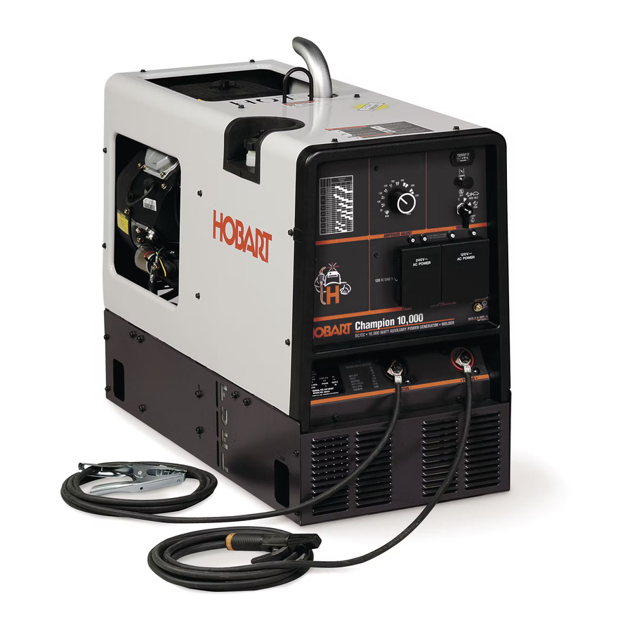
Hobart champion 10,000 welding machine
Hide thumbs
Also See for Champion 10,000:
- Specifications (4 pages) ,
- Owner's manual (69 pages) ,
- Manual (4 pages)

Subscribe to Our Youtube Channel
Related Manuals for Hobart Champion 10,000


Summary of Contents for Hobart Champion 10,000
- Page 1 OM-945 194 047B January 2000 Processes Stick (SMAW) Welding Description Engine Driven Welding Generator Champion 10,000 Visit our website at www.HobartWelders.com...
- Page 2 We know you don’t have time to do it any other way. This Owner’s Manual is designed to help you get the most out of your Hobart products. Please take time to read the Safety precautions. They will help you...
-
Page 3: Table Of Contents
TABLE OF CONTENTS SECTION 1 – SAFETY PRECAUTIONS - READ BEFORE USING ......1-1. Symbol Usage . -
Page 5: Section 1 - Safety Precautions - Read Before Using
SECTION 1 – SAFETY PRECAUTIONS - READ BEFORE USING rom _nd_11/98 1-1. Symbol Usage Means Warning! Watch Out! There are possible hazards with this procedure! The possible hazards are shown in the adjoining symbols. This group of symbols means Warning! Watch Out! possible Y Marks a special safety message. -
Page 6: Engine Hazards
WELDING can cause fire or explo- HOT PARTS can cause severe burns. sion. D Allow cooling period before maintaining. Welding on closed containers, such as tanks, D Wear protective gloves and clothing when drums, or pipes, can cause them to blow up. Sparks working on a hot engine. -
Page 7: Additional Symbols For Installation, Operation, And Maintenance
BATTERY ACID can BURN SKIN and MOVING PARTS can cause injury. EYES. D Keep away from fans, belts, and rotors. D Do not tip battery. D Keep all doors, panels, covers, and guards D Replace damaged battery. closed and securely in place. D Flush eyes and skin immediately with water. -
Page 8: Principal Safety Standards
H.F. RADIATION can cause interference. ARC WELDING can cause interference. D High-frequency (H.F.) can interfere with radio D Electromagnetic energy can interfere with navigation, safety services, computers, and sensitive electronic equipment such as communications equipment. computers and computer-driven equipment D Have only qualified persons familiar with such as robots. -
Page 9: Section 1 - Consignes De Sécurité - Lire Avant Utilisation
SECTION 1 – CONSIGNES DE SÉCURITÉ – LIRE AVANT UTILISATION rom _nd_fre 11/98 1-1. Signification des symboles Signifie Mise en garde ! Soyez vigilant ! Cette procédure présente des risques de danger ! Ceux-ci sont identifiés par des symboles adjacents aux directives. Ce groupe de symboles signifie Mise en garde ! Soyez vigilant ! Il y a des Y Identifie un message de sécurité... -
Page 10: Dangers Existant En Relation Avec Le Moteur
LE SOUDAGE peut provoquer un in- DES PIÈCES CHAUDES peuvent cendie ou une explosion. provoquer des brûlures graves. D Prévoir une période de refroidissement avant d’effec- Le soudage effectué sur des conteneurs fermés tels que tuer des travaux d’entretien. des réservoirs, tambours ou des conduites peut provoquer D Porter des gants et des vêtements de protection pour leur éclatement. -
Page 11: Dangers Supplémentaires En Relation Avec L'installation, Le Fonctionnement Et La Maintenance
DES ORGANES MOBILES peuvent L’ACIDE DE LA BATTERIE peut pro- provoquer des blessures. voquer des brûlures dans les YEUX et sur la PEAU. D Ne pas approcher les mains des ventilateurs, cour- roies et autres pièces en mouvement. D Ne pas renverser la batterie. D Maintenir fermés et fixement en place les portes, D Remplacer une batterie endommagée. -
Page 12: Principales Normes De Sécurité
LE RAYONNEMENT HAUTE FRÉ- LE SOUDAGE À L’ARC risque de QUENCE (H.F.) risque de provoquer provoquer des interférences. des interférences. D L’énergie électromagnétique risque de provoquer des interférences pour l’équipement électronique D Le rayonnement haute fréquence (H.F.) peut sensible tel que les ordinateurs et l’équipement com- provoquer des interférences avec les équipements mandé... -
Page 13: Section 2 - Definitions
SECTION 2 – DEFINITIONS 2-1. Symbol Definitions Fast Fast/Slow Stop Engine Slow (Idle) (Run, Weld/Power) (Run/Idle) Read Operator’s Start Engine Amperes Volts Manual Engine Oil Fuel Battery (Engine) Engine Check Valve Engine Choke Circuit Breaker Temperature Clearance Alternating Current Positive Negative Output (AC) -
Page 14: Dimensions, Weights, And Operating Angles
3-2. Dimensions, Weights, and Operating Angles Dimensions Height 33-1/2 in (851 mm) Width 18-1/2 in (470 mm) Y Do not exceed tilt angles or engine could Depth 38 in (965 mm) be damaged or unit could tip. Y Do not move or operate unit where it could 18 in (457 mm) tip. -
Page 15: Fuel Consumption (All Models)
3-4. Fuel Consumption (All Models) 197 254 3-5. Duty Cycle Duty cycle is the percentage of 10 minutes that unit can weld at rated load without overheating. Y Exceeding duty cycle can damage unit void warranty. Continuous Welding 100% Duty Cycle at 170 Amperes CC/DC 6 Minutes Welding 4 Minutes Resting 3 Minutes Welding... -
Page 16: Volt-Ampere Curves
3-6. Volt-Ampere Curves The volt-ampere curve shows the minimum and maximum voltage and amperage output capabilities of the welding generator. Curves of all other settings fall between the curves shown. 197 253 SECTION 4 – INSTALLATION 4-1. Installing Welding Generator Y Do not weld on base. -
Page 17: Engine Prestart Checks (Onan-Powered Units)
4-2. Engine Prestart Checks (Onan-Powered Units) Check all fluids daily. Engine must be cold and on a level surface. Unit is shipped with 10W30 engine oil. Engine stops if oil pressure gets too low. Follow run-in procedure in engine manual. Full This unit has a low oil pressure shut- Full... -
Page 18: Activating The Dry Charge Battery (If Applicable)
4-4. Activating The Dry Charge Battery (If Applicable) Remove battery from unit. Eye Protection – Safety Glasses Or Face Shield Rubber Gloves Vent Caps Sulfuric Acid Electrolyte (1.265 Specific Gravity) Well Fill each cell with electrolyte to bottom of well (maximum). Y Do not overfill battery cells. -
Page 19: Connecting The Battery
4-5. Connecting the Battery Y Connect negative (–) cable last. – Tools Needed: 1/2 in Ref. 194 024 / Ref. 802 341 / Ref. S-0756-D 4-6. Installing Exhaust Pipe Point exhaust pipe in desired direction. If unit is truck or trailer mounted, point pipe away from direction of travel. -
Page 20: Connecting To Weld Output Terminals
4-7. Connecting to Weld Output Terminals Negative (–) Weld Output Terminal Positive (+) Weld Output Terminal For Direct Current Electrode Posi- tive (DCEP), connect work cable to Negative (–) terminal and electrode holder cable Positive terminal. For Direct Current Electrode Nega- tive (DCEN), reverse... -
Page 21: Amperage Selection Table For Stick (Smaw) Electrodes
4-9. Amperage Selection Table For Stick (SMAW) Electrodes Use table on front panel to se- lect correct amperage for the electrode being used. Ref. 194 024 OM-945 Page 17... -
Page 22: Section 5 - Operating The Welding Generator
SECTION 5 – OPERATING THE WELDING GENERATOR NOTE If the unit is extremely overloaded, weld and auxiliary power will stop. Turn unit off and restart to reset the generator protection circuit and restore weld and auxiliary power output. If the rated output of the unit is exceeded, engine speed may vary rapidly until the weld or auxiliary power load is reduced. -
Page 23: Section 6 - Operating Auxiliary Equipment
SECTION 6 – OPERATING AUXILIARY EQUIPMENT NOTE If the unit is extremely overloaded, weld and auxiliary power will stop. Turn unit off and restart to reset the generator protection circuit and restore weld and auxiliary power output. If the rated output of the unit is exceeded, engine speed may vary rapidly until the weld or auxiliary power load is reduced. -
Page 24: Optional Auxiliary Power Receptacles
6-2. Optional Auxiliary Power Receptacles Y If unit does not have GFCI re- ceptacles, GFCI- protected extension cord. Combined output of all receptacles limited to 10 kVA/kW rating of the generator. GFCI Receptacle Option 120 V 20 A AC GFCI Recep- tacles GFCI2 and GFCI3 GFCI2 and GFCI3 supply 60 Hz single-phase power at weld/power... -
Page 25: Section 7 - Maintenance (Onan-Powered Units)
SECTION 7 – MAINTENANCE (ONAN-POWERED UNITS) 7-1. Maintenance Label (Onan-Powered Units) OM-945 Page 21... -
Page 26: Routine Maintenance (Onan-Powered Units)
7-2. Routine Maintenance (Onan-Powered Units) Note Follow the storage procedure in the engine owner’s manual if the unit will not be used for an extended period. Y Stop engine before maintaining. See also Engine Manual and maintenance label. Recycle Service engine more often if used in severe condi- engine tions. -
Page 27: Servicing Air Cleaner (Onan-Powered Units)
500 h Service welding generator Repair or brushes and slip rings. Service replace cracked more often in dirty conditions.* cables. Check valve clearance.* 1000 h Blow vacuum inside. During heavy service, clean monthly. 7-3. Servicing Air Cleaner (Onan-Powered Units) Y Stop engine. Y Do not run engine without air cleaner or with dirty element. -
Page 28: Overload Protection (Onan-Powered Units)
7-4. Overload Protection (Onan-Powered Units) Y Stop engine. Disconnect negative (–) battery cable. If the unit is extremely over- loaded, weld and auxiliary pow- er will stop. Turn unit off and re- start to reset the generator protection circuit and restore weld and auxiliary power out- put. -
Page 29: Changing Engine Oil, Oil Filter, And Fuel Filter (Onan-Powered Units)
7-6. Changing Engine Oil, Oil Filter, and Fuel Filter (Onan-Powered Units) Y Stop engine and let cool. Oil Drain Valve 1/2 ID x 7 in Hose Oil Filter Change engine oil and filter ac- cording to engine owner’s manual. Y Close valve and valve cap before adding oil and running engine. -
Page 30: Adjusting Engine Speed (Onan-Powered Units)
7-7. Adjusting Engine Speed (Onan-Powered Units) After tuning engine, check engine speeds with a tachometer (see table). If necessary, adjust speeds as follows: ± 2200 100 rpm Start engine and run until warm. ± Remove wrapper to access speed 3700 50 rpm adjustments. -
Page 31: Section 8 - Maintenance - (Kohler-Powered Units)
SECTION 8 – MAINTENANCE – (KOHLER-POWERED UNITS) 8-1. Maintenance Label (Kohler-Powered Units) OM-945 Page 27... -
Page 32: Routine Maintenance (Kohler-Powered Units)
8-2. Routine Maintenance (Kohler-Powered Units) Note Follow the storage procedure in the engine owner’s manual if the unit will not be used for an extended period. Y Stop engine before maintaining. See also Engine Manual and maintenance label. Recycle Service engine more often if used in severe condi- engine tions. -
Page 33: Servicing Air Cleaner (Kohler-Powered Units)
500 h Service welding generator Repair or replace cracked brushes and slip rings. Service cables. more often in dirty conditions.* 1000 h Blow out or vacuum inside. During heavy service, clean monthly. 8-3. Servicing Air Cleaner (Kohler-Powered Units) Y Stop engine. Y Do not run engine without air cleaner or with dirty element. -
Page 34: Overload Protection (Kohler-Powered Units)
8-4. Overload Protection (Kohler-Powered Units) Y Stop engine. If the unit is extremely over- loaded, weld and auxiliary pow- er will stop. Turn unit off and re- start to reset the generator protection circuit and restore weld and auxiliary power out- put. -
Page 35: Changing Engine Oil, Oil Filter, And Fuel Filter (Kohler-Powered Units)
8-6. Changing Engine Oil, Oil Filter, and Fuel Filter (Kohler-Powered Units) Y Stop engine and let cool. Oil Drain Valve 1/2 ID x 7 in Hose Oil Filter Change engine oil and filter accord- ing to engine owner’s manual. Y Close valve and valve cap before adding running engine. -
Page 36: Adjusting Engine Speed (Kohler-Powered Units)
8-7. Adjusting Engine Speed (Kohler-Powered Units) After tuning engine, check engine speeds with a tachometer (see table). If necessary, adjust speeds as follows: ± 2200 50 rpm Start engine and run until warm. Remove wrapper to access speed ± 3700 50 rpm adjustments. -
Page 37: Section 9 - Troubleshooting
SECTION 9 – TROUBLESHOOTING 9-1. Troubleshooting A. Welding Trouble Remedy No weld output. Check control settings. Check weld connections. Check fuse F1 and replace if open (see Section 7-4 or 8-4). Unit overloaded. Stop unit and reduce load. Restart unit to reset generator protection circuit and resume operation. - Page 38 Trouble Remedy Erratic power output. Check fuel level. Check engine speed and adjust if necessary (see Section 7-7 or 8-7). Check receptacle wiring and connections. Have Factory Authorized Service Agent check brushes and slip rings. C. Engine Trouble Remedy Engine will not crank. Check fuse F6, and replace if open (see Section 7-4 or 8-4).
-
Page 39: Section 10 - Electrical Diagrams
SECTION 10 – ELECTRICAL DIAGRAMS 196 661 Figure 10-1. Circuit Diagram For Welding Generator (Onan-Powered Units) OM-945 Page 35... - Page 40 196 663 Figure 10-2. Circuit Diagram For Welding Generator (Kohler-Powered Units) OM-945 Page 36...
-
Page 41: Section 11 - Auxiliary Power Guidelines
SECTION 11 – AUXILIARY POWER GUIDELINES 11-1. Selecting Equipment Auxiliary Power Receptacles – Neutral Bonded To Frame 3-Prong Plug From Case Grounded Equipment 2-Prong Plug From Double Insulated Equipment Be sure equipment has this symbol and/or wording. aux_pwr 2/99 – Ref. ST-159 730 / ST-800 577 11-2. -
Page 42: Grounding When Supplying Building Systems
11-3. Grounding When Supplying Building Systems Equipment Grounding Terminal Grounding Cable GND/PE Use #10 AWG or larger insulated copper wire. Ground Device Y Ground generator to system earth ground if supplying power to a premises (home, shop, farm) wiring system. Use ground device as stated in electrical codes. - Page 43 11-5. Approximate Power Requirements For Industrial Motors Industrial Motors Rating Starting Watts Running Watts Split Phase 1/8 HP 1/6 HP 1225 1/4 HP 1600 1/3 HP 2100 1/2 HP 3175 Capacitor Start-Induction Run 1/3 HP 2020 1/2 HP 3075 3/4 HP 4500 1400 1 HP...
- Page 44 11-7. Approximate Power Requirements For Contractor Equipment Contractor Rating Starting Watts Running Watts Hand Drill 1/4 in 3/8 in 1/2 in Circular Saw 6-1/2 in 7-1/4 in 8-1/4 in 1400 1400 Table Saw 9 in 4500 1500 10 in 6300 1800 Band Saw 14 in...
- Page 45 11-8. Power Required To Start Motor Motor Start Code AC MOTOR Running Amperage VOLTS AMPS Motor HP CODE Motor Voltage PHASE To find starting amperage: Step 1: Find code and use table to find kVA/HP. If code is not listed, multiply running amperage by six to find starting amperage.
- Page 46 11-10. Typical Connections To Supply Standby Power Power Company Service Meter Main and Branch Overcurrent Protection Double-Pole, Double-Throw Transfer Switch Obtain and install correct switch. Switch rating must be same as or Customer-supplied equipment is required if greater than the branch overcurrent generator is to supply standby power during protection.
- Page 47 11-11. Selecting Extension Cord (Use Shortest Cord Possible) Cord Lengths for 120 Volt Loads Y If unit does not have GFCI receptacles, use GFCI-protected extension cord. Maximum Allowable Cord Length in ft (m) for Conductor Size (AWG)* Current Load (Watts) (Amperes) 350 (106) 225 (68)
-
Page 48: Section 12 - Stick Welding (Smaw) Guidelines
SECTION 12 – STICK WELDING (SMAW) GUIDELINES 12-1. Stick Welding Procedure Y Weld current starts when electrode touches work- piece. Y Weld current can damage electronic parts in vehicles. Disconnect both battery cables before welding on a vehicle. Place work clamp as close to the weld as possible. -
Page 49: Electrode And Amperage Selection Chart
12-2. Electrode and Amperage Selection Chart 3/32 6010 5/32 & 3/16 6011 7/32 6010 DEEP MIN. PREP, ROUGH 1/16 HIGH SPATTER 6011 DEEP 5/64 6013 EP,EN GENERAL 3/32 SMOOTH, EASY, 6013 7014 EP,EN FAST 5/32 3/16 LOW HYDROGEN, 7018 STRONG 7/32 FLAT SMOOTH, EASY,... -
Page 50: Positioning Electrode Holder
12-5. Positioning Electrode Holder ° ° ° ° End View of Work Angle Side View of Electrode Angle GROOVE WELDS ° ° ° ° End View of Work Angle Side View of Electrode Angle FILLET WELDS S-0060 12-6. Poor Weld Bead Characteristics Large Spatter Deposits Rough, Uneven Bead Slight Crater During Welding... -
Page 51: Conditions That Affect Weld Bead Shape
12-8. Conditions That Affect Weld Bead Shape NOTE Weld bead shape is affected by electrode angle, arc length, travel speed, and thickness of base metal. Correct Angle ° - ° Angle Too Large Angle Too Small Drag ELECTRODE ANGLE Spatter Normal Too Long Too Short... -
Page 52: Butt Joints
12-10. Butt Joints Tack Welds Prevent edges of joint from drawing together ahead of electrode by tack welding the materials in position be- fore final weld. Square Groove Weld Good for materials up to 3/16 in (5 mm) thick. Single V-Groove Weld °... -
Page 53: Weld Test
12-13. Weld Test Vise Weld Joint Hammer Strike weld joint in direction shown. A good weld bends over but does not break. 2 To 3 in (51-76 mm) 2 To 3 in (51-76 mm) 1/4 in (6.4 mm) S-0057-B 12-14. Troubleshooting – Porosity Porosity –... -
Page 54: Troubleshooting – Incomplete Fusion
12-16. Troubleshooting – Incomplete Fusion Incomplete Fusion – failure of weld metal to fuse completely with base metal or a preceeding weld bead. Possible Causes Corrective Actions Insufficient heat input. Increase amperage. Select larger electrode and increase amperage. Improper welding technique. Place stringer bead in proper location(s) at joint during welding. -
Page 55: Troubleshooting – Burn-Through
12-19. Troubleshooting – Burn-Through Burn-Through – weld metal melting completely through base metal resulting in holes where no metal remains. Possible Causes Corrective Actions Excessive heat input. Select lower amperage. Use smaller electrode. Increase and/or maintain steady travel speed. 12-20. Troubleshooting – Waviness Of Bead Waviness Of Bead –... -
Page 56: Section 13 - Parts List
SECTION 13 – PARTS LIST Hardware is common and not available unless listed. Kohler only 49 – Fig 13-2 20 – Fig 13–3 802 343-B Figure 13-1. Main Assembly (Onan Engine Shown) OM-945 Page 52... - Page 57 Item Dia. Part Mkgs. Description Quantity Figure 13-1. Main Assembly ....+193 777 Wrapper, ........... .
- Page 58 Item Dia. Part Mkgs. Description Quantity Figure 13-1. Main Assembly (Continued) ..197 514 ..Rectifier, Si 1ph 280 Amp 400 Piv 60% Duty Cycle ....
- Page 59 Item Dia. Part Mkgs. Description Quantity Figure 13-2. Panel, Front w/Components (Figure 13-1 Item 49) ......Nameplate (order by model &...
- Page 60 Item Part Description Quantity Figure 13-3. Generator (Figure 13-1 Item 20) ....+194 621 Housing, Generator Front (consisting of) ......
- Page 63 5/3/1 WARRANTY applies to all Handler 135 and 175 models, Airforce 250, 250A, and 375 Warranty Questions? models, and Champion 10,000 models.This warranty also applies to the Beta-Mig 1800, Champ Call 1435, 2060, 8500 models, Ironman 250, Stickmate models, Tigmate models, and HSW-15 and 1-877-HOBART1 HSW-25 spot welder models effective with Serial No.
-
Page 64: Options And Accessories
Call 1-877-Hobart1 Contact the Delivering Carrier for: File a claim for loss or damage during shipment. For assistance in filing or settling claims, contact your distributor and/or equipment manufacturer’s Transportation Department. PRINTED IN USA 2000 Hobart Welding Products. 1/00...
Need help?
Do you have a question about the Champion 10,000 and is the answer not in the manual?
Questions and answers