Hobart Handler 140 Technical Manual
Hide thumbs
Also See for Handler 140:
- Owner's manual (48 pages) ,
- Specifications (4 pages) ,
- Owner's manual (44 pages)
Table of Contents
Troubleshooting

Related Manuals for Hobart Handler 140


Summary of Contents for Hobart Handler 140
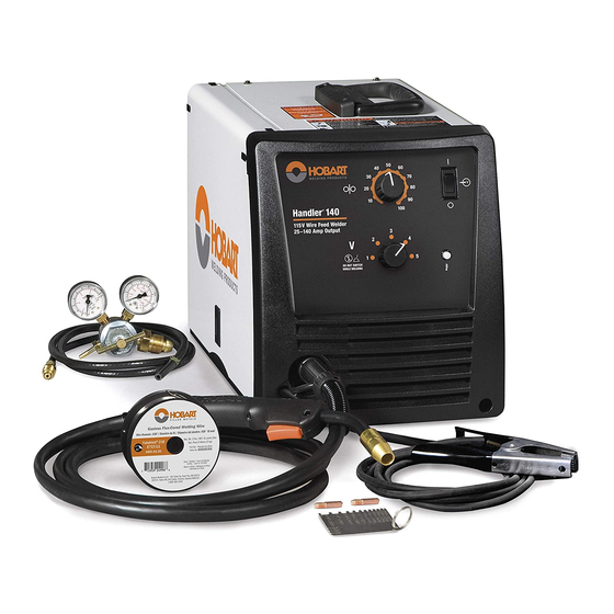
- Page 1 TM-258 267B 2013−03 Eff. w/Serial No. MC370275Y Processes MIG (GMAW) Welding Flux Cored (FCAW) Welding Description Arc Welding Power Source And Wire Feeder Handler 140 And H100S2-10 Gun File: MIG (GMAW) www.HobartWelders.com...
-
Page 2: Table Of Contents
............Hobart is registered to the ISO 9001 Quality 8-6. -
Page 3: Section 1 − Safety Precautions For Servicing
D Do not place unit on, over, or near combustible D Follow the guidelines in the Applications Manual for the Revised surfaces. NIOSH Lifting Equation (Publication No. 94−110) when manu- D Do not service unit near flammables. ally lifting heavy parts or equipment. Handler 140 TM-258 267 Page 1... -
Page 4: California Proposition 65 Warnings
If cleared by your doctor, then following the above procedures is recom- 3. Do not coil or drape cables around your body. mended. TM-258 267 Page 2 Handler 140... -
Page 5: Section 2 − Definitions
.030 − .035 in. .030 in. 50 − 740 IPM (1.3 − 18.8 m/min) At No Load (0.6 − 0.9 mm) (0.8 − 0.9 mm) (0.8 mm) 40 − 700 IPM (1.0 − 17.8 m/min) Feeding Wire Handler 140 TM-258 267 Page 3... -
Page 6: Duty Cycle And Overheating
Curves of other settings fall between the curves shown. RANGE 5 RANGE 4 RANGE 3 RANGE 2 RANGE 1 Amperage ssb1.1 10/91 − 257 981-A TM-258 267 Page 4 Handler 140... -
Page 7: Section 4 − Installation
(460 mm) Plug From Unit Grounded Receptacle Special installation Locate unit near correct input power required where gasoline or volatile supply. liquids are present − see NEC Article 511 or CEC Section 20. 258 641-A Handler 140 TM-258 267 Page 5... -
Page 8: Installing Welding Gun
A loose electrical connection will cause poor weld performance and excessive heating of the work clamp. Screw Flat Washer Lock Washer Route work cable through hole in clamp handle. Secure cable with hardware as shown. Tools Needed: 10 mm 258 550-A TM-258 267 Page 6 Handler 140... -
Page 9: Process/Polarity Table
4-5. Changing Polarity Lead Connections For Direct Current Electrode Negative (DCEN) Lead Connections For Direct Current Electrode Positive (DCEP) Always read and follow wire manufacturer’s recommended polarity, and see Section 4-4. Close door. 258 321-A Handler 140 TM-258 267 Page 7... -
Page 10: Installing Gas Supply
Typical flow rate is 20 cfh (cubic feet hour). Check wire manufacturer’s recommended flow rate. After flow is set, close pressure assembly. Tools Needed: 5/8 or 11/16, 1-1/8 in. Feedhead Pressure Assembly Open Feedhead Pressure Assembly Closed 258 331-B TM-258 267 Page 8 Handler 140... -
Page 11: Connecting Input Power
Conductor Size − AWG (mm Single Phase AC 10 (5.3) 12 (3.3) Input Voltage Maximum Allowable Cord Length in ft (m) 100 (30.5) 50 (15.0) *Conductor size is based on maximum 3% voltage drop Handler 140 TM-258 267 Page 9... -
Page 12: Installing Wire Spool And Adjusting Hub Tension
Align locking hole in spool with locking pin on spool hub. Retaining ring used with 8 in. (203 mm) spool only. Tools Needed: 1/2 in. 803 012 / 803 013 -B / Ref. 802 971-C TM-258 267 Page 10 Handler 140... -
Page 13: Installing Contact Tip And Nozzle
Push nozzle over contact tip and adapter until it is seated onto adapter. Contact tip will be exposed approximately 7/16 in. (11.3 mm) when installed properly. Tools Needed: Ref. 246 669-A Handler 140 TM-258 267 Page 11... -
Page 14: Threading Welding Wire
(see Section 8-4). 4 in. (102 mm) Straighten approximately 3 or 4 inches (76 or 102 mm) of wire before inserting wire into guides. Push wire thru guides into gun; continue to hold wire. TM-258 267 Page 12 Handler 140... - Page 15 (102 To 152 mm) WOOD Be sure that tip matches wire diameter. Feed wire to check drive roll pressure. Reinstall contact tip and nozzle. Tighten knob enough to prevent slipping. Cut off wire. Close door. 258 339-A Handler 140 TM-258 267 Page 13...
-
Page 16: Section 5 − Operation
Section 5-2). Switch must “click” into detent Pressing gun trigger energizes wire feed Power Switch position for weld output. motor and gas valve for shielding gas flow. TM-258 267 Page 14 Handler 140... -
Page 17: Weld Parameter Chart
5-2. Weld Parameter Chart 258 069-A Handler 140 TM-258 267 Page 15... -
Page 18: Section 6 − Theory Of Operation
12 Main Transformer T1 Supplies power to weld output circuit. 13 Rectifier SR1 Changes the AC output from T1 to full-wave rectified DC output. TM-258 267 Page 16 Handler 140... - Page 19 Rectifier SR1 Main Transformer Capacitor C1 Stablizer L1 Polarity Changeover Block Thermostat Welding Wire Gun Trigger (Electrode) Receptacle RC3 Work Wire Speed Control R2 Wire Drive Motor AC Or DC Control Circuits Weld Current Circuit Handler 140 TM-258 267 Page 17...
-
Page 20: Section 7 − Troubleshooting
Check T1 for signs of winding failure. Check continuity across each winding and check for proper connections. Check secondary voltages. Replace T1 if necessary. Check Control board PC1 and connections, and replace PC1 if necessary (see Section 7-3). TM-258 267 Page 18 Handler 140... - Page 21 Clean or replace gas hose. Check shielding gas valve GS1 for proper coil voltage and connections. Check continuity of coil. Replace GS1 if necessary. Clear blockage in gun. Shielding gas flows continuously. Replace contactor CR3. Handler 140 TM-258 267 Page 19...
-
Page 22: Troubleshooting Circuit Diagram For Welding Power Source
7-2. Troubleshooting Circuit Diagram For Welding Power Source V6,R6 V7,R7 See also Section 7-3 for PC1 data Test Equipment Needed: TM-258 267 Page 20 Handler 140... - Page 23 R2 from min. to max. with Voltage switch S2 in position 4 5.9 to 23.6 volts DC with unit turned on, Wire Speed control R2 from min. to max. with Voltage switch S2 in position 5 230 952-A Handler 140 TM-258 267 Page 21...
-
Page 24: Control Board Pc1 Testing Information (Use With Section 7-4)
7-3. Control Board PC1 Testing Information (Use With Section 7-4) Be sure plugs are secure before Test Equipment Needed: testing. See Section 7-4 for specific values during testing. Control Board PC1 803 717-A / 256 988-A TM-258 267 Page 22 Handler 140... -
Page 25: Control Board Pc1 Test Point Values
24 volts AC with gun trigger open 11 − 12 24 volts AC with gun trigger closed 29 volts DC, reference to Pin 5 29 volts DC, reference to Pin 5 29 volts DC, reference to Pin 5 Not used Handler 140 TM-258 267 Page 23... -
Page 26: Section 8 − Maintenance
8-3. Drive Motor Protection Drive motor protection circuit protects drive motor from overload. If drive motor becomes inoperative, release gun trigger and wait until protection circuit resets allowing drive motor to feed wire again. TM-258 267 Page 24 Handler 140... -
Page 27: Changing Drive Roll Or Wire Inlet Guide
8-5. Replacing Gun Contact Tip Turn power before replacing contact tip. Nozzle Contact Tip Cut off welding wire at contact tip. Remove nozzle. Remove contact tip and install new contact tip. Reinstall nozzle. Tools Needed: Ref. 246 669-A Handler 140 TM-258 267 Page 25... -
Page 28: Cleaning Or Replacing Gun Liner
Cut liner off so that 3/4 in. (19 mm) sticks out of head tube. Install gas diffuser, adapter, contact tip, and nozzle. Tools Needed: 8 mm / 10mm Ref. 246 669-A TM-258 267 Page 26 Handler 140... -
Page 29: Replacing Switch And/Or Head Tube
Hand-tighten head tube into cable connector. Place head tube in vice and tighten until nuts are tight. Install handle half with secure with screws. Remove from vice. install switch housing. Tools Needed: 19 mm Ref. 243 840-A Handler 140 TM-258 267 Page 27... - Page 30 Notes TM-258 267 Page 28 Handler 140...
-
Page 31: Section 9 − Electrical Diagrams
Serial Or Style Number Circuit Diagram Wiring Diagram Welding Power Source MC370275YAnd following 257 502-A 257 500-A Circuit Board PC1 MC370275Y and following 256 987-A (115 VAC Model) Not included in this manual Handler 140 TM-258 267 Page 29... - Page 32 Figure 9-1. Circuit Diagram Eff w/MC370275Y And Following TM-258 267 Page 30 Handler 140...
- Page 33 257 502-A Handler 140 TM-258 267 Page 31...
- Page 34 Figure 9-2. Wiring Diagram Eff w/MC370275Y And Following TM-258 267 Page 32 Handler 140...
- Page 35 257 500-A Handler 140 TM-258 267 Page 33...
- Page 36 +30V +29V AGND +29V +30V PTC2 +29V AGND AGND AGND Figure 9-3. Circuit Diagram For 115 VAC Model Control Board PC1 Eff w/MC370275Y And Following TM-258 267 Page 34 Handler 140...
- Page 37 VOUT CAP + 5AMP_50V CAP − AGND 5AMP_50V HEATSINK VERTICAL MOTOR + 5AMP_50V MOTOR − AGND VOUT WFS_REF AGND 256 987-A Handler 140 TM-258 267 Page 35...
- Page 38 Notes TM-258 267 Page 36 Handler 140...
- Page 39 TM-258 267B 2013−03 Eff. w/Serial No. MC370275Y Processes MIG (GMAW) Welding Flux Cored (FCAW) Welding Description Arc Welding Power Source And Wire Feeder Handler 140 And H100S2-10 Gun File: MIG (GMAW) www.HobartWelders.com...
-
Page 40: Section 10 − Parts List
SECTION 10 − PARTS LIST Hardware is common and not available unless listed. 258 385-A Figure 10-1. Main Assembly TM-258 267 Page 38 Handler 140... - Page 41 +When ordering a component originally displaying a precautionary label, the label should also be ordered. To maintain the factory original performance of your equipment, use only Manufacturer’s Suggested Replacement Parts. Model and serial number required when ordering parts from your local distributor. TM-258 267 Page 39 Handler 140...
- Page 42 ....To maintain the factory original performance of your equipment, use only Manufacturer’s Suggested Replacement Parts. Model and serial number required when ordering parts from your local distributor. TM-258 267 Page 40 Handler 140...
- Page 43 ........OPTIONAL To maintain the factory original performance of your equipment, use only Manufacturer’s Suggested Replacement Parts. Model and serial number required when ordering parts from your local distributor. TM-258 267 Page 41 Handler 140...
-
Page 44: Section 11 − Accessories And Consumables
196 139 194 011 .035/.045 in (0.9/1.2 mm) 196 140 194 012 *Available at farm and tool supply retailers. ** Available at Hobart/Miller welding distributors. 11-3. Replacement Drive Rolls For All Feed Head Assemblies WIRE DIAMETER PART NO. INCHES (mm) 237 338 .023/.025 (.6) and .030/.035 (.8 and .9) - Page 45 Notes...
- Page 46 Notes...
- Page 47 Notes Work like a Pro! Pros weld and cut safely. Read the safety rules at the beginning of this manual.
- Page 48 Hobart Brothers Co. An Illinois Tool Works Company 600 West Main Street Troy, OH 45373 USA For Assistance: Call1-800-332-3281 ORIGINAL INSTRUCTIONS − PRINTED IN USA 2013 Hobart Brothers Co. 2013−01...
Need help?
Do you have a question about the Handler 140 and is the answer not in the manual?
Questions and answers