Table of Contents
Troubleshooting

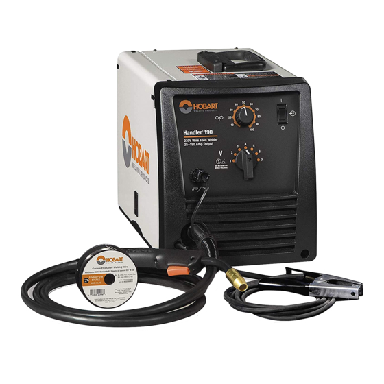
Related Manuals for Hobart Handler 190


Summary of Contents for Hobart Handler 190
- Page 1 TM-260 273B 2013−02 Eff. w/Serial No. MC420249Y Processes MIG (GMAW) Welding Flux Cored (FCAW) Welding Description Arc Welding Power Source And Wire Feeder Handler 190 And H100S4-10 Gun File: MIG (GMAW) www.HobartWelders.com...
-
Page 2: Table Of Contents
..........Hobart is registered to the ISO 9001 Quality 7-5. -
Page 3: Section 1 − Safety Precautions For Servicing
D Do not place unit on, over, or near combustible D Follow the guidelines in the Applications Manual for the Revised surfaces. NIOSH Lifting Equation (Publication No. 94−110) when manu- D Do not service unit near flammables. ally lifting heavy parts or equipment. Handler 190 TM-260 273 Page 1... -
Page 4: California Proposition 65 Warnings
If cleared by your doctor, then following the above procedures is recom- 3. Do not coil or drape cables around your body. mended. TM-260 273 Page 2 Handler 190... -
Page 5: Section 2 − Specifications
60 70 80 D u t y C ycl e % 30% duty cycle at 130 amps 3 Minutes Welding 7 Minutes Resting Overheating A or V Reduce Duty Cycle Minutes duty1 4/95 − 248 832-A Handler 190 TM-260 273 Page 3... -
Page 6: Volt-Ampere Curves
3-1. Installing Nozzle, Contact Tip, And Adapter Turn off welding power source. Nozzle Contact Tip Tip Adapter Head Wire size stamped on tip − check Tube and match wire size. 8 mm Tools Needed: 8 mm Ref. 243 839-A TM-260 273 Page 4 Handler 190... -
Page 7: Installing Welding Gun
Place switch in MIG Gun position. Close door. Be sure that gun end is tight against drive assembly. Correct Exposed O-rings Incorrect will cause shielding Gun Fully Seated Gun Not Seated gas leakage. 260 458-A Handler 190 TM-260 273 Page 5... -
Page 8: Installing Work Clamp
Route work cable through hole in and excessive heating of the work clamp. clamp handle. Secure cable with hardware as shown. Tools Needed: 10 mm 258 550-A TM-260 273 Page 6 Handler 190... -
Page 9: Process/Polarity Table
Lead Connections For Direct DCEN Current Electrode Positive Electrode negative (DCEP) for flux cored wire Always read and follow wire manufacturer’s recommended polarity, and see Section 3-4. Close door. DCEP Electrode positive for solid wire 260 459-A Handler 190 TM-260 273 Page 7... -
Page 10: Installing Gas Supply
Typical flow rate is 20 cfh (cubic Mixed Gas feet hour). Check wire manufacturer’s recommended flow rate. After flow is set, close pressure assembly. Pressure Assembly Pressure Assembly Open Closed Tools Needed: 5/8 or 11/16, 1-1/8 in. 260 460-A TM-260 273 Page 8 Handler 190... -
Page 11: Serial Number And Rating Label Location
− see NEC Article 511 or CEC Section 20. Do not move or operate unit where it could tip. 18 in (460 mm) 18 in (460 mm) 260 711-B / ST-139 445-E Handler 190 TM-260 273 Page 9... -
Page 12: Installing Wire Spool And Adjusting Hub Tension
When a slight force is needed to turn spool, tension is set. Retaining ring used with 8 in. (203 mm) spool only. Tools Needed: 1/2 in. 803 012 / 803 013 -B / Ref. 802 971-C TM-260 273 Page 10 Handler 190... -
Page 13: Electrical Service Guide
4 Conductor data in this section specifies conductor size (excluding flexible cord or cable) between the panelboard and the equipment per NEC Table 310.15(B)(16). If a flexible cord or cable is used, minimum conductor size may increase. See NEC Table 400.5(A) for flexible cord and cable requirements. Handler 190 TM-260 273 Page 11... -
Page 14: Connecting Input Power
3-11. Connecting Input Power =GND/PE Earth Ground 230 VAC, 1 Tools Needed: input4 2012−05 − Ref. 803 766-C / 260 711-A TM-260 273 Page 12 Handler 190... - Page 15 Connect plug to receptacle. input4 2012−05 − 803 766-C / 260 711-A Notes Work like a Pro! Pros weld and cut safely. Read the safety rules at the beginning of this manual. Handler 190 TM-260 273 Page 13...
-
Page 16: Connecting Optional Spool Gun
Incorrect Correct 10 Trigger Gun Not Seated Gun Fully Seated Press trigger to energize welding power source contactor, start shielding gas flow, and begin wire feed. 260 573-A TM-260 273 Page 14 Handler 190... -
Page 17: Threading Welding Wire
Be sure that tip matches wire diameter. Press gun trigger until wire comes Tighten knob enough to prevent slipping. Reinstall contact tip and nozzle. out of gun. Cut off wire. Close door. 260 587-A Handler 190 TM-260 273 Page 15... -
Page 18: Section 4 − Operation
(see weld shielding gas flows. source or Section 4-2, as applicable). Do setting label in welding power source or not switch under load. Section 4-2, as applicable). Switch must “click” into detent Power Switch position. TM-260 273 Page 16 Handler 190... -
Page 19: Weld Parameter Chart For 230 Vac Model
4-2. Weld Parameter Chart For 230 VAC Model 248 827-B Handler 190 TM-260 273 Page 17... -
Page 20: Section 5 − Theory Of Operation
PC1. 13 Rectifier SR1 Changes the ac output from T1 to full-wave rectified dc output. 14 Output Capacitor C1 Smooths dc weld voltage from rectifier SR1. 15 Stabilizer Z1 Smooths dc weld current. TM-260 273 Page 18 Handler 190... - Page 21 Changeover Block Thermostat Welding Wire Gun Trigger (Electrode) Receptacle RC7 Work Wire Speed Control R2 Integrated Wire Drive Motor Spool Gun Wire Drive Motor AC Or DC Control Circuits TM-260273 Page Weld Current Circuit Handler 190 TM-260 273 Page 19...
-
Page 22: Section 6 − Troubleshooting
Check and clear any restrictions at drive assembly and liner (see Section 7-4 and/or 7-5). Check T1 for signs of winding failure. Check continuity across each winding and check for proper connections. Check secondary voltages. Replace T1 if necessary. TM-260 273 Page 20 Handler 190... - Page 23 Check O-rings on gun connector and replace if damaged. Make sure inner head tube is tight in cable connector. Check gun connector to be sure it is fully inserted into drive assembly. Check shielding gas flow/supply. Handler 190 TM-260 273 Page 21...
-
Page 24: Troubleshooting Circuit Diagram For Welding Power Source
*All tests done with .030-.035 liner in H-10 model 10 open, not feeding wire. Values are nominal. foot welding gun, smooth groove drive roll. Values are nominal depending on drive roll pressure and spool hub tension. TM-260 273 Page 22 Handler 190... - Page 25 5 and gun trigger closed 28.1 volts dc with Voltage switch S2 in position 6 and gun trigger closed 30.3 volts dc with Voltage switch S2 in position 7 and gun trigger closed 228 180-A Handler 190 TM-260 273 Page 23...
-
Page 26: Control Board Pc1 Testing Information
6-3. Control Board PC1 Testing Information Be sure plugs are secure before testing. See Section 6-4 for specific values during testing. Control Board PC1 Receptacle RC1 Receptacle RC4 Test Equipment Needed: Ref. 804 691-A / 248 284-A TM-260 273 Page 24 Handler 190... -
Page 27: Control Board Pc1 Test Point Values
0 volts dc with gun trigger open +1.9 volts dc with Wire Speed control R2 set to min and gun trigger closed +14.4 volts dc with Wire Speed control R2 set to max and gun trigger closed Handler 190 TM-260 273 Page 25... -
Page 28: Section 7 − Maintenance
7-3. Drive Motor Protection Drive motor protection circuit protects drive motor from overload. If drive motor becomes inoperative, release gun trigger and wait until protection circuit resets allowing drive motor to feed wire again. TM-260 273 Page 26 Handler 190... -
Page 29: Changing Drive Roll Or Wire Inlet Guide
Solid Wire − Recommended stickout is 3/8 in. Stamped (9.5 mm) from gun tip. .030/.035 Stamped .030/.035 V VK Grooved Actual drive roll may differ from that shown. See Section 9-4 for additional drive roll configurations. 258 380-B Handler 190 TM-260 273 Page 27... -
Page 30: Changing Nozzle, Contact Tip, Adapter And Liner, And Cleaning Gun Casing
Reassemble gun in reverse order from taking it apart. Install 5/8 in. Liner (16 mm) Liner Stickout Thread wire according to welding power source/wire feeder manual. Tools Needed: 8 mm, 10 mm 243 839-A TM-260 273 Page 28 Handler 190... -
Page 31: Replacing Switch And/Or Head Tube
Hand-tighten head tube into cable connector. nuts are tight. Reinstall screws Remove from vice. Reposition handle halves, and and nuts. install switch housing. Reinstall screw on opposite side. Tools Needed: 15 mm phillips 243 840-A Handler 190 TM-260 273 Page 29... - Page 32 Notes TM-260 273 Page 30 Handler 190...
-
Page 33: Section 8 − Electrical Diagrams
Model Serial Or Style Number Circuit Diagram Wiring Diagram Welding Power Source MC420249Y and following 248 830-A 248 831-A ♦♦ Circuit Board PC1 MC420249Y and following 248 286-A ♦♦ Not included in this manual Handler 190 TM-260 273 Page 31... - Page 34 Figure 8-1. Circuit Diagram For Welding Power Source Eff. w/MC420249Y And Following TM-260 273 Page 32 Handler 190...
- Page 35 248 830-A Handler 190 TM-260 273 Page 33...
- Page 36 Figure 8-2. Wiring Diagram For Welding Power Source Eff. w/MC420249Y And Following TM-260 273 Page 34 Handler 190...
- Page 37 248 831-A Handler 190 TM-260 273 Page 35...
- Page 38 AGND +29V 20PIN 20PIN +30V +t’ PTC2 20PIN +29V AGND 20PIN 20PIN AGND 20PIN 20PIN +30V 13 RC1 20PIN AGND 20PIN AGND Figure 8-3. Circuit Diagram For Control Board PC1 Eff. w/MC420249Y And Following TM-260 273 Page 36 Handler 190...
- Page 39 VOUT CAP + 5AMP_50V 20PIN CAP − 20PIN AGND 5AMP_50V HEATSINK 5AMP_50V 20PIN MOTOR + 5AMP_50V 2PIN 5AMP_50V 20PIN 5AMP_50V 5AMP_50V MOTOR − VOUT 2PIN AGND +29V 20PIN WFS_REF 20PIN 20PIN AGND 248 286-A Handler 190 TM-260 273 Page 37...
- Page 40 Notes TM-260 273 Page 38 Handler 190...
- Page 41 TM-260 273B 2013−02 Eff. w/Serial No. MC420249Y Processes MIG (GMAW) Welding Flux Cored (FCAW) Welding Description Arc Welding Power Source And Wire Feeder Handler 190 And H100S4-10 Gun File: MIG (GMAW) www.HobartWelders.com...
-
Page 42: Section 9 − Parts List
SECTION 9 − PARTS LIST Hardware is common and not available unless listed. 258 438-A Figure 9-1. Main Assembly TM-260 273 Page 40 Handler 190... - Page 43 +When ordering a component originally displaying a precautionary label, the label should also be ordered. To maintain the factory original performance of your equipment, use only Manufacturer’s Suggested Replacement Parts. Model and serial number required when ordering parts from your local distributor. Handler 190 TM-260 273 Page 41...
- Page 44 +When ordering a component originally displaying a precautionary label, the label should also be ordered. To maintain the factory original performance of your equipment, use only Manufacturer’s Suggested Replacement Parts. Model and serial number required when ordering parts from your local distributor. TM-260 273 Page 42 Handler 190...
- Page 45 ....To maintain the factory original performance of your equipment, use only Manufacturer’s Suggested Replacement Parts. Model and serial number required when ordering parts from your local distributor. Handler 190 TM-260 273 Page 43...
- Page 46 ........+OPTIONAL To maintain the factory original performance of your equipment, use only Manufacturer’s Suggested Replacement Parts. Model is required when ordering parts from your local distributor. TM-260 273 Page 44 Handler 190...
-
Page 47: Optional Drive Rolls
.023/.025 in (0.6 mm) 196 139 194 010 .030/.035 in (0.8/0.9 mm) 196 139 194 011 .035/.045 in (0.9/1.2 mm) 196 140 194 012 *Available at farm and tool supply retailers. **Available at Hobart/Miller welding distributors. Handler 190 TM-260 273 Page 45... - Page 48 Hobart Brothers Co. An Illinois Tool Works Company 600 West Main Street Troy, OH 45373 USA For Assistance: Call1-800-332-3281 © ORIGINAL INSTRUCTIONS − PRINTED IN USA 2013 Hobart Brothers Co. 2013−01...
Need help?
Do you have a question about the Handler 190 and is the answer not in the manual?
Questions and answers