Yamaha MG10/2 Service Manual
Mixing console
Hide thumbs
Also See for MG10/2:
- Owner's manual (28 pages) ,
- Service manual (48 pages) ,
- Service manual (47 pages)
Table of Contents
Advertisement
011679
PA
200306-14800
SERVICE MANUAL
CONTENTS
Circuit Board LAYOUT & WIRING
CIRCUIT BOARD
....................................................... 17/21
PARTS LIST
BLOCK DIAGRAM & LEVEL DIAGRAM
Copyright (c) Yamaha Corporation. All rights reserved. PDF-K135
................................................ 3/5
............................................................ 7
..................................... 8
............................................ 11
............................ 12
.................................. 14
......................................... 15
HAMAMATSU, JAPAN
MG10/2
1
'03.04
Advertisement
Table of Contents

Related Manuals for Yamaha MG10/2


Summary of Contents for Yamaha MG10/2
- Page 1 ..........11 DISASSEMBLY PROCEDURE ......12 IC BLOCK DIAGRAM ........14 CIRCUIT BOARD ......... 15 INSPECTIONS ............17/21 PARTS LIST BLOCK DIAGRAM & LEVEL DIAGRAM OVERALL CIRCUIT DIAGRAM 011679 HAMAMATSU, JAPAN 200306-14800 Copyright (c) Yamaha Corporation. All rights reserved. PDF-K135 ’03.04...
- Page 2 IMPOR TANT NOTICE This manual has been provided for the use of authorized Yamaha Retailers and their service personnel. It has been assumed that basic service procedures inherent to the industry, and more specifically Yamaha Products, are already known and under- stood by the users, and have therefore not been restated.
-
Page 3: Specifications
MG10/2 SPECIFICATIONS General Specifications Ω Frequency Characteristics (ST OUT) 20 Hz–20 kHz +1 dB, –3 dB @+4 dBu, 10 k (with gain control at maximum level) Ω 0.1 % (THD+N) @+14 dBu, 20 Hz–20 kHz, 10 k (with gain control at maximum level) - Page 4 MG10/2 Input Specifications Input Appropriate Max. Before Connector Input Connector Gain Sensitivity* Rated Level Impedance Impedance Clipping Specifications –72 dBu –60 dBu –40 dBu –60 (0.195 mV) (0.775 mV) (7.75 mV) MIC INPUT Ω Ω 50–600 XLR-3-31 type (balanced) (CH 1-2) –28 dBu...
- Page 5 MG10/2 ST OUT 20 Hz 20 kHz +1 dB, –3 dB @+4 dBu 10 k GAIN 0.1 % THD+N @+14 dBu, 20 Hz 20 kH 10 k GAIN ST OUT (CH1 2) –128 dBu (CH1 2) –100 dBu (ST OUT) –87 dBu 91 dB S/N...
- Page 6 MG10/2 MIC INPUT –72 dBu –60 dBu –40 dBu –60 (CH1-2 0.195 mV 0.775 mV 7.75 mV XLR-3-31 –28 dBu –16 dBu +4 dBu –16 30.9 mV 123 mV 1.23 V LINE INPUT –46 dBu –34 dBu –14 dBu 10 k –34...
- Page 7 MG10/2 DIMENSIONS Units: mm...
-
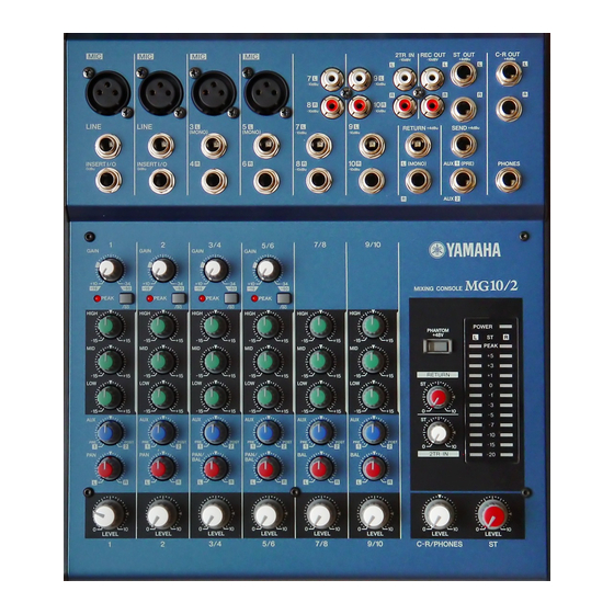
Page 8: Panel Layout
MG10/2 PANEL LAYOUT Channel Control Section Channels Channels Channels 1 and 2 3/4 and 5/6 7/8 and 9/10 (Monaural) (Stereo) (Stereo) [GAIN] Control [PEAK] Indicator [ 80 ] Switch (High Pass Filter) Equalizer ([HIGH], [MID], and [LOW]) [AUX] Controls [PAN] Control (CHs 1 and 2) - Page 9 MG10/2 Input/Output Section Channel Input Jacks (CHs 1, 2, 3/4, 5/6) [INSERT I/O] Jacks (CHs 1, 2) Channel Input Jacks (CHs 7/8, 9/10) [2TR IN] Jacks [REC OUT] (L, R) Jacks [ST OUT] (L, R) Jacks [C-R OUT] Jacks [SEND] Jacks...
- Page 10 MG10/2 Connector Polarities INPUT OUTPUT Pin 1: Ground MIC INPUT Pin 2: Hot (+) Pin 3: Cold (–) LINE INPUT (monaural channels), Tip: Hot (+) ST OUT, C-R OUT, Ring: Cold (–) AUX1, AUX2* Sleeve: Ground Ring Tip: Output INSERT I/O...
-
Page 11: Circuit Board Layout & Wiring
MG10/2 CIRCUIT BOARD LAYOUT & WIRING Rear view Right side view Top view MAIN Power switch and AC connector wiring (V975620) (Connector assembly 2P BROWN, RED) Wiring to MAIN circuit board Need twist of one rotation. Cable Colors Need twist of one rotation. -
Page 12: Disassembly Procedure
MG10/2 DISASSEMBLY PROCEDURE Bottom Case (Time required: About 1 minute) Remove the five (5) screws marked [250] and the two (2) screws marked [260]. The bottom case can then be removed. (Fig. 1) Rear view [270] [260] [260] MAIN Top view... - Page 13 MG10/2 AC Support (Time required: About 2 minutes) Remove the bottom case. (See procedure 1.) Remove the screw marked [270]. The AC support can then be removed. (Fig. 1, Photo. 1) MAIN Circuit Board (Time required: About 8 minutes) Remove the bottom case. (See procedure 1.) Remove the AC support.
-
Page 14: Ic Block Diagram
MG10/2 IC BLOCK DIAGRAM NJM4580ED (XT157A00) NJM4556AL (XP844A00) NJM2068MD-T1 (XJ553A00) MAIN: IC202, 302, 303, 402, 403, 501, 502, MAIN: IC101, 201, 301, 401, 801, 804 MAIN: IC806 601, 602, 701, 702, 802 Dual Operational Amplifier Dual Operational Amplifier NJM4558M (T1) (IG103520) -
Page 15: Circuit Board
MG10/2 CIRCUIT BOARD MAIN Circuit Board ST OUT C-R OUT 10 R AUX1 LINE (MONO) (MONO) (MONO) (PRE) PHONES 10 R AUX2 INSERT I/O RETURN SEND GAIN PEAK PEAK PEAK PEAK PHANTOM POWER +48V HIGH PEAK RETURN 2TR IN PAN/BAL... - Page 16 MG10/2 MAIN Circuit Board Pattern side...
- Page 17 MG10/2 INSPECTIONS Scope This inspection specification is applied to the mixer MG10/2. Power Supply AC Adaptor shall be used. V981040(H:230V 50Hz) or V981030(U:120V 60Hz), V981220(B:230V 50Hz), V981680(K:220V 60Hz), V986200(A:240V 50Hz) Power Indicator Inspection POWER LED shall light when the unit is turned on.
- Page 18 MG10/2 Table 4.2.2 [dBu] INSERT OUT INPUT INPUT Level Gain REC OUT L REC OUT R 1-4/8 -12 ± 2 Mic 1, 2 – – CH INSERT IN 1 Unspecified – +4.2± 2 +4.2± 2 CH INSERT IN 2 Unspecified –...
- Page 19 MG10/2 4.5 Channel Equalizer Characteristics In the state checked in 4.2 above, check the output level obtained at ST L OUT in the case of CH INPUT and ST CH INPUT L and at ST R OUT in the case of ST CH INPUT R when LO, HI and MID of INPUT are moved respectively.
- Page 20 MG10/2 4.10 Maximum Output In the state 4.9, the distortion factor shall be less than 1% when the output level is +20dBu at ST L OUT, ST R OUT, AUX1 OUT, AUX2 OUT and C-R OUT. The distortion factor shall be less than 1% when the output level is +7.5dBu at PHONES (L/R).
- Page 21 MG10/2 INPUT INPUT Gain ST L OUT ST R OUT AUX1 AUX2 C-R OUT L C-R OUT R Level 0 ± 2 *1 0 ± 2 *1 -1 ± 2 +5 ± 2 *2 +16 ± 2 *1 +16 ± 2 *1 +1 ±...
- Page 22 MG10/2 INSERT OUT INPUT INPUT Level Gain REC OUT L REC OUT R 1-4/8 -12 ± 2 Mic 1, 2 – – CH INSERT IN 1 Unspecified – +4.2± 2 +4.2± 2 CH INSERT IN 2 Unspecified – +4.2± 2 –...
- Page 23 MG10/2 EQ control EQ GAIN Applied frequency Variation width +12±2 10kHz -12±2 +15±2 2.5kHz -15±2 +12±2 100Hz -12±2 INPUT PEAK LED -43±2...
- Page 24 MG10/2 STEREO OUT AUX OUT C-R OUT -81.0 -85.0 -87.0 – -100.0 -93.0...
-
Page 25: Mixing Console
MIXING CONSOLE PARTS LIST CONTENTS OVERALL ASSEMBLY ..........2 ELECTRICAL PARTS ........4-17 Notes : DESTINATION ABBREVIATIONS A : Australian model M : South African model B : British model O : Chinese model C : Canadian model Q : South-east Asia model D : German model T : Taiwan model E : European model... - Page 26 MG10/2 OVERALL ASSEMBLY Meter reflector...
- Page 27 MG10/2 PART NO. DESCRIPTION REMARKS REF NO. RANK OVERALL ASSEMBLY MG10/2 (V981930) V 9 7 3 7 3 0 0 Circuit Board MAIN WA595400 Connector 3P SCMI405MOS3N000 AC ADAPTOR IN V 2 4 2 2 4 0 0 Power Switch...
- Page 28 MG10/2 ELECTRICAL PARTS PART NO. DESCRIPTION REMARKS REF NO. RANK ELECTRICAL PARTS MG10/2 V 9 7 3 7 3 0 0 Circuit Board MAIN (X3234B0) V 9 7 3 7 3 0 0 Circuit Board MAIN (X3234B0) Heat Sink (WA03810)
- Page 29 MG10/2 PART NO. DESCRIPTION REMARKS REF NO. RANK C211 V 9 7 2 1 5 0 0 Ceramic Capacitor (chip) 100P 50V K 0603 C212 V 9 7 2 0 9 0 0 Ceramic Capacitor (chip) 33P 50V K 0603...
- Page 30 MG10/2 PART NO. DESCRIPTION REMARKS REF NO. RANK C347 VV062400 Mylar Capacitor 0.047 50V J C348 V 9 7 2 1 5 0 0 Ceramic Capacitor (chip) 100P 50V K 0603 C349 V 9 7 2 1 5 0 0...
- Page 31 MG10/2 PART NO. DESCRIPTION REMARKS REF NO. RANK C503 V 9 7 2 1 5 0 0 Ceramic Capacitor (chip) 100P 50V K 0603 -506 V 9 7 2 1 5 0 0 Ceramic Capacitor (chip) 100P 50V K 0603...
- Page 32 MG10/2 PART NO. DESCRIPTION REMARKS REF NO. RANK C705 V 9 7 2 1 5 0 0 Ceramic Capacitor (chip) 100P 50V K 0603 -708 V 9 7 2 1 5 0 0 Ceramic Capacitor (chip) 100P 50V K 0603...
- Page 33 MG10/2 PART NO. DESCRIPTION REMARKS REF NO. RANK VN771700 Diode D1NS4 V 9 9 2 1 6 0 0 Diode 1N4004 D301 VT332900 Diode 1SS355 TE-17 -303 VT332900 Diode 1SS355 TE-17 D401 VT332900 Diode 1SS355 TE-17 -403 VT332900 Diode 1SS355 TE-17...
- Page 34 MG10/2 PART NO. DESCRIPTION REMARKS REF NO. RANK LD301 V 9 7 9 0 4 0 0 LED Red HFR203PJ-3-00 PEAK 3/4 LD401 V 9 7 9 0 4 0 0 LED Red HFR203PJ-3-00 PEAK 5/6 LD801 V 9 7 9 0 6 0 0...
- Page 35 MG10/2 PART NO. DESCRIPTION REMARKS REF NO. RANK R110 V 9 7 0 9 9 0 0 Carbon Resistor (chip) 10 0.1 J R111 V 9 7 1 9 3 0 0 Metal Film Resistor (chip) 47K 1/16 D R112...
- Page 36 MG10/2 PART NO. DESCRIPTION REMARKS REF NO. RANK R220 V 9 7 1 8 1 0 0 Metal Film Resistor (chip) 3.9K 1/16 D R221 V 9 7 1 9 0 0 0 Metal Film Resistor (chip) 33K 1/16 D...
- Page 37 MG10/2 PART NO. DESCRIPTION REMARKS REF NO. RANK R334 V 9 7 1 6 6 0 0 Carbon Resistor (chip) 220K 0.1 J R335 V 9 7 1 4 0 0 0 Carbon Resistor (chip) 10K 0.1 J R336 V 9 7 1 1 9 0 0 Carbon Resistor (chip) 680 0.1 J...
- Page 38 MG10/2 PART NO. DESCRIPTION REMARKS REF NO. RANK R432 V 9 7 0 9 9 0 0 Carbon Resistor (chip) 10 0.1 J R433 V 9 7 1 6 6 0 0 Carbon Resistor (chip) 220K 0.1 J R434 V 9 7 1 6 6 0 0 Carbon Resistor (chip) 220K 0.1 J...
- Page 39 MG10/2 PART NO. DESCRIPTION REMARKS REF NO. RANK R529 V 9 7 1 1 3 0 0 Carbon Resistor (chip) 220 0.1 J R530 V 9 7 1 1 3 0 0 Carbon Resistor (chip) 220 0.1 J R531 V 9 7 1 4 6 0 0 Carbon Resistor (chip) 18K 0.1 J...
- Page 40 MG10/2 PART NO. DESCRIPTION REMARKS REF NO. RANK R717 V 9 7 1 3 8 0 0 Carbon Resistor (chip) 8.2K 0.1 J R718 V 9 7 1 5 3 0 0 Carbon Resistor (chip) 36K 0.1 J R719 V 9 7 1 4 7 0 0 Carbon Resistor (chip) 20K 0.1 J...
- Page 41 MG10/2 PART NO. DESCRIPTION REMARKS REF NO. RANK -882 V 9 7 3 3 2 0 0 Carbon Resistor 1.5K 1/8 J R883 VV058500 Flame Proof C. Resistor 10.0 1/4 J R884 VV058500 Flame Proof C. Resistor 10.0 1/4 J...
-
Page 42: Circuit Diagram
MIXING CONSOLE CIRCUIT DIAGRAM CONTENTS BLOCK DIAGRAM ........3 OVERALL CIRCUIT DIAGRAM MAIN ................4-7 Notation for Circuit Diagrams 1. How to identify inter-sheet connectors to page 6: K8 The page number indicates the destination page. Signal name This indicates the location of the counter inter-sheet connector. (The alphabet indicates horizontal direction and the number indicates vertical direction) Note: See parts list for details of circuit board component parts. - Page 43 BLOCK DIAGRAM & LEVEL DIAGRAM MG10/2 SW102 MAIN +48V JK101, 201 LD102 PHANTOM [-60dBu~-16dBu] IC101, 201 (8P) IC802a (8P) IC804a (8P) VR801 SW101, 201 IC103 (8P) JK802 LD101, 201 CH IN VR107, 207 VR105, 205 PEAK CH1-2 JK102, 202 IC202 (8P)
- Page 44 OVERALL CIRCUIT DIAGRAM 1/4 (MAIN) MG10/2 PHANTOM+48V MAIN to Page 6: K8 LEVEL to Page 6: J8 GAIN OP AMP to Page 6: H8 OP AMP OP AMP to Page 6: I8 MONO CH1 HIGH OP AMP LINE PEAK INSERT I/O...
- Page 45 OVERALL CIRCUIT DIAGRAM 2/4 (MAIN) MG10/2 MAIN HIGH to Page 6: K8 OP AMP to Page 6: J8 ST CH OP AMP OP AMP CH7 (L)/CH8 (R) to Page 6: H8 OP AMP to Page 6: I8 OP AMP OP AMP...
- Page 46 OVERALL CIRCUIT DIAGRAM 3/4 (MAIN) MG10/2 MAIN LED DRIVER OP AMP OP AMP OP AMP OP AMP LED DRIVER OP AMP OP AMP OP AMP OP AMP : Ceramic Capacitor from Page 4: A1, from Page 4: A1, from Page 4: A2,...
- Page 47 OVERALL CIRCUIT DIAGRAM 4/4 (MAIN) MG10/2 MAIN REGULATOR +15V ON/STANDBY (POWER) REGULATOR -15V AC ADAPTOR REGULATOR +12V NJM7915FA(XD854A00) NJM7815FA(XD853A00) REGULATOR -15V REGULATOR +15V REGULATOR +5V 1: OUTPUT 1: OUTPUT 2: INPUT 2: COMMON 3: COMMON 3: INPUT NJM7812FA(XJ608A00) NJM7805FA(XJ607A00) REGULATOR +12V...
Need help?
Do you have a question about the MG10/2 and is the answer not in the manual?
Questions and answers