Yamaha MG10/2 Service Manual
Hide thumbs
Also See for MG10/2:
- Owner's manual (28 pages) ,
- Service manual (48 pages) ,
- Service manual (47 pages)
Table of Contents
Advertisement
A manufacture number should use this
manual with goods of 9 or more figures.
(本マニュアルは、製造番号が9桁以上の商
品でご使用ください。)
The example of a manufacture number.
(製造番号例)
JCLJ01001
UCCLJ01001
CHNCL01001
9-11 figures
(9~11桁)
The service manual of PA 011679 should
be used for the goods whose manufacture
number is 7 figures.
(製造番号が7桁の商品は、PA 011679 の
サービスマニュアルをご使用ください。)
The example of a manufacture number.
(製造番号例)
LK01001
7 figures
(7桁)
011780
PA
200306-14800
MIXING CONSOLE
SERVICE MANUAL
SPECIFICATIONS (総合仕様) ............................................... 3/5
DIMENSIONS (寸法図)........................................................... 7
PANEL LAYOUT (パネルレイアウト) ...................................... 8
(ユニットレイアウト&結線図) .............................................. 11
DISASSEMBLY PROCEDURE (分解手順) ............................. 12
IC BLOCK DIAGRAM (IC ブロック図) .................................. 14
CIRCUIT BOARD (シート基板図) .......................................... 15
INSPECTIONS (検査) ....................................................... 17/21
(ブロックダイアグラム&レベルダイアグラム)
Copyright (c) Yamaha Corporation. All rights reserved. PDF-K344
HAMAMATSU, JAPAN
HAMAMATSU, JAPAN
'05.08
Advertisement
Table of Contents

Related Manuals for Yamaha MG10/2


Summary of Contents for Yamaha MG10/2
-
Page 1: Table Of Contents
The example of a manufacture number. INSPECTIONS (検査) ............17/21 (製造番号例) PARTS LIST LK01001 BLOCK DIAGRAM & LEVEL DIAGRAM (ブロックダイアグラム&レベルダイアグラム) 7 figures OVERALL CIRCUIT DIAGRAM (総回路図) (7桁) 011780 HAMAMATSU, JAPAN HAMAMATSU, JAPAN 200306-14800 Copyright (c) Yamaha Corporation. All rights reserved. PDF-K344 ’05.08... - Page 2 IMPOR TANT NOTICE This manual has been provided for the use of authorized Yamaha Retailers and their service personnel. It has been assumed that basic service procedures inherent to the industry, and more specifically Yamaha Products, are already known and under- stood by the users, and have therefore not been restated.
-
Page 3: I Contents (目次) Specifications (総合仕様
MG10/2 SPECIFICATIONS General Specifications Frequency Characteristics (ST OUT) 20 Hz-20 kHz +1 dB, -3 dB @+4 dBu, 10 kΩ (with gain control at maximum level) 0.1 % (THD+N) @+14 dBu, 20 Hz-20 kHz, 10 kΩ (with gain control at maximum level) - Page 4 MG10/2 Input Specifications Input Appropriate Max. Before Connector Input Connector Gain Sensitivity* Rated Level Impedance Impedance Clipping Specifications –72 dBu –60 dBu –40 dBu –60 (0.195 mV) (0.775 mV) (7.75 mV) MIC INPUT Ω Ω 50–600 XLR-3-31 type (balanced) (CH 1-2) –28 dBu...
- Page 5 MG10/2 総合仕様 一般仕様 周波数特性 (ST OUT) 20 Hz∼20 kHz +1 dB、-3 dB @+4 dBu (*) 、10 kΩ (GAIN コントロール=最大レベル) 0.1 % (THD+N) @+14 dBu, 20 Hz∼20 kHz 、10 kΩ (GAIN コントロール=最大レベル) 全高調波歪率 (ST OUT) (CH1 、2) -128 dBu 入力換算ノイズ (CH1、2) -100 dBu 残留ノイズ...
- Page 6 MG10/2 入力仕様 入力イン 最大ノンク 入力端子名称 ゲイン 適合インピーダンス 規定レベル 端子仕様 感度 ピーダンス リップレベル MIC INPUT 50 ∼ 600 Ω マイク –72 dBu –60 dBu –40 dBu 3 k Ω –60 (CH1-2 ) ( 0.195 mV ) ( 0.775 mV ) ( 7.75 mV )...
-
Page 7: Dimensions (寸法図
MG10/2 DIMENSIONS (寸法図) Units: mm (単位)... -
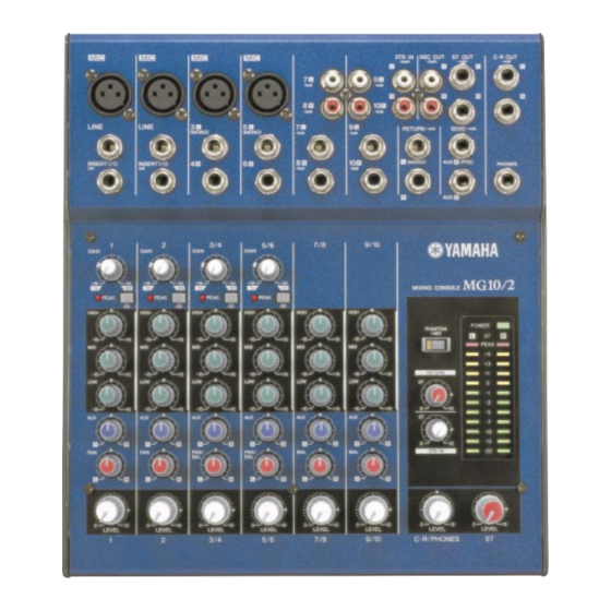
Page 8: Panel Layout (パネルレイアウト
MG10/2 I PANEL LAYOUT (パネルレイアウト) Channel Control Section (チャンネルコントロール部) ● Channels Channels Channels 1 and 2 3/4 and 5/6 7/8 and 9/10 (Monaural) (Stereo) (Stereo) [GAIN] Control [PEAK] Indicator [ 80 ] Switch (High Pass Filter) Equalizer ([HIGH], [MID], and [LOW]) - Page 9 MG10/2 Input/Output Section (入出力部) ● チャンネル INPUT 端子(CH 1、 2、 3/4、 5/6) Channel Input Jacks (CHs 1, 2, 3/4, 5/6) [INSERT I/O] 端子(CH 1、 2) [INSERT I/O] Jacks (CHs 1, 2) Channel Input Jacks (CHs 7/8, 9/10) チャンネル INPUT 端子(CH 7/8、 9/10)...
- Page 10 MG10/2 Connector Polarities INPUT OUTPUT Pin 1: Ground MIC INPUT Pin 2: Hot (+) Pin 3: Cold (–) LINE INPUT (monaural channels), Tip: Hot (+) ST OUT, C-R OUT, Ring: Cold (–) AUX1, AUX2* Sleeve: Ground Ring Tip: Output INSERT I/O...
-
Page 11: Circuit Board Layout & Wiring (ユニットレイアウト&結線図
MG10/2 CIRCUIT BOARD LAYOUT & WIRING (ユニットレイアウト & 結線図) • Rear view • Right side view • Top view MAIN Power switch and AC connector wiring (電源スイッチとACコネクタの結線) WB071100 (Shrink Tube Black : 7 places) (熱収縮チューブ:7箇所) WA595401 (Connector 3P BROWN, RED, BLACK) Top Cover (a). -
Page 12: Disassembly Procedure (分解手順
MG10/2 DISASSEMBLY PROCEDURE (分解手順) ボトムケース (所要時間:約1 分) Bottom Case (Time required: About 1 minute) Remove the five (5) screws marked [250] and the [250] のネジ5 本と[260] のネジ2 本を外し、ボトム two (2) screws marked [260]. The bottom case can ケースを外します。 (図1 )... - Page 13 MG10/2 サポートAC (所要時間:約2 分) AC Support (Time required: About 2 minutes) Remove the bottom case. (See procedure 1.) ボトムケースを外します。 (1 項参照) Remove the screw marked [270]. The AC support [270] のネジ1 本を外し、サポートAC を外します。 can then be removed. (Fig. 1, Photo. 1) (図1 、写真1)...
-
Page 14: Ic Block Diagram (Ic ブロック図
MG10/2 IC BLOCK DIAGRAM (IC ブロック図) NJM4556AL (XP844A00) NJM2068M-D (TE2) (X3505A00) NJM4580ED (XT157A00) MAIN: IC202, 302, 303, 402, 403, 501, 502, MAIN: IC101, 201, 301, 401, 801, 804 MAIN: IC806 601, 602, 701, 702, 802 Dual Operational Amplifier Dual Operational Amplifier... -
Page 15: Circuit Board (シート基板図
MG10/2 CIRCUIT BOARD (シート基板図) • MAIN Circuit Board ST OUT C-R OUT 10 R AUX1 LINE (MONO) (MONO) (MONO) (PRE) PHONES 10 R AUX2 INSERT I/O RETURN SEND GAIN PEAK PEAK PEAK PEAK PHANTOM POWER +48V HIGH PEAK RETURN 2TR IN... - Page 16 MG10/2 • MAIN Circuit Board Pattern side (パターン側) 2NA-WE52140...
-
Page 17: Inspections (検査
MG10/2 INSPECTIONS Measurement conditions 1-1. Environment Normal temperature (10 to 35C) Normal humidity (45 to 85%) 1-2. Power Source The voltage is within +/-10%. AC Adaptor (PA-10) shall be used. WC703600 (H,W:230V) or WC703500 (U,V:120V), WC703700 (B:230V), WC703800 (K:220V), WC703900 (A:240V),... - Page 18 MG10/2 2-6. Gain The output levels shall be within the range specified in the Table 2.6.1 to 2.6.6. Table 2.6.1 CH INPUT(1, 2) [dBu] INPUT INPUT Gain ST L OUT ST R OUT AUX1 AUX2 C-R OUT L C-R OUT R...
- Page 19 MG10/2 2-8. HPF In the state of the Table 2.6.1 and 2.6.2, feeding 80 Hz -36dBu signal, and setting the GAIN to MIN, the STEREO L OUT level obtained when the 80 switch is set to ON shall be within the range of -3dB +/-2dB compared to the level obtained when the switch is set to OFF.
- Page 20 MG10/2 2-14. Maximum Output In the state 2-2., the distortion factor shall be less than 1% when the output level is +20dBu at ST L OUT, ST R OUT, AUX1 OUT, AUX2 OUT and C-R OUT. The distortion factor shall be less than 1% when the output level is +7.5dBu at PHONES (L/R).
- Page 21 MG10/2 検査 測定条件 1-1. 環境 常温 (10∼35℃) 常湿 (45∼85%) 1-2. 電源電圧 電源電圧の ±10%以内 AC アダプター (PA-10) を使用します。 WC703400 ( J:100V) 電気的特性 2-1. 準備 各出力端子の負荷抵抗は下記の通りです。 ・PHONES (L, R): 40 Ω ・その他出力: 10 kΩ 2-2. 特に指定の無い場合、ツマミ類は以下のように設定してください。 ・CH (1-2) INPUT GAIN control MAX (-60dBu)...
- Page 22 MG10/2 2-6. 利得 2-2. の状態で各出力端子には [表2.6.1∼2.6.6] の範囲内の出力レベルが得られることを確認します。 表 2.6.1 CH INPUT(1, 2) [dBu] INPUT INPUT Gain ST L OUT ST R OUT AUX1 AUX2 C-R OUT L C-R OUT R Level 0 +/-2 *1 0 +/-2 *1 -1 +/-2 +5 +/-2 *2...
- Page 23 MG10/2 2-8. HPF 表2.6.1 、表2.6.2 の状態で入力レベル -36dBu 、Gain をMIN として入力信号を80Hz とし、 80 switch をON にしたとき、 STEREO L OUT の出力レベルはOFF 時のレベルを基準として -3 ±2dB の範囲内であることを確認します。 2-9. チャンネルEQ 変化特性 2-2. の状態で、INPUT のLO, MID, HI をそれぞれ動かした時、CH INPUT 及びST CH INPUT L はST L OUT で、ST CH INPUT R はST R OUT で得られる各周波数における出力レベルは、EQ gain control センタークリック位置の出力レベル...
- Page 24 MG10/2 2-14. 最大出力 2-2. の状態でST L OUT, ST R OUT, AUX1 OUT, AUX2 OUT, C-R OUT に+20dBu 歪率1% 以下の出力が得られることを確認 します。 PHONES (L, R) に+7.5dBu 歪率1% 以下の出力が得られることを確認します。 ST L OUT, ST R OUT 測定時は、PAN またはPAN/BAL, BAL control をそれぞれL, R に回しきってください。 C-R OUT, PHONE 測定時は、C-R/PHONE control をMAX にしてください。...
-
Page 25: Parts List
MIXING CONSOLE PARTS LIST (目次) CONTENTS (総組立) OVERALL ASSEMBLY ..........2 (電気部品) ELECTRICAL PARTS ........4-18 Notes : DESTINATION ABBREVIATIONS A : Australian model M : South African model B : British model O : Chinese model C : Canadian model Q : South-east Asia model D : German model T : Taiwan model... - Page 26 MG10/2 I OVERALL ASSEMBLY (総組立) Hexagon nut & Washer are Accessories of Phone Jack. (六角ナットとワッシャーは、ホーンジャックの付属品です。) Reflector meter (リフレクターMETER)...
- Page 27 MG10/2 PART NO. DESCRIPTION 部 品 名 REMARKS REF NO. QTY RANK OVERALL ASSEMBLY 総 組 立 MG10/2 (WE71530) WE521400 Circuit Board MAIN シ ー ト M A I N VA126400 Filament Tape 12x50 粘 着 テ ー プ WE718500 Top Cover ト...
- Page 28 MG10/2 I ELECTRICAL PARTS (電気部品) PART NO. DESCRIPTION 部 品 名 REMARKS REF NO. QTY RANK ELECTRICAL PARTS 電 気 部 品 MG10/2 WE521400 Circuit Board MAIN シ ー ト M A I N (X6347B0) WE521400 Circuit Board MAIN シ ー ト M A I N...
- Page 29 MG10/2 PART NO. DESCRIPTION 部 品 名 REMARKS REF NO. QTY RANK C210 US061330 Ceramic Capacitor-CH(chip) 33P 50V J チ ッ プ セ ラ ( C H ) C211 US062100 Ceramic Capacitor-SL(chip) 100P 50V J チ ッ プ セ ラ ( S L )...
- Page 30 MG10/2 PART NO. DESCRIPTION 部 品 名 REMARKS REF NO. QTY RANK C346 V9726500 Electrolytic Cap. ケ ミ コ ン C347 UA654470 Mylar Capacitor 0.047 50V J マ イ ラ ー コ ン C348 US062100 Ceramic Capacitor-SL(chip) 100P 50V J チ...
- Page 31 MG10/2 PART NO. DESCRIPTION 部 品 名 REMARKS REF NO. QTY RANK C502 V9726500 Electrolytic Cap. ケ ミ コ ン C503 US062100 Ceramic Capacitor-SL(chip) 100P 50V J チ ッ プ セ ラ ( S L ) -506 US062100 Ceramic Capacitor-SL(chip) 100P 50V J チ...
- Page 32 MG10/2 PART NO. DESCRIPTION 部 品 名 REMARKS REF NO. QTY RANK -704 V9726500 Electrolytic Cap. ケ ミ コ ン C705 US062100 Ceramic Capacitor-SL(chip) 100P 50V J チ ッ プ セ ラ ( S L ) -708 US062100 Ceramic Capacitor-SL(chip) 100P 50V J チ...
- Page 33 MG10/2 PART NO. DESCRIPTION 部 品 名 REMARKS REF NO. QTY RANK VN771700 Diode D1NS4 ダ イ オ ー ド VN771700 Diode D1NS4 ダ イ オ ー ド WD543900 Diode 1N4004 DO-41 ダ イ オ ー ド D301 VT332900 Diode 1SS355 TE-17 ダ...
- Page 34 MG10/2 PART NO. DESCRIPTION 部 品 名 REMARKS REF NO. QTY RANK LD201 V9790400 LED Red HFR203PJ-3-00 L E D PEAK 2 LD301 V9790400 LED Red HFR203PJ-3-00 L E D PEAK 3/4 LD401 V9790400 LED Red HFR203PJ-3-00 L E D...
- Page 35 MG10/2 PART NO. DESCRIPTION 部 品 名 REMARKS REF NO. } QTY RANK Q801 WC529400 Transistor KTC3875S-Y,GR-RTK/ ト ラ ン ジ ス タ Q802 VV556500 Transistor 2SA1037AK Q,R,S ト ラ ン ジ ス タ } Q802 WC529500 Transistor KTA1504S-Y,GR-RTK/ ト...
- Page 36 MG10/2 PART NO. DESCRIPTION 部 品 名 REMARKS REF NO. QTY RANK R162 HV755100 Flame Proof C.Resistor 100 1/4W J 不 燃 化 カ ー ボ ン 抵 抗 R163 HF456270 Carbon Resistor 2.7K 1/4W J カ ー ボ ン...
- Page 37 MG10/2 PART NO. DESCRIPTION 部 品 名 REMARKS REF NO. QTY RANK R313 RF355360 Carbon Resistor (chip) 360 1/16W D チ ッ プ 抵 抗 R314 RD356220 Carbon Resistor (chip) 2.2K 1/16W J チ ッ プ 抵 抗 R315 RD356220 Carbon Resistor (chip) 2.2K 1/16W J...
- Page 38 MG10/2 PART NO. DESCRIPTION 部 品 名 REMARKS REF NO. QTY RANK R410 RF356220 Carbon Resistor (chip) 2.2K 1/16W D チ ッ プ 抵 抗 R411 RF356390 Carbon Resistor (chip) 3.9K 1/16W D チ ッ プ 抵 抗 R413 RF355360...
- Page 39 MG10/2 PART NO. DESCRIPTION 部 品 名 REMARKS REF NO. QTY RANK R508 RD355220 Carbon Resistor (chip) 220 1/16W J チ ッ プ 抵 抗 R509 RD356820 Carbon Resistor (chip) 8.2K 1/16W J チ ッ プ 抵 抗 R510 RD356820 Carbon Resistor (chip) 8.2K 1/16W J...
- Page 40 MG10/2 PART NO. DESCRIPTION 部 品 名 REMARKS REF NO. QTY RANK R634 RD355220 Carbon Resistor (chip) 220 1/16W J チ ッ プ 抵 抗 R635 RD357180 Carbon Resistor (chip) 18K 1/16W J チ ッ プ 抵 抗 -638 RD357180...
- Page 41 MG10/2 PART NO. DESCRIPTION 部 品 名 REMARKS REF NO. QTY RANK R852 HF455220 Carbon Resistor 220 1/4W J カ ー ボ ン 抵 抗 -855 HF455220 Carbon Resistor 220 1/4W J カ ー ボ ン 抵 抗 R856 RD354750...
- Page 42 MG10/2 PART NO. DESCRIPTION 部 品 名 REMARKS REF NO. QTY RANK VR701 V8265100 Rotary Variable Resistor A 20K XV012313 2 連 ロ ー タ リ ー V R 2TR IN ST VR702 V8265100 Rotary Variable Resistor A 20K XV012313 2...
-
Page 43: Block Diagram & Level Diagram
MIXING CONSOLE CIRCUIT DIAGRAM (目次) CONTENTS & LEVEL DIAGRAM BLOCK DIAGRAM (ブロック図&レベルダイアグラム) ........3 (総回路図) OVERALL CIRCUIT DIAGRAM MAIN ................4-7 Notation for Circuit Diagrams (回路図表記上の注意) 1. How to identify inter-sheet connectors (シート間コネクタの読み方について) to page 6: K8 The page number indicates the destination page. Signal name (ページNo.は信号の行先ページを示します。)... - Page 44 BLOCK DIAGRAM & LEVEL DIAGRAM MG10/2 MAIN SW102 +48V JK101, 201 LD102 PHANTOM [-60dBu~-16dBu] IC101, 201 (8P) IC802a (8P) IC804a (8P) VR801 SW101, 201 IC103 (8P) JK802 LD101, 201 CH IN VR107, 207 VR105, 205 PEAK CH1-2 JK102, 202 ST Mater...
- Page 45 OVERALL CIRCUIT DIAGRAM 1/4 (MAIN) MG10/2 PHANTOM+48V to Page 6: K8 MAIN LEVEL to Page 6: J8 GAIN OP AMP to Page 6: H8 OP AMP OP AMP to Page 6: I8 MONO CH1 HIGH LINE OP AMP PEAK INSERT I/O...
- Page 46 OVERALL CIRCUIT DIAGRAM 2/4 (MAIN) MG10/2 MAIN HIGH to Page 6: K8 OP AMP OP AMP ST CH to Page 6: J8 OP AMP CH7 (L)/CH8 (R) to Page 6: H8 to Page 6: I8 OP AMP OP AMP OP AMP...
- Page 47 OVERALL CIRCUIT DIAGRAM 3/4 (MAIN) MG10/2 MAIN LED DRIVER OP AMP OP AMP OP AMP OP AMP LED DRIVER OP AMP OP AMP OP AMP OP AMP ( セ ) : Ceramic Capacitor (セラミックコンデンサー) from Page 4: A1 from Page 4: A1...
- Page 48 OVERALL CIRCUIT DIAGRAM 4/4 (MAIN) MG10/2 MAIN REGULATOR +15V 1A 250V X 2 ON/STANDBY (POWER) REGULATOR -15V AC ADAPTOR REGULATOR +12V KIA7915PI(X4931A00) KIA7815API(X4930A00) REGULATOR -15V REGULATOR +15V IC01 IC02 REGULATOR +5V 1: COMMON 1: INPUT 2: INPUT 2: GND 3: OUTPUT...