Table of Contents
Advertisement
Quick Links
4012/16 Diesel
1
General information
1
Introduction
The 4012 and 4016 diesel engines are a family of 12 and 16 cylinder turbocharged diesel engines, designed
by Perkins Engines Company Limited, Stafford, a world leader in the design and manufacture of high-
performance diesel engines. They form part of the 4000 Series range of engines.
Perkins approved assembly and quality standards, together with the latest technology, have been applied to
the manufacture of your engine to give you reliable and economic power.
Read and remember the
"Safety precautions" on page
2. They are given for your protection and must be
observed at all times.
To ensure that you use the correct information for your specific engine type, refer to
page
11.
Note: The terms 'left side' and 'right side' apply when the engine is viewed from the flywheel end.
Special tools are required to perform certain operations. A list of those required for the operations described
in this handbook is given in
"Service tools" on page
9. Reference to the relevant special tools is also made at
the beginning of each operation, along with those which are universally available (UA) and any additional
specialist supplied equipment (SP) required.
Danger is indicated in the text by two methods:
Warning! This indicates that there is a possible danger to the person.
Caution: This indicates that there is a possible danger to the engine.
Note: Is used where the information is important, but there is not a danger.
User's Handbook, TSL 4186E, Issue 2
1
Advertisement
Table of Contents

Related Manuals for Perkins 4012


Summary of Contents for Perkins 4012
-
Page 1: General Information
General information Introduction The 4012 and 4016 diesel engines are a family of 12 and 16 cylinder turbocharged diesel engines, designed by Perkins Engines Company Limited, Stafford, a world leader in the design and manufacture of high- performance diesel engines. They form part of the 4000 Series range of engines. -
Page 2: Safety Precautions
4012/16 Diesel Safety precautions General For safe and reliable operation of the engine it is very important that these safety precautions, and those Warnings and Cautions given throughout this handbook, are observed, and where necessary the special tools indicated are used. - Page 3 4012/16 Diesel Start-up When working on the engine always ensure that the battery has been disconnected, and that any other means of accidental start-up has been disabled. Never start the engine with the governor linkage disconnected. Do not hold the stop lever in the run position when starting the engine.
- Page 4 4012/16 Diesel Flammable fluids Ensure that these are never stored near the engine. Ensure that they are never used near a naked light. Clothing Do not wear loose clothing, ties, jewellery, etc. Always wear steel toe cap shoes/boots. Always wear the correct head, eye and ear protection.
-
Page 5: How To Care For Your Engine
Company Limited, Stafford and subject to oil analysis being carried out at regular intervals. Ensure that all adjustments and repairs are done by personnel who have had the correct training. Perkins distributors have this type of personnel available. You can also obtain parts and service from your Perkins distributor. -
Page 6: Environmental Protection
4012/16 Diesel Dangers from used engine oils Prolonged and repeated contact with mineral oil will result in the removal of natural oils from the skin, leading to dryness, irritation and dermatitis. The oil also contains potentially harmful contaminants which may result in skin cancer. - Page 7 4012/16 Diesel Danger from ‘fluorosilicone’ (Viton) ‘O’ ring seals All of the engines ‘O’ ring seals are made from fluorosilicone material. It is a safe material under normal conditions of operation, but if it is burned the extremely dangerous hydroflouric acid is produced.
-
Page 8: Engine Preservation
Local training for the correct operation, service and overhaul of engines is available at certain Perkins distributors. If special training is necessary, your Perkins distributor can advise you how to obtain it at the Perkins Customer Training Department or other main centres. -
Page 9: Service Tools
4012/16 Diesel Service tools The tools and equipment which follow are required for the operations described in this handbook. Universally available tools Description Screwdriver (bridge piece and valve clearance adjustment) 17 mm Combination spanner (bridge piece adjuster locknut) 19 mm Combination spanner (rocker adjuster locknut) - Page 10 4012/16 Diesel Description of 4012 series engine models Reference Description Code 12 cylinder "V" form diesel engine, water cooled, turbocharged (twin turbochargers), jacket water 4012TWG cooled charge air coolers. Oil coolers in engine cooling circuit. Horizontal air cleaners. Uprated version of the 4012TWG. 12 cylinder "V" form diesel engine, water cooled, turbocharged (twin 4012TWG2 turbochargers), jacket water cooled charge air coolers.
-
Page 11: Engine Identification
On engines built from February 2000, the engine number is stamped on the face of the crankcase ‘B’ bank, above the gearcase (A3). For reference codes and engine description refer to "Description of 4012 series engine models" on page 10 "Description of 4016 series engine models" on page CGL0801... -
Page 12: Engine Specifications
4012/16 Diesel Engine specifications The figures quoted are based on engines set to meet the requirements of ISO 8528. For full technical data please refer to the appropriate Technical Data sheet. General engine data Engine model 4012 4016 Cycle 4 stroke 4 stroke No. -
Page 13: Induction System
4012/16 Diesel Cooling system Engine model 4012 4016 Approved coolants "Coolant specification" on page 60 Ltrs Gals Spec Ltrs Gals Spec 56.1 TAG1 TAG1 Total water capacity TAG2 TAG2 TWG2 TWG2 23.7 Maximum radiator top tank temperature 93 °C Maximum water temperature into engine 80 °C... -
Page 14: Lubrication System
4012/16 Diesel Lubrication system Engine model 4012 4016 Recommended oil "Lubricating oil recommendations" on page 58 Type of system Wet sump, external engine mounted oil pump Total oil capacity (including cooler and filter) 178 litres (39.2 gal) 238 litres (53 gal) -
Page 15: Electrical System
4012/16 Diesel Protection equipment Before resetting protection equipment, it must be established whether special settings (for that individual engine) have been specified in the engine sales contract. This is particularly important with ALL high water temperature settings, and ALL Cogen applications. - Page 16 4012/16 Diesel 4012/16 engine wiring diagram (twin starters, single start relay and electronic governor) Item Description Engine fitted terminal box Starter motor 1 Starter motor 2 Emergency stop Start inhibit relays Start relay Fuel stop solenoids (energised to run) Magnetic pick-ups...
- Page 17 4012/16 Diesel 4012 engine wiring diagram (twin starters and electronic governor) Item Description Item Description Engine fitted terminal box Overspeed Oil pressure switch 'A' bank engine fault switches Starter motor 1 'B' bank engine fault switches Starter motor 2 Water temperature...
- Page 18 4012/16 Diesel 4016 engine wiring diagram (twin starters and electronic governor) Item Description Item Description Engine fitted terminal box Overspeed Oil pressure switch Magnetic pick-ups Starter motor 1 Engine flywheel Starter motor 2 Electronic governor control box Battery charging alternator...
-
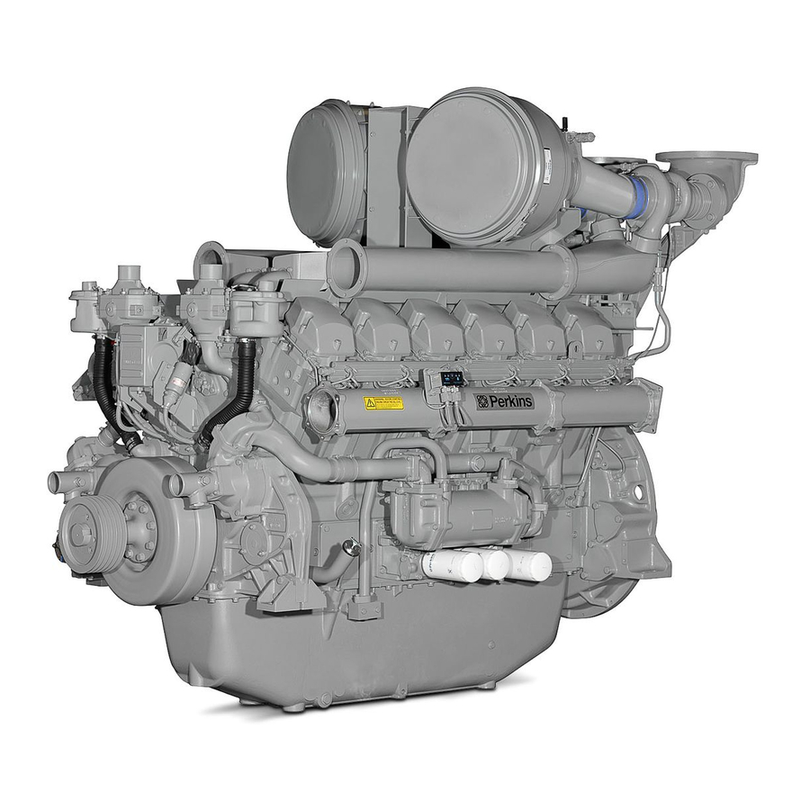
Page 19: Engine Views
4012/16 Diesel Engine views Introduction Perkins engines are built for specific applications and the views which follow do not necessarily match your engine specification. 12 cylinder engines ‘B’ Bank (gearcase end) ‘A’ Bank (flywheel end) User’s Handbook, TSL 4186E, Issue 2... - Page 20 4012/16 Diesel 16 cylinder engines ‘B’ Bank (gearcase end) ‘A’ Bank (flywheel end) User’s Handbook, TSL 4186E, Issue 2...
-
Page 21: Operating Instructions
Operating instructions Introduction Information for the mechanical maintenance of the 4012/16 diesel engines is given in this User’s Handbook (TSL 4186E) and the Workshop Manual (TSL 4165E). These publications should be understood and used together for the safe operation of the engine. - Page 22 4012/16 Diesel Engine instrumentation General description The standard instrument panel is normally supplied as a loose item, but can be fitted to ‘A’ bank air inlet manifold. The individual components of the instrument are shown in (A), and listed below:...
- Page 23 4012/16 Diesel Instrument operation Engine coolant temperature (A) 1 The temperature during normal operation should be between 65 °C - 85 °C (149 °F - 185 °F). 2 If the temperature should rise above 93 °C (200 °F) the engine protection switch will automatically stop the engine.
- Page 24 4012/16 Diesel Tachometer and hour counter (E) The electrically operated tachometer/hour counter shows the speed of the engine and the actual operating hours the engine has run. Three position keyswitch (F) The hand operated keyswitch with switch lock is moved by a separate key to the following positions:...
- Page 25 4012/16 Diesel How to fill the engine with oil 1 Remove the sump drain plug and check that the sump is clean and empty. Refit and tighten the plug. 2 Remove the oil filler plug situated on the side of the crankcase by rotating the T-bar (A1) anti-clockwise and pulling.
- Page 26 4012/16 Diesel How to prime the lubrication system Caution: Before starting the engine for the first time, or after it has stood idle for more than three months, the engine lubrication system must be primed. To achieve this the engine is cranked over on the starter motors using the following procedure.
- Page 27 4012/16 Diesel How to fill the engine and charge cooler cooling system (when fitted) Combined engine and charge cooler radiator systems are normally supplied for individual installations. A separate radiator may be used by an OEM. The engine operator must be aware of the filler cap position.
- Page 28 4012/16 Diesel How to prime the fuel system (4012 engines with standard filter/water separator) Caution: A small container or an absorbent material must be used to catch/soak up spilled fuel. 1 Loosen the fuel fitting nut (A1) on the fuel rail feed pipe, at the flywheel end of the fuel rail ‘A’ bank.
- Page 29 4012/16 Diesel How to prime the fuel system (4016 engines with standard filter) Caution: A small container or an absorbent material must be used to catch/soak up spilled fuel. 1 Loosen the fuel fitting nut (A1) on the fuel rail feed pipe, at the flywheel end of the fuel rail ‘A’ bank.
- Page 30 4012/16 Diesel How to prime the fuel system (4012/16 engines with optional change-over filters) Caution: A small container or an absorbent material must be used to catch/soak up spilled fuel. 1 Open the fuel vent screws (A1) on top of the change-over filters.
- Page 31 4012/16 Diesel Final checks and first engine start For the initial starting of a new or overhauled engine the following procedure should be followed. 1 Disengage the load. Check the air shut off valve is in the run position. 2 Turn the keyswitch to the start position. This will crank the engine over.
- Page 32 4012/16 Diesel Normal starting and shutdown procedure Normal starting 1 Turn the keyswitch to the start position. The engine should start immediately. 2 Release the keyswitch. 3 Check the instrument panel readings. 4 Run the engine for a minimum of 15 seconds before applying load.
-
Page 33: Preventive Maintenance
4012/16 Diesel Preventive maintenance Maintenance procedures These maintenance procedures are suitable for an engine working under average conditions. If your engine is working under particularly dirty or dusty conditions, more frequent servicing will be necessary particularly in respect of the lubricating oil and air cleaners. - Page 34 4012/16 Diesel Service schedule (prime and baseload rated engines) Note: The following service schedules have been developed for engines using the standard oil filtration system. The procedures indicated in the service schedule require reference to the following publications: User’s Handbook - TSL 4186E (UH)
- Page 35 4012/16 Diesel D Service - Every 7500 hours Description Manual Cylinder heads - change Injector unit - test and replace if faulty Fuel system - flush out Charge cooler (engine mounted) - remove and clean Charge cooler (radiator type) - clean radiator matrices...
- Page 36 Notes: Maintenance schedule from 30,000 hrs to 45,000 hrs is the same as 2,000 to 15,000 hrs. At 45,000 hrs operation consult Perkins Engines Company Limited, Stafford reference major overhaul and service exchange engine components. User’s Handbook, TSL 4186E, Issue 2...
- Page 37 4012/16 Diesel Service schedule (stand-by duty engines) The procedures indicated in the service schedule require reference to the following publications: User’s Handbook - TSL 4186E (UH) Workshop Manual - TSL 4165E (WM) This maintenance procedure is for engines used less than 400 hours in every 12 months.
- Page 38 4012/16 Diesel How to check the lubricating oil level 1 Stop the engine and wait 5 minutes to allow the oil to drain into the sump. 2 Withdraw the dipstick and wipe clean. 3 Insert the dipstick and wait 2 seconds.
- Page 39 4012/16 Diesel How to check and clean the radiator (if fitted) Special requirements Special tools Description Part number Description Part number Air compressor Steam cleaner Under normal operating conditions the radiator cooling fins should be inspected for a build up of dust and oil contamination every 3 months.
- Page 40 4012/16 Diesel How to check and adjust the radiator fan drive belts (if fitted) 1 Remove the mesh guard from around the fan belts. 2 Grease the fan bearings and jockey pulley bearings. 3 Check the tension and wear of the fan belts using hand pressure midway between the crankshaft and the pulley.
- Page 41 4012/16 Diesel How to check and adjust the battery charging alternator (if fitted) Caution: The toothed belt used to drive the alternator relies on tooth engagement to transmit the load. It does not require pre-loading. 1 To inspect the drive belt remove the guard (A1).
- Page 42 4012/16 Diesel How to change the engine oil and standard oil filter Draining the engine sump A container with the following capacity will be required: 12 cylinder engines - 159 litres (35 gal) 16 cylinder engines - 214 litres (47 gal) 1 Remove the sump drain plug and allow the oil to drain into the container.
- Page 43 4012/16 Diesel How to change the change-over filters (if fitted) With engine running 1 With both filters on line the marking on the change-over valve will be as (A1). 2 Using a spanner turn the change-over valve to position (A2) directing the oil away from the right hand filter.
- Page 44 4012/16 Diesel How to clean the centrifugal oil filter (if fitted) Special requirements Special tools Description Part number Rotor stand tube removal tool T6253/293 1 Stop the engine and wait for the rotor to stop spinning. 2 Slacken the clamping band (A1). Unscrew the ‘T’ bar (A2) and lift off the cover (A3).
- Page 45 4012/16 Diesel How to clean the crankcase breather system Warning! Disconnect batteries or any other means of starting. Personal protective equipment must be worn. Two crankcase breathers are fitted. They are mounted on the side of the thermostat housings. 1 Unscrew the wing nut (A1).
- Page 46 4012/16 Diesel How to change the standard fuel filter / water separator (4012 engines) Special requirements Special tools Description Part number Strap wrench Draining the filter / separator Warnings! Disconnect batteries or any other means of starting the engine. Always wear protective gloves.
- Page 47 4012/16 Diesel How to change the standard fuel filters (4016 engines) Special requirements Special tools Description Part number Strap wrench Warnings! Disconnect batteries or any other means of starting the engine. Always wear protective gloves. This operation must be done with the engine stopped.
- Page 48 4012/16 Diesel How to change the optional change-over fuel filters with the engine running Special requirements Special tools Description Part number Strap wrench The operation of the change-over filter is controlled by a three position lever (A). The three positions are: Normal position is with the change-over lever in the vertical position (A1).
- Page 49 4012/16 Diesel How to check the air cleaner restriction indicator 1 The middle section of the restriction indicator will remain clear while the air cleaner is in a serviceable condition. 2 When the filter reaches its contamination limit the restriction indicator will sense the change in manifold pressure and middle section (A1) will change to red.
- Page 50 4012/16 Diesel How to change the air filter element 1 Unscrew the wing nut (A1) and pull the end cover (A2) from the filter body. 2 Lift out the paper element (A3). 3 Clean any dust accumulation from inside the air filter body using a clean cloth.
- Page 51 4012/16 Diesel Preparation for equalising bridge pieces and setting valve clearances Special requirements Special tools Description Part number Engine cranking device SE253 1 Take out the screws (A1) and remove all of the engine rocker covers (A2). 2 Fit the engine cranking device (B1) to a starter mounting in the flywheel housing (B2).
- Page 52 4012/16 Diesel Bridge piece and valve clearance setting sequence 12 cylinder engines (A) T.D.C. Valves rocking on Set bridge piece and valve (Top Dead Centre) cylinder No. clearance on cylinder No. A1 & A6 B1 & B6 A2 & A5 B2 &...
- Page 53 4012/16 Diesel How to equalise bridge pieces 1 Rotate the engine to the position given in "Bridge piece and valve clearance setting sequence" on page Caution: Check the inlet and exhaust rockers have clearance on the bridge piece. 2 Loosen the locknut (A1) on the bridge piece.
- Page 54 4012/16 Diesel How to set valve clearances Special requirements Special tools Description Part number Feeler gauges 1 Check the clearance using a feeler gauge (A1). Note: The inlet and exhaust valve clearance is 0,4 mm (0.016”). 2 To set the valve clearance loosen the locknut (A2).
- Page 55 4012/16 Diesel How to checking valve and seat recession Special requirements Special tools Description Part number Description Part number Valve seat recession checking tool T6253/312 Feeler gauges By the use of tool No. T6253/312, an indication of valve and seat wear (recession) can be obtained without the removal of a cylinder head.
- Page 56 This page is intentionally blank...
-
Page 57: Engine Fluids
Specification 2869. Class A1 or A2, as detailed in the table below. Note: If fuels other than the above classes are considered, the operator must consult Perkins Engines Company Limited, Stafford, and ensure that a suitable grade of lubricating oil is used. - Page 58 Should there be a lubricating oil supply problem, or if the fuel being used contains more than 0.5% sulphur, Perkins Engines Company Limited, Stafford must be consulted to give advice in selecting a suitable grade. The following table gives details of some of the oils that meet the required specifications. Note that the brand names may change as oils are upgraded or reformulated.
- Page 59 4012/16 Diesel Oil change periods For normal operation of the engine the oil should be changed every 250 hours or annually whichever is the sooner. Under certain circumstances where a centrifugal oil filter is fitted to the engine and an oil analysis programme has been carried out with the oil supplier over a period of 1000 hours of engine operation, it may be possible to extend the oil change period up to maximum of 350 hours.
-
Page 60: Coolant Specification
For combined heat and power systems and where there is no likelihood of ambient temperature below 10 °C, then clean ‘soft’ water may be used, treated with 1% by volume of Perkins inhibitor in the cooling system. The inhibitor is available in under Perkins part number OE 45350. -
Page 61: Fault Diagnosis
4012/16 Diesel Fault diagnosis Problems and possible causes Possible causes Problem Checks by the workshop Checks by the user personnel The starter motor turns the engine too slowly 1, 2, 3, 4 5, 6, 7, 8, 9, 10, 12, 13,... -
Page 62: List Of Possible Causes
4012/16 Diesel List of possible causes 1 Battery capacity low. 2 Bad electrical connections. 3 Fault in starter motor. 4 Wrong grade of lubricating oil. 5 Starter motor turns engine too slowly. 6 Fuel tank empty. 7 Spare. 8 Restriction in a fuel pipe. - Page 63 4012/16 Diesel 41 Spare. 42 Worn cylinder bores. 43 Leakage between valves and seats. 44 Piston rings are not free or they are worn or broken. 45 Valve stems and/or guides are worn. 46 Crankshaft bearings are worn or damaged.
- Page 64 This page is intentionally blank...
Need help?
Do you have a question about the 4012 and is the answer not in the manual?
Questions and answers