Perkins 400 Series Operation And Maintenance Manual
Industrial engines
Hide thumbs
Also See for 400 Series:
- User handbook manual (76 pages) ,
- Operation and maintenance manual (80 pages) ,
- Operation and maintenance manual (88 pages)
Table of Contents

Related Manuals for Perkins 400 Series


Summary of Contents for Perkins 400 Series
- Page 1 SEBU8311-09 (en-us) June 2020 Operation and Maintenance Manual 400A and 400D Industrial Engines GG (Engine) GH (Engine) GJ (Engine) GK (Engine) GL (Engine) GM (Engine) GN (Engine) GP (Engine) GQ (Engine) GS (Engine) GT (Engine) GU (Engine) GV (Engine)
- Page 2 If a tool, procedure, work method or operating technique that is not specifically recommended by Perkins is used, you must satisfy yourself that it is safe for you and for others. You should also ensure that you are authorized to perform this work, and that the product will not be damaged or become unsafe by the operation, lubrication, maintenance or repair procedures that you intend to use.
-
Page 3: Table Of Contents
SEBU8311-09 Table of Contents Table of Contents Maintenance Interval Schedule....... 60 Warranty Section Foreword ............4 Warranty Information........94 Safety Section Index Section Safety Messages..........6 Index..............95 General Hazard Information......8 Burn Prevention..........10 Fire Prevention and Explosion Prevention..11 Crushing Prevention and Cutting Prevention.. -
Page 4: Foreword
State of arises regarding your engine, or this manual, please California to cause cancer, birth defects, consult with your Perkins dealer or your Perkins distributor for the latest available information. and other reproductive harm. WARNING – This product can... - Page 5 Perkins distributor offers various options regarding overhaul programs. If you experience a major engine failure, there are also numerous after failure overhaul options available. Consult with your Perkins dealer or your Perkins distributor for information regarding these options.
-
Page 6: Safety Section
Replace any warning sign that is damaged or missing. If a warning sign is attached to a part of the engine that is replaced, install a new warning sign on the replacement part. Your Perkins dealer or your distributor can provide new warning signs. (A) Universal Warning... - Page 7 SEBU8311-09 Safety Section Safety Messages Illustration 2 g01324126 (A) Location of warning label (3) 403D-11 (6) 404D-22, 404D-22T and 404D-22TA (1) 402D-05 (4) 403D-15, 403D-15T and 403D-17 (2) 403D-07 (5) 404D-15...
-
Page 8: General Hazard Information
SEBU8311-09 Safety Section General Hazard Information Report all necessary repairs. i06943715 General Hazard Information Do not allow unauthorized personnel on the equipment. Disconnect the batteries when maintenance is performed or when the electrical system is serviced. Disconnect the battery ground leads. Tape the leads to help prevent sparks. - Page 9 SEBU8311-09 Safety Section General Hazard Information The maximum air pressure for cleaning purposes Obey all local regulations for the disposal of liquids. must be below 205 kPa (30 psi). The maximum water pressure for cleaning purposes must be below Static Electricity Hazard when 275 kPa (40 psi).
-
Page 10: Burn Prevention
Dispose of Waste Properly Perkins equipment and replacement parts that are shipped from Perkins engine company limited are asbestos free. Perkins recommends the use of only genuine Perkins replacement parts. Use the following guidelines when you handle any replacement parts that contain asbestos or when you handle asbestos debris. -
Page 11: Fire Prevention And Explosion Prevention
Diesel Fuel If the application involves the presence of combustible gases, consult your Perkins dealer and/ or your Perkins distributor for additional information Diesel may be irritating to the eyes, respiratory about suitable protection devices. - Page 12 Do not clip any other items to the high- pressure lines. Repair any lines that are loose or damaged. Leaks can cause fires. Consult your Perkins dealer or your Perkins distributor for repair or for replacement parts. Check lines, tubes, and hoses carefully. Do not use your bare hand to check for leaks.
-
Page 13: Crushing Prevention And Cutting Prevention
SEBU8311-09 Safety Section Crushing Prevention and Cutting Prevention • End fittings are displaced. Before starting the engine, ensure that no one is on, underneath, or close to the engine. Ensure that the Make sure that all clamps, guards, and heat shields area is free of personnel. -
Page 14: Engine Stopping
The 400 Series engines are equipped with a glow plug starting aid in each individual cylinder that heats Uncontrolled electrical circuit paths can result in the intake air in order to improve starting. -
Page 15: Product Information Section
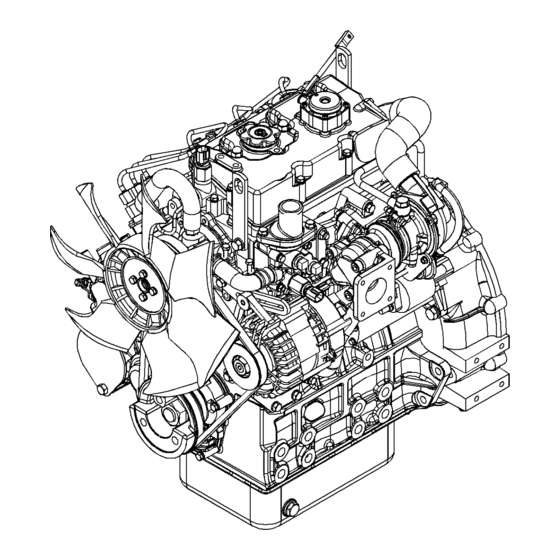
Model Views i08066301 Model View Illustrations The following model views show typical features of the 400 series engines. Due to individual applications, your engine may appear different from the illustrations. Note: Individual components are detailed on the 404D-22T turbocharged engine only. - Page 16 SEBU8311-09 Product Information Section Model View Illustrations Illustration 12 g01300431 Typical view of the 403D-15T engine...
- Page 17 SEBU8311-09 Product Information Section Model View Illustrations Illustration 13 g01304893 Front and right side view of the 404D-22T Engine (1) Fuel shutoff solenoid (5) Throttle lever (9) Engine oil filter (2) Number one fuel injector (6) Cover plate for the accessory drive (10) Fuel injection pump (3) Water pump (7) Engine oil level gauge...
- Page 18 SEBU8311-09 Product Information Section Model View Illustrations Illustration 14 g01305224 Front and left side view of the 404D-22T Engine (13) Top engine oil filler cap (19) Water temperature regulator housing (25) Fan drive belt (14) Crankcase breather (20) Starting motor solenoid (26) Crankshaft pulley (15) Rear Lifting eye (21) Electric starting motor...
- Page 19 (3) Radiator drain plug 402D-05 Engine i06782463 Engine Description The 400 series engines are built in several different variants. Naturally aspirated, turbocharged, and turbocharge aftercooled. The engine range covers two cylinder, three cylinder and four cylinder engines. The 400 series engines can be operated as variable speed or can operate as constant speed engines.
- Page 20 SEBU8311-09 Product Information Section Engine Description Table 1 402D-05 Engine Specifications (Table 2, contd) Maximum Operating Speed Aspiration 3600 rpm (rpm) Compression Ratio 23.5:1 Cylinders and Arrangement In-Line two cylinder Firing Order 1-2-3 Bore 67 mm (2.64 inch) Rotation that is viewed from the Counterclockwise flywheel Stroke...
- Page 21 SEBU8311-09 Product Information Section Engine Description 403D-15T Engine (Table 3, contd) Valve Lash Setting (Inlet) 0.20 mm (0.008 inch) Valve Lash Setting (Exhaust) 0.20 mm (0.008 inch) Injection Indirect Naturally Aspirated 403D-15 Engine Illustration 20 g00852304 (A) Exhaust valves (B) Inlet valves Table 5 403D-15T Engine Specifications Maximum Operating Speed...
- Page 22 SEBU8311-09 Product Information Section Engine Description 403D-17 Engine 404D-15 Engine Illustration 21 g00852304 Illustration 22 g00296424 (A) Exhaust valves (A) Exhaust valves (B) Inlet valves (B) Inlet valves Table 6 Table 7 403D-17 Engine Specifications 404D-15 Engine Specifications Maximum Operating Speed Maximum Operating Speed 2600 rpm 3000 rpm...
- Page 23 SEBU8311-09 Product Information Section Engine Description 404D-22 Engine 404D-22T Engine Illustration 23 g00296424 Illustration 24 g00296424 (A) Exhaust valves (A) Exhaust valves (B) Inlet valves (B) Inlet valves Table 8 Table 9 404D-22 Engine Specifications 404D-22T Engine Specifications Maximum Operating Speed Maximum Operating Speed 3000 rpm 3000 rpm...
- Page 24 Aftermarket Products and Perkins Engines Perkins does not warrant the quality or performance of non-Perkins fluids and filters. When auxiliary devices, accessories, or consumables (filters, additives, catalysts), which are...
-
Page 25: Product Identification Information
Reference Numbers Engine Identification Information for the following items may be needed to Perkins engines are identified by a serial number. order parts. Locate the information for your engine. This number is shown on a serial number plate that is Record the information in the appropriate space. - Page 26 Refer to illustration 28 . The equipment manufacturer must install the label to the equipment. This procedure is recommended by Perkins Small Engines Limited. The label must be attached to the equipment near the fuel inlet to comply with the EPA regulations.
-
Page 27: Operation Section
If alterations are made, ensure that correct lifting devices are provided. Consult your Perkins dealer or your Perkins distributor for information regarding fixtures for correct engine lifting. Illustration 29... - Page 28 The engine must be stored in a water proof building. The building must be kept at a constant temperature. Engines that are filled with Perkins ELC will have coolant protection to an ambient temperature of −36° C (−32.8° F). The engine must not be subjected...
- Page 29 SEBU8311-09 Operation Section Engine Storage Storage Period Monthly Checks An engine can be stored for up to 6 months provided The crankshaft must be rotated to change the spring all the recommendation are adhered to. loading on the valve train. Rotate the crankshaft more than 180 degrees.
-
Page 30: Gauges And Indicators
Ammeter – This gauge indicates the Determine and correct the cause of any significant amount of charge or discharge in the change in the readings. Consult your Perkins dealer battery charging circuit. Operation of or your Perkins distributor for assistance. -
Page 31: Features And Controls
SEBU8311-09 Operation Section Features and Controls Features and Controls i02593769 Fuel Shutoff The fuel shutoff solenoid is located on the fuel injection pump. When the fuel shutoff solenoid is activated, the solenoid moves the fuel rack to the “OFF” position. Illustration 32 g01305771 (1) Fuel shutoff solenoid... -
Page 32: Engine Starting
SEBU8311-09 Operation Section Engine Starting Engine Starting • Do not start the engine or move any of the controls if there is a “DO NOT OPERATE” warning tag or similar warning tag attached to the start switch or i02194223 to the controls. Before Starting Engine •... - Page 33 SEBU8311-09 Operation Section Starting the Engine • Ensure that the engine has an adequate fuel supply. • Open the fuel supply valve (if equipped). If the engine has not been started for several weeks, fuel may have drained from the fuel system. Air may have entered the filter housing.
- Page 34 SEBU8311-09 Operation Section Starting with Jump Start Cables 5. Immediately after the stalled engine is started, i02177935 disconnect the jump start cables in reverse order. Starting with Jump Start After jump starting, the alternator may not be able to Cables fully recharge batteries that are severely discharged.
-
Page 35: Engine Operation
Fuel Conservation Practices The efficiency of the engine can affect the fuel economy. Perkins design and technology in manufacturing provides maximum fuel efficiency in all applications. Follow the recommended procedures in order to attain optimum performance for the life of the engine. -
Page 36: Engine Stopping
SEBU8311-09 Operation Section Engine Stopping Engine Stopping i03756631 After Stopping Engine i06832774 Stopping the Engine Note: Before you check the engine oil, do not operate the engine for at least 10 minutes in order to allow the engine oil to return to the oil pan. NOTICE •... -
Page 37: Cold Weather Operation
Cold Weather Operation • Install the correct specification of engine lubricant before the beginning of cold weather. Perkins Diesel Engines can operate effectively in • Check all rubber parts (hoses, fan drive belts.) cold weather. During cold weather, the starting and weekly. - Page 38 An electric block heater can be activated once the • Pushrods may become bent. engine is stopped. An effective block heater is typically a 1250/1500 W unit. Consult your Perkins • Other damage to valve train components can dealer or your Perkins distributor for more result.
- Page 39 Pour point is the last temperature before the fuel flow dissipation. stops and waxing of the fuel will start. Note: Perkins discourages the use of all air flow Be aware of these properties when diesel fuel is restriction devices such as radiator shutters.
- Page 40 SEBU8311-09 Operation Section Fuel Related Components in Cold Weather i01903588 Fuel Related Components in Cold Weather Fuel Tanks Condensation can form in partially filled fuel tanks. Top off the fuel tanks after you operate the engine. Fuel tanks should contain some provision for draining water and sediment from the bottom of the tanks.
-
Page 41: Maintenance Section
SEBU8311-09 Maintenance Section Refill Capacities Maintenance Section (Table 12, contd) The Total Lubrication System includes the capacity for the Crankcase Oil Sump plus the capacity of factory installed oil fil- ters and other filters added to the lubrication system. Enter the Refill Capacities value for the capacity of the Total Lubrication System in this row. - Page 42 SEBU8311-09 Maintenance Section Refill Capacities (Table 15, contd) (Table 17, contd) These values are the approximate capacities for the crankcase The Total Lubrication System includes the capacity for the oil sump which includes the standard factory installed oil filters. Crankcase Oil Sump plus the capacity of factory installed oil fil- Engines with auxiliary oil filters will require more oil.
- Page 43 By use of this document you agree that Engine plus the External System. Enter the value for the ca- Perkins Engines Company Limited is not responsible pacity of the Total Cooling System in this row. for errors or omissions.
- Page 44 The fuel must meet the minimum requirements that are stated in tables 24 , 25 and 26 . NOTICE The footnotes are a key part of the Perkins Specifica- tion for Distillate Diesel Fuel Table. Read ALL of the footnotes. Table 24...
- Page 45 Regional regulations, national regulations or international regulations can require a fuel with a specific sulfur limit. Consult all applicable regu- lations before selecting a fuel for a given engine application. Perkins fuel systems and engine components can operate on high sulfur fuels in territories that are non-emissions regulated.
- Page 46 D5453, ASTM D2622, or ISO 20846 ISO 20884”, the content of sulfur in ultra low sulfur (ULSD) fuel must Perkins recommends a value of density of 841 kg/m be below 15 PPM 0.0015%. The lubricity of these in order to obtain the correct power output. Lighter...
- Page 47 SEBU8311-09 Maintenance Section Fuel Specification The lubricity has particular significance to the current • “BS2869 Class A2” Off-Highway Gas Oil Red low viscosity fuel, low sulfur fuel and low aromatic Diesel fossil fuel. These fuels are made in order to meet stringent exhaust emissions.
- Page 48 (0.0181 inch). The fuel lubricity test must be biodiesel in any Perkins engine that is regulated by performed on a HFRR, operated at 60 °C (140 °F). emissions standards. Biodiesel that meets Refer to “ISO 12156-1 ”.
- Page 49 Fuel that complies with “EN590” CLASS 4 can be used at temperatures as low as −44 °C (−47.2 °F). Perkins recognizes the fact that additives may be Refer to “EN590” for a detailed discretion of the required in some special circumstances. Fuel physical properties of the fuel.
- Page 50 SEBU8311-09 Maintenance Section Fluid Recommendations Water Note: For the best results, your fuel supplier should treat the fuel when additives are required. The Water is used in the cooling system to transfer heat. treated fuel must meet the requirements that are stated in tables 24 , 25 and 26 .
- Page 51 SEBU8311-09 Maintenance Section Coolant Specifications • Leakage of the water pump seal The following two coolants are used in Perkins diesel engines: • Plugging of radiators, coolers, and small passages Preferred – Perkins ELC Glycol Acceptable – A commercial heavy-duty antifreeze Glycol in the coolant helps to provide protection that meets “ASTM D6210”...
- Page 52 Perkins ELC and operate the engine (SCA). ensure that the thermostat opens. Stop the engine and allow to cool. When using Perkins ELC, do not use standard SCA's or SCA filters. 5. Drain the cooling system. NOTICE ELC Cooling System Cleaning...
- Page 53 SCA that is required when the cooling ness of the ELC and shortens the ELC service life. system is initially filled. Use only Perkins Products for premixed or concen- trate coolants. Failure to follow these recommenda- Table 33...
- Page 54 “SAE J754”. Some classifications follow “SAE J183” • Clean the cooling system after used coolant is abbreviations. In addition to Perkins definitions, there are other definitions that will be of assistance in drained or before the cooling system is filled with purchasing lubricants.
- Page 55 API CH-4 oils are recommended for Excessive piston deposits can be produced by an oil conditions that demand a premium oil. Your Perkins with a high TBN. These deposits can lead to a loss of distributor has specific guidelines for optimizing oil control of the oil consumption and to the polishing of change intervals.
- Page 56 Re-refined Base Stock Oils Aftermarket Oil Additives Re-refined base stock oils are acceptable for use in Perkins engines if these oils meet the performance Perkins does not recommend the use of aftermarket requirements that are specified by Perkins. Re- additives in oil. It is not necessary to use aftermarket...
- Page 57 The aftermarket additive could fail to mix with the finished oil. This action could produce sludge in the crankcase. Perkins discourages the use of aftermarket additives in finished oils. To achieve the best performance from a Perkins engine, conform to the following guidelines: •...
-
Page 58: Maintenance Recommendations
Consult the OEM of the equip- To relieve the pressure from the coolant system, turn ment or your Perkins dealer regarding welding on a off the engine. Allow the cooling system pressure cap chassis frame or rail. - Page 59 SEBU8311-09 Maintenance Section Welding on Engines with Electronic Controls 3. Disconnect the J1/P1 and J2/P2 connectors from the ECM. Move the harness to a position that will not allow the harness to accidentally move back and make contact with any of the ECM pins. Illustration 37 g01143634 4.
-
Page 60: Maintenance Interval Schedule
SEBU8311-09 Maintenance Section Maintenance Interval Schedule “ Radiator - Clean“ ......90 i08156304 Maintenance Interval Schedule Every 1000 Service Hours “... - Page 61 SEBU8311-09 Maintenance Section Aftercooler Core - Clean/Test 10. Install the core. Refer to the OEM information for i03632383 the correct procedure. Aftercooler Core - Clean/Test 11. After cleaning, start the engine and accelerate the (Air-To-Air Aftercooler) engine to high idle rpm. This will help in the removal of debris and drying of the core.
- Page 62 Maintenance Section Alternator - Inspect i02322311 Alternator - Inspect Perkins recommends a scheduled inspection of the alternator. Inspect the alternator for loose connections and correct battery charging. Check the ammeter (if equipped) during engine operation in order to ensure correct battery performance and/or correct performance of the electrical system.
- Page 63 SEBU8311-09 Maintenance Section Alternator and Fan Belts - Replace 2. Move the alternator in order to increase or 3. Push alternator (3) toward the engine and remove decrease the belt tension. V-belt (5) from the pulleys. 3. Tighten adjusting bolt (1). Tighten mounting bolts Installation Procedure (2).
- Page 64 SEBU8311-09 Maintenance Section Battery - Replace 4. If the engine is equipped with fan guards, install 7. Connect the cable from the starting motor to the the fan guards. Refer to the OEM for the correct POSITIVE “+” battery terminal. installation procedure 8.
- Page 65 SEBU8311-09 Maintenance Section Battery or Battery Cable - Disconnect i07819485 i08056195 Battery or Battery Cable - Cooling System Coolant Disconnect (Commercial Heavy-Duty) - Change NOTICE The battery cables or the batteries should not be Care must be taken to ensure that fluids are con- removed with the battery cover in place.
- Page 66 Perkins to reclaim the coolant. For information regarding the disposal and the recycling of used coolant, consult your Perkins dealer or your Perkins distributor. Flush 1. Flush the cooling system with clean water to remove any debris.
- Page 67 SEBU8311-09 Maintenance Section Cooling System Coolant (ELC) - Change 3. Fill the cooling system with Commercial Heavy- NOTICE Duty Coolant. Add Supplemental Coolant Additive Keep all parts clean from contaminants. to the coolant. For the correct amount, refer to the Contaminants may cause rapid wear and shortened Operation and Maintenance Manual, “Fluid component life.
- Page 68 Perkins to reclaim the coolant. For information regarding the disposal and the recycling of used coolant, consult your Perkins dealer or your Perkins distributor. Flush 1. Flush the cooling system with clean water to remove any debris.
- Page 69 Cooling System Coolant Level - Check Engines With a Coolant Recovery Tank Note: The cooling system may not have been provided by Perkins. The procedure that follows is for Illustration 46 g02590196 typical cooling systems. Refer to the OEM Filler cap information for the correct procedures.
- Page 70 SEBU8311-09 Maintenance Section Cooling System Supplemental Coolant Additive (SCA) - Test/Add Note: The coolant will expand as the coolant heats 4. Inspect the cooling system for leaks. up during normal engine operation. The additional volume will be forced into the coolant recovery tank i03644948 during engine operation.
- Page 71 Note: Always discard drained fluids according to Perkins engines incorporate a shunt design cooling local regulations. system and require operating the engine with a water temperature regulator installed.
- Page 72 Note: The air filter system may not have been Steam cleaning the engine will remove accumulated provided by Perkins. The procedure that follows, is oil and grease. A clean engine provides the following for a typical air filter system. Refer to the OEM benefits: information for the correct procedure.
- Page 73 SEBU8311-09 Maintenance Section Engine Air Cleaner Service Indicator - Inspect 6. Install end cover (4) to air cleaner body (2) and secure end cover. If necessary, reset the air service indicator, refer to this Operation and Maintenance Manual, Engine Air Cleaner Service Indicator - Inspect for more information.
- Page 74 SEBU8311-09 Maintenance Section Engine Air Precleaner - Check/Clean • Check the movement of the yellow core when the i02657627 engine is accelerated to the engine rated speed. Engine Crankcase Breather - The yellow core should latch at the greatest vacuum that is attained. Replace If the service indicator does not reset easily, or if the yellow core does not latch at the greatest vacuum,...
- Page 75 NOTICE Care must be taken to ensure that fluids are con- When the engine mounts are supplied by Perkins the tained during performance of inspection, mainte- maintenance procedure will be supplied in the nance, testing, adjusting and repair of the product.
- Page 76 SEBU8311-09 Maintenance Section Engine Oil and Filter - Change Do not drain the oil when the engine is cold. As the oil cools, suspended waste particles settle on the bottom of the oil pan. The waste particles are not removed with the draining cold oil. Drain the crankcase with the engine stopped.
- Page 77 Replace the Oil Filter NOTICE Perkins oil filters are built to Perkins specifications. Use of an oil filter not recommended by Perkins could result in severe engine damage to the engine bear- ings, crankshaft, etc., as a result of the larger waste particles from unfiltered oil entering the engine lubri- cating system.
- Page 78 Regular maintenance of the fuel injectors is recommended by Perkins. The fuel injectors must be NOTICE Only qualified service personel should perform this removed and tested by an authorized agent. The fuel maintenance.
- Page 79 SEBU8311-09 Maintenance Section Fuel System - Prime • The engine will not start or the engine is difficult to Consult your authorized Perkins dealer or your Perkins distributor for further assistance. start. • Not enough power i08046563 • The engine misfires or the engine runs erratically.
- Page 80 SEBU8311-09 Maintenance Section Fuel System - Prime Illustration 58 g01316878 Illustration 59 g01327360 This filter may not be installed on the engine. Element (1) Vent screws (2) Fuel valve (3) Vent screw Fuel filters There are three types of fuel filter that may be installed on the engine.
- Page 81 SEBU8311-09 Maintenance Section Fuel System - Prime Illustration 61 g01327363 Spin-on filter with fuel priming pump (5) Vent screw Vent screw (3) is installed on the filter that has an element. Vent screw (4) is installed on the fuel filter that has a canister.
- Page 82 SEBU8311-09 Maintenance Section Fuel System - Prime Illustration 62 g06523817 (6) Hand priming pump (8) Electrical priming pump (7) In-line priming pump (9) Fuel transfer pump with hand priming Illustration 63 g06523835 (10) Connector bolt (11) Fuel return line (12) Connector bolt Hand Priming Pump 6 1.
- Page 83 SEBU8311-09 Maintenance Section Fuel System - Prime 2. Loosen vent screw (3 4 or 5) on the fuel filter. 1. Ensure that fuel valve (2) for the fuel filter that has an element is in the ON position. Refer to 3.
- Page 84 SEBU8311-09 Maintenance Section Fuel System Filter - Replace Note: Do not operate the starting motor for more than 15 seconds. If the engine does not start after 15 seconds, stop and wait for 30 seconds before trying again. i08046690 Fuel System Filter - Replace Fuel leaked or spilled onto hot surfaces or electri- cal components can cause a fire.
- Page 85 SEBU8311-09 Maintenance Section Fuel System Filter - Replace 6. Fasten the assembly to the fuel filter base with setscrew (2). 7. Open the fuel supply valve. The fuel system will need to be primed after the new filter is installed. Refer to this Operation and Maintenance Manual, “Fuel System - Prime”...
- Page 86 SEBU8311-09 Maintenance Section Fuel System Filter - Replace The fuel system will need to be primed after the new filter is installed. Refer to this Operation and Maintenance Manual, “Fuel System - Prime” for the correct procedure. In Line Fuel Filter Illustration 68 g01306131 Typical example...
- Page 87 SEBU8311-09 Maintenance Section Fuel System Primary Filter - Replace The fuel system will need to be primed after the new filter is installed. Refer to this Operation and Maintenance Manual, “Fuel System - Prime” for the correct procedure. i05337705 Fuel System Primary Filter - Replace Fuel leaked or spilled onto hot surfaces or electri- cal components can cause a fire.
- Page 88 SEBU8311-09 Maintenance Section Fuel System Primary Filter/Water Separator - Drain 6. Clean the filter bowl (4). 4. The secondary fuel filter must be replaced at the same time as the primary fuel filter. Refer to the Install the Element Operation and Maintenance Manual , “Fuel System Secondary Filter - Replace”.
- Page 89 SEBU8311-09 Maintenance Section Fuel Tank Water and Sediment - Drain Some fuel tanks use supply pipes that allow water i02335436 and sediment to settle below the end of the fuel Fuel Tank Water and Sediment supply pipe. Some fuel tanks use supply lines that take fuel directly from the bottom of the tank.
- Page 90 • Anticipated expansion and contraction of the hose • Anticipated expansion and contraction of the fittings The radiator is not usually supplied by Perkins. The following text describes a typical cleaning procedure Replace the Hoses and the Clamps for the radiator. Refer to the OEM information for further information on cleaning the radiator.
- Page 91 • The temperature of the fluid in the engine • Failure to use recommended fuel, lubricants and Refer to the standards for the engine or consult your coolant/antifreeze Perkins dealer or your Perkins distributor in order to determine if the engine is operating within the defined i07888480 parameters.
- Page 92 Adjusting Manual, “Electric Starting System - Assembly Manual, “Turbocharger - Remove and Test” for more information on the checking procedure Turbocharger - Install” for further information. and for specifications consult your Perkins dealer or your Perkins distributor for assistance. Inspecting i02184788...
- Page 93 “Water Pump - Remove and Install” for more and parts contract. information or consult your Perkins dealer or your Perkins distributor. Visually inspect the water pump for leaks. Renew the water pump seal or the water pump if there is an •...
-
Page 94: Warranty Section
This engine may be covered by an Emissions Warranty. Consult your authorized Perkins dealer or distributor to determine if your engine is emissions certified and if your engine is subject to an Emissions... -
Page 95: Index
Engine Air Precleaner - Check/Clean ..... 74 Diesel Fuel ............11 Engine Crankcase Breather - Replace ... 74 Oils..............11 Engine Description .......... 19 Aftermarket Products and Perkins Engines ............24 Engine Specifications ........19 Cold Weather Operation ......... 37 Service Life ..........24 Hints for Cold Weather Operation .... - Page 96 SEBU8311-09 Index Section Fire Prevention and Explosion Prevention..11 Ether ............12 Gauges and Indicators ........30 Fire Extinguisher.......... 12 General Hazard Information......8 Lines, Tubes, and Hoses ......12 Containing Fluid Spillage....... 9 Fluid Recommendations ......... 54 Fluid Penetration ........... 9 Engine Oil ............
- Page 97 SEBU8311-09 Index Section Radiator - Clean ..........90 Reference Numbers ........25 Record for Reference ........25 Refill Capacities..........41 Cooling System..........42 Lubrication System ........41 Safety Messages..........6 (A) Universal Warning........6 Safety Section ........... 6 Serial Number Plate ........25 Severe Service Application - Check....
- Page 99 Product and Dealer Information Note: For product identification plate locations, see the section “Product Identification Information” in the Operation and Maintenance Manual. Delivery Date: Product Information Model: Product Identification Number: Engine Serial Number: Transmission Serial Number: Generator Serial Number: Attachment Serial Numbers: Attachment Information: Customer Equipment Number: Dealer Equipment Number:...
- Page 100 SEBU8311 ©2020 Perkins Engines Company Limited All Rights Reserved June 2020...
Need help?
Do you have a question about the 400 Series and is the answer not in the manual?
Questions and answers