Perkins 403C-11 Workshop Manual
Hide thumbs
Also See for 403C-11:
- Workshop manual (129 pages) ,
- Operation and maintenance manual (80 pages) ,
- Operation and maintenance manual (88 pages)
Table of Contents
Advertisement
Quick Links
Perkins 400 Series
Models 403C-11, 403C-15, 404C-22 and 404C-22T
WORKSHOP MANUAL
403C-11
403C-15
404C-22
404C-22T
Perkins Confidential: Green
Publication TPD 1458E, Issue 3.
© Proprietary information of Perkins Engines Company Limited, all rights reserved.
The information is correct at the time of print.
Published in September 2002 by Technical Publications.
Three cylinder naturally aspirated diesel
engine
Three cylinder naturally aspirated diesel
engine
Four cylinder naturally aspirated diesel
engine
Four cylinder turbo charged diesel engine
i
Advertisement
Table of Contents

Related Manuals for Perkins 403C-11


Summary of Contents for Perkins 403C-11
- Page 1 Four cylinder turbo charged diesel engine Perkins Confidential: Green Publication TPD 1458E, Issue 3. © Proprietary information of Perkins Engines Company Limited, all rights reserved. The information is correct at the time of print. Published in September 2002 by Technical Publications.
-
Page 2: Table Of Contents
7KLV SXEOLFDWLRQ LV ZULWWHQ LQ 3HUNLQV $SSURYHG &OHDU (QJOLVK Chapters 1 General information 2 Specifications 3 Cylinder head assembly 4 Piston and connecting rod assemblies 5 Crankshaft assembly 6 Timing case and drive assembly 7 Cylinder block assembly 8 Engine timing 9 Aspiration system 10 Lubrication system 11 Fuel system... - Page 3 Operation 3-2 To remove and to fit ................14 Workshop Manual TPD 1458E, issue 3 - Perkins Confidential: Green...
- Page 4 Operation 3-20 To check and to adjust ..............32 Workshop Manual TPD 1458E, issue 3 - Perkins Confidential: Green...
- Page 5 Operation 5-3 To inspect for deflection ..............47 Workshop Manual TPD 1458E, issue 3 - Perkins Confidential: Green...
- Page 6 ..................62 Workshop Manual TPD 1458E, issue 3 - Perkins Confidential: Green...
- Page 7 Operation 10-2 To remove and to fit ................ 78 Workshop Manual TPD 1458E, issue 3 - Perkins Confidential: Green...
- Page 8 Operation 12-3 To remove and to fit ................ 93 viii Workshop Manual TPD 1458E, issue 3 - Perkins Confidential: Green...
- Page 9 ................111 Wiring diagram - automatic shutdown 15 amp alternator - 403C-11 ...... 112...
- Page 10 400 Series Wiring diagram - automatic shutdown 40 amp alternator - 403C-11 ..... ..113 Wiring diagram - automatic shutdown 55 amp alternator 403C-15, 404C-22 and 404C-22T ..................... ..114...
-
Page 11: General Information
Introduction This workshop manual has been written to provide assistance for technicians who service and overhaul the Perkins 403C-11, 403C-15, 404C-22 and the 404C-22T engine. The assumption is made that the engine is removed from the application. The engine conforms with USA EPA/CARB and EC emissions legislation for agricultural and industrial applications. -
Page 12: Specifications
Do not clean an engine while it runs or while it is hot. If cold cleaning fluids are applied to a hot engine, certain components on the engine could be damaged. l Fit only genuine Perkins parts. Workshop Manual, TPD 1458E, issue 3 - Perkins Confidential: Green... - Page 13 If these cautions are ignored, the engine or certain components could be damaged, fail to operate and also make the manufacturer’s warranty invalid. Workshop Manual, TPD 1458E, issue 3 - Perkins Confidential: Green...
-
Page 14: Powerpart Recommended Consumable Products
400 Series POWERPART recommended consumable products Perkins have made available the products recommended below in order to assist in the correct operation, service and maintenance of your engine and your machine. The instructions for the use of each product are given on the outside of each container. - Page 15 POWERPART Threadlock and nutlock To retain small fasteners where easy removal is necessary. Part number 21820117 or 21820118. POWERPART Universal jointing compound Universal jointing compound which seals joints. Currently Hylomar. Part number 1861117. Workshop Manual, TPD 1458E, issue 3 - Perkins Confidential: Green...
-
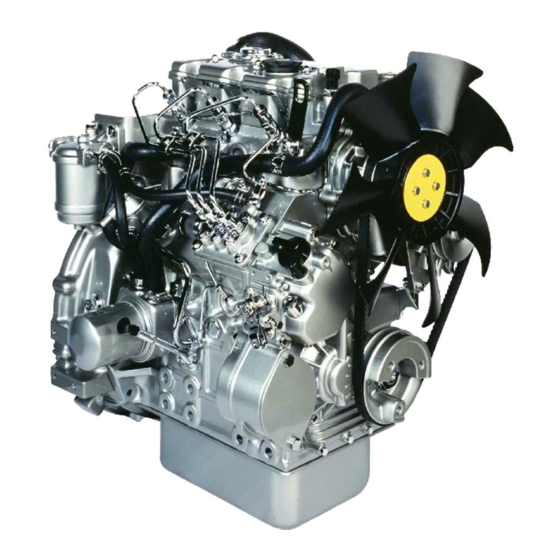
Page 16: Engine Views
400 Series Engine views H1029 H1030 Workshop Manual, TPD 1458E, issue 3 - Perkins Confidential: Green... -
Page 17: Engine Identification
Code IV engine serial number Individual serial number commencing with 000001 increasing numerically. Code V year of manufacture Code Year 2001 2002 Perkins TYPE LIST NO SERIAL NO TYPE H1031 Workshop Manual, TPD 1458E, issue 3 - Perkins Confidential: Green... -
Page 18: Engine Lift Equipment
196 kg Backplate specification 184 kg Long flywheel housing specification 230 kg 404C-22T Short flywheel housing specification 206 kg Backplate specification 194 kg (1) Engine may alter with final specification. H1032 Workshop Manual, TPD 1458E, issue 3 - Perkins Confidential: Green... -
Page 19: Specifications
352 - 448 kPa pressure relief valve Lubricating oil pressure switch 49,0 kPa 29,4 kPa located on top cover Lubricating oil pressure switch 49,0 kPa 98,0 kPa located on cylinder block oil rail Workshop Manual, TPD 1458E, issue 3 - Perkins Confidential: Green... -
Page 20: Standard Torques
1,25 1,25 1,75 1,25 10,6 11,5 12,0 13,5 16,0 17,0 17,0 17,8 23,4 25,0 Bolt strength Examples of applicable material S45C SCM435 Workshop Manual, TPD 1458E, issue 3 - Perkins Confidential: Green... -
Page 21: Special Torques
33 (24.3) 3,3 Rocker cover 14 (10.3) 1,4 Electrical shut off solenoid 18 (13.2) 1,8 Sump drain plug 35 (25.8) 3,5 Temperature switch 27 (19.9) 2,7 Thermostat setscrew 14 (10.3) 1,4 Workshop Manual, TPD 1458E, issue 3 - Perkins Confidential: Green... -
Page 22: Compression Test Data
4 Disconnect the stop solenoid or put the stop solenoid in the no fuel position. Operate the starter motor and record the pressure indicated on the gauge. Caution: Do not remove the stop solenoid as this will allow the engine to start. 5 Repeat for each cylinder. H1033 Workshop Manual, TPD 1458E, issue 3 - Perkins Confidential: Green... -
Page 23: Cylinder Head Assembly
Setscrew 14 (10.3) 1,4 404C-22T Notes: l An ‘O’ ring (1) is fitted in the groove in the rocker cover. l Inspect the ‘O’ ring and renew if necessary. H1034 Workshop Manual, TPD 1458E, issue 3 - Perkins Confidential: Green... -
Page 24: Rocker Assembly Operation 3-2 To Remove And To Fit
Caution: Ensure that the valve stem caps are on the valve stems and the pushrods are located in the rockers after assembly. Note: An ‘O’ ring (1) is fitted in the groove in the rocker assembly. H1035 Workshop Manual, TPD 1458E, issue 3 - Perkins Confidential: Green... - Page 25 Torque Nm (lbf ft) kgf m All models Tappet adjustment nut 14 (10.3) 1,4 Use a suitable puller to extract the rocker shaft. Note: Remember the position of the recess (1) for assembly. H1036 Workshop Manual, TPD 1458E, issue 3 - Perkins Confidential: Green...
- Page 26 Rocker shaft to rocker lever clearance Clearance mm (in) Engine Standard Service limit 403C-11 0,032 - 0,068 (0.00126 - 0.00268) 0,2 (0.008) 403C-15 404C-22 0,030 - 0,093 (0.00120 - 0.00366) 0,2 (0.008) 404C-22T H1037 Workshop Manual, TPD 1458E, issue 3 - Perkins Confidential: Green...
- Page 27 Operation 3-5 Engine Torque Nm (lbf ft) kgf m Setscrew 9,8 (7.2) 0,9 403C-11 Nuts 9,8 (7.2) 0,9 403C-15 Setscrew 25 (18.4) 2,5 404C-22 Nuts 25 (18.4) 2,5 404C-22T H1038 Workshop Manual, TPD 1458E, issue 3 - Perkins Confidential: Green...
- Page 28 Fuel injection pipes / fuel return pipes To remove and to fit Operation 3-6 Engine Torque Nm (lbf ft) kgf m Fuel injection pipe 23 (16.9) 2,3 All models Banjo bolt (1) 2,5 (3.2) 0,25 H1039 Workshop Manual, TPD 1458E, issue 3 - Perkins Confidential: Green...
- Page 29 Note: If it is necessary to replace the cylinder head the fuel adjustment screw must not be altered from the original setting. The maximum no load speed must be checked after assembly. H1040 Workshop Manual, TPD 1458E, issue 3 - Perkins Confidential: Green...
- Page 30 51 (37.6) 5,2 403C-15 Cylinder head setscrews 101 (74.5) 10,3 Notes: l All torques should be checked again after tightening. l On assembly lubricate cylinder head setscrews with clean oil. H1041 Workshop Manual, TPD 1458E, issue 3 - Perkins Confidential: Green...
- Page 31 Torque Nm (lbf ft) kgf m 404C-22 Cylinder head setscrews 101 (74.5) 10,3 404C-22T Notes: l All torques should be checked again after tightening. l On assembly lubricate cylinder head setscrews with clean oil. H1042 Workshop Manual, TPD 1458E, issue 3 - Perkins Confidential: Green...
- Page 32 The correct piston height must be maintained to prevent damage to the pistons and valves and ensure that the engine conforms to emission legislation. Note: Always fit dry. H1043 Workshop Manual, TPD 1458E, issue 3 - Perkins Confidential: Green...
- Page 33 1,3 mm 403C-15 0,70 to 0,79 1,4 mm Engine Protrusion below cylinder block top face Gasket thickness -0,45 to -0,30 0,4 mm 404C-22 404C-22T -0,29 to -0,20 0,5 mm H1044 Workshop Manual, TPD 1458E, issue 3 - Perkins Confidential: Green...
- Page 34 The oil seal for the exhaust valve stem is identified by a black garter spring (not shown) with the letters “EX” on the garter. Warning! Safety glasses must be worn for this operation. H1045 Workshop Manual, TPD 1458E, issue 3 - Perkins Confidential: Green...
- Page 35 35,0 (1.378) 33,5 (1.319) Spring rate when compressed to 30,4 mm (1.197 in) N (lbf) kgf Engine Standard Service limit All models 79 (17.8) 8,1 68,6 (15.4) 7,0 Worn H1046 Workshop Manual, TPD 1458E, issue 3 - Perkins Confidential: Green...
- Page 36 Engine Standard Service limit All models 0,925 - 1,075 (0.03642 - 0.04232) 0,5 (0.020) If the valve head thickness (4) is less than the service limit, renew the valve. H1047 Workshop Manual, TPD 1458E, issue 3 - Perkins Confidential: Green...
- Page 37 Exhaust valve Engine Clearance mm (in) standard Service limit 403C-11 0,045 - 0,072 (0.0020 - 0.0030) 0,25 (0.010) 403C-15, 404C-22 and 404C-22T 0,050 - 0,075 (0.0020 - 0.0030) 0,25 (0.010) H1048 Workshop Manual, TPD 1458E, issue 3 - Perkins Confidential: Green...
- Page 38 0,05 (0.002) or less 0,12 (0.005) 0,15 (0.006) Use a straight edge and feeler gauge to check the six positions for distortion. Caution: Do not grind beyond the maximum limit. H1049 Workshop Manual, TPD 1458E, issue 3 - Perkins Confidential: Green...
- Page 39 If the bore in the cylinder head for the valves is worn, replace the cylinder head. If the valve seat in the cylinder head is damaged or worn, cut a new seat if the valve depth will remain within tolerance. 45° Contact Width H1050 Workshop Manual, TPD 1458E, issue 3 - Perkins Confidential: Green...
- Page 40 0,85 - 1,15 (0.0335 - 0.0453) 0,85 - 1,15 (0.0335 - 0.0453) 1,8 (0.071) 404C-22 0,65 - 0,95 (0.0256 - 0.0374) 0,65 - 0,95 (0.0256 - 0.0374) 1,8 (0.071) 404C-22T H1051 Workshop Manual, TPD 1458E, issue 3 - Perkins Confidential: Green...
- Page 41 Use the valve seat cutter to obtain the correct seat contact width and seat recess on a new cylinder head, use a valve lapping tool and lapping compound to finish. H1052 Workshop Manual, TPD 1458E, issue 3 - Perkins Confidential: Green...
- Page 42 3 and 4 Valve tip clearance (cold) Inlet 0,2 mm (0.0078 in) Exhaust 0,2 mm (0.0078 in) Torque Nm (lbf ft) kgf m Tappet adjustment nut 14 (10.3) 1,4 H1053 Workshop Manual, TPD 1458E, issue 3 - Perkins Confidential: Green...
-
Page 43: Piston And Connecting Rod Assemblies
After the connecting rods are fitted check for axial movement. l The fuel adjustment screw must not be altered from the original setting. The maximum no load speed must be checked after assembly. H1054 Workshop Manual, TPD 1458E, issue 3 - Perkins Confidential: Green... -
Page 44: Piston And Connecting Rod
To remove and to fit Operation 4-2 The Shibaura name on the inside of the piston must be facing the fuel pump on assembly. To assemble the connecting rod assembly, see page 35. H1055 Workshop Manual, TPD 1458E, issue 3 - Perkins Confidential: Green... - Page 45 The Shibaura (1) name (inside of the piston) must be aligned with the stamped number on the connecting rod (1). The numbers stamped on the connecting rods and caps must be the same and aligned. H1056 Workshop Manual, TPD 1458E, issue 3 - Perkins Confidential: Green...
-
Page 46: Piston Rings
New top rings have a red identification mark which must be on the left of the ring gap when the ring is fitted and the piston is upright. 4 Ensure that the ring gaps are 90° apart. 90° 90° H1057 Workshop Manual, TPD 1458E, issue 3 - Perkins Confidential: Green... - Page 47 0,04 - 0,08 mm Number 2 ring 0,25 (0.0098 in) (0.0016 - 0.0032 in) 404C-22T 0,02 - 0,06 mm Oil control ring 0,15 (0.0059 in) (0.0008 - 0.0024 in) H1058 Workshop Manual, TPD 1458E, issue 3 - Perkins Confidential: Green...
- Page 48 0,20 - 0,40 mm (0.0079 - 0.0158 in) 1,0 mm (0.039 in) 404C-22T Oil control ring 0,20 - 0,40 mm (0.0079 - 0.0158 in) 1,0 mm (0.039 in) à á H1059 Workshop Manual, TPD 1458E, issue 3 - Perkins Confidential: Green...
- Page 49 Service limit 403C-11 -0,004 - +0,004 mm (-0.00016 - +0.00016 in) 0,02 mm (0.0008 in) 403C15 404C-22 -0,001 - +0,007 mm (-0.00040 - +0.00030 in) 0,02 mm (0.0008 in) 404C-22T Workshop Manual, TPD 1458E, issue 3 - Perkins Confidential: Green...
-
Page 50: Piston And Piston Ring
Service limit 403C-11 0,0525 - 0,0865 mm (0.00210 - 0.00340 in) 0,25 mm (0.010 in) 403C-15 404C-22 0,0380 - 0,0720 mm (0.00150 - 0.00283 in) 0,25 mm (0.010 in) 404C-22T Workshop Manual, TPD 1458E, issue 3 - Perkins Confidential: Green... -
Page 51: Connecting Rod
Check the fit of the gudgeon pin in the small end bush and check the gudgeon pin for wear. 100 mm 100 mm (3.937 in) (3.937 in) ± 0,08 mm ± 0,08 mm (0,0031 in) (0,0031 in) H1060 Workshop Manual, TPD 1458E, issue 3 - Perkins Confidential: Green... -
Page 52: Connecting Rod Bearing Clearance
0,029 - 0,082 mm (0.00110 - 0.00320 in) 0,20 mm (0.0079 in) 403C-15, 404C-22 and 404C-22T 0,035 - 0,085 mm (0.00138 - 0.00335 in) 0,20 mm (0.0079 in) INCH H1066 Workshop Manual, TPD 1458E, issue 3 - Perkins Confidential: Green... -
Page 53: Small End Bush
Engine Clearance mm (in) Service limit mm (in) 403C-11 0,010 - 0,025 (0.00040 - 0.00099) 0.08 (0.0031) 403C-15 404C-22 0,010 - 0,025 (0.00040 - 0.00099) 0,10 (0.0040) 404C-22T H1061 Workshop Manual, TPD 1458E, issue 3 - Perkins Confidential: Green... - Page 54 This page is intentionally blank...
-
Page 55: Crankshaft Assembly
403C-11 Crankshaft nut 123 (90.7) 12,5 403C-15 Crankshaft pulley remover 21825619 404C-22 Crankshaft nut 304 (224.2) 30,9 404C-22T Note: Store the key (1) in a safe place until assembly. H1062 Workshop Manual, TPD 1458E, issue 3 - Perkins Confidential: Green... -
Page 56: Crankshaft Retaining Bolts And Crankshaft
Note: If the crankshaft or crankshaft bearings are replaced the fuel adjustment screw must not be altered from the original setting. The maximum no load speed must be checked after assembly. H1063 Workshop Manual, TPD 1458E, issue 3 - Perkins Confidential: Green... - Page 57 1.6Z (∇ ∇ Finish precision (B2) Radius around oil hole (B3) 2 mm (0.787 in) maximum / 5 mm (0.196 in) minimum Note: Use No. 400 emery cloth for final polishing. H1064 Workshop Manual, TPD 1458E, issue 3 - Perkins Confidential: Green...
- Page 58 Undersize 0,50 mm (0.02 in) 51,464 - 51,475 mm (2.02614 - 2.02660 in) 51,40 mm (2.0236 in) * Note: If the diameter is less than the maximum undersize service limit (*), the crankshaft must be renewed. Workshop Manual, TPD 1458E, issue 3 - Perkins Confidential: Green...
-
Page 59: Main Bearings
Note: Ensure that the thrust washers are aligned correctly, fitted with their oil grooves towards the crankshaft. 4 Check the thrust washers for wear, poor contact or damage, if damaged renew. H1067 Workshop Manual, TPD 1458E, issue 3 - Perkins Confidential: Green... -
Page 60: Bearing Holder
67,957 - 67,970 (2.67550 - 2.67597) Undersize 0,25 (0.01) 1, 2, 3, 4 67,707 - 67,720 (2.66563 - 2.66614) Undersize 0,50 (0.02) 1, 2, 3, 4 67,457 - 67,470 (2.65579 - 2.65630) Workshop Manual, TPD 1458E, issue 3 - Perkins Confidential: Green... -
Page 61: Timing Case And Drive Assembly
Note: If the timing case is renewed, a new emission label must be fitted as shown (2). 1 To remove the PTO cover, see Operation 6-9. 2 To remove and to fit the crankshaft pulley, see Operation 5-1. H1068 Workshop Manual, TPD 1458E, issue 3 - Perkins Confidential: Green... - Page 62 Caution: If the timing case assembly or internal governor components are replaced the fuel adjustment screw should not be adjusted. The maximum no load speed should be checked after assembly. H1069 Workshop Manual, TPD 1458E, issue 3 - Perkins Confidential: Green...
- Page 63 The internal setting for the Angleich must not be altered. l Apply a little Loctite 275 to threads (2) before assembly. l The Angleich is not fitted to the 403C-11 engine. H1070 Workshop Manual, TPD 1458E, issue 3 - Perkins Confidential: Green...
- Page 64 When fitting the timing case care must be taken to ensure correct alignment of the slider contact (1) with the governor lever. Caution: Incorrect alignment of the slider (2) on the pin (3) may result in the loss of engine speed control. H1071 Workshop Manual, TPD 1458E, issue 3 - Perkins Confidential: Green...
-
Page 65: Camshaft Retaining Plate
Note: If the camshaft assembly is replaced the fuel adjustment screw must not be altered from the original setting. The maximum no load speed must be checked after assembly. H1072 Workshop Manual, TPD 1458E, issue 3 - Perkins Confidential: Green... -
Page 66: Camshaft And Tappets
Note: If the camshaft assembly is replaced the fuel adjustment screw must not be altered from the original setting. The maximum no load speed must be checked after assembly. Lubricate the tappets with clean lubricating oil before assembly. H1073 Workshop Manual, TPD 1458E, issue 3 - Perkins Confidential: Green... -
Page 67: Camshaft Assembly
Height of cam for fuel injection pump (3). Engine Height mm (in) Standard Service limit 403C-11 39,900 - 40,100 (1.57090 - 1.57870) 39,8 (1.5669) 403C-15, 404C-22 and 404C-22T 41,940 - 42,060 (1.65120 - 1.65590) 41,8 (1.6450) H1074 Workshop Manual, TPD 1458E, issue 3 - Perkins Confidential: Green... -
Page 68: Maximum Fuel Screw And Maximum Speed Screw
14 (10.3) 1,4 Caution: The fuel adjustment setscrew must be set correctly for the engine to comply with emissions legislation. This must only be carried out by an approved Perkins distributor. Notes: l The maximum fuel setscrew (1) and the maximum speed setscrew (2) must not be adjusted by the operator. -
Page 69: Front Oil Seal And Pto Cover
An ‘O’ ring (1) is fitted in the groove (2) on the front of the timing case. A joint (3) is used on the rear of the timing case PTO cover. H1076 Workshop Manual, TPD 1458E, issue 3 - Perkins Confidential: Green... - Page 70 400 Series Idler gear and oil pump To remove and to fit Operation 6-10 To check the end float, see Operation 6-13. H1094/1 Workshop Manual, TPD 1458E, issue 3 - Perkins Confidential: Green...
-
Page 71: Idler Hub
403C-15 404C-22 Idler hub fitting tool 21825626 404C-22T Caution: Always fit a new idler gear hub, do not fit the old hub, as it may be damaged when removed. H1078 Workshop Manual, TPD 1458E, issue 3 - Perkins Confidential: Green... -
Page 72: Gear Teeth Backlash
0,25 (0.0098) Measure the clearances one at a time with a feeler gauge at each of the locations shown. If the measurement is outside the service limit fit new gears. H1079 Workshop Manual, TPD 1458E, issue 3 - Perkins Confidential: Green... -
Page 73: Oil Pump End Float
Adjust with 0,1 - 0,15 - 0,2 and 0,5 mm shims (1). Engine Standard clearance mm (in) Service limit mm (in) All models 0,10 - 0,15 (0.0040 - 0.0060) 0,20 (0.0079) H1080 Workshop Manual, TPD 1458E, issue 3 - Perkins Confidential: Green... - Page 74 400 Series Governor springs To inspect Operation 6-14 The diagram shows the correct position for the start spring (1) and the governor spring (2). H1081 Workshop Manual, TPD 1458E, issue 3 - Perkins Confidential: Green...
-
Page 75: Cylinder Block Assembly
Use a suitable press to fit the crankshaft bush. Note: The bush must be fitted with the chamfered side (2) towards the cylinder block, with the join (1) at the top. H1082/1 Workshop Manual, TPD 1458E, issue 3 - Perkins Confidential: Green... - Page 76 67,957 - 67,970 mm (2.67550 - 2.67597 in) 403C-15 404C-22 0,25 mm (0.01 in) 67,707 - 67,720 mm (2.66563 - 2.66614 in) 404C-22T 0,50 mm (0.02 in) 67,457 - 67,470 mm (2.65579 - 2.65630 in) H1083 Workshop Manual, TPD 1458E, issue 3 - Perkins Confidential: Green...
-
Page 77: Cylinder Block Top Face
Operation 3-16. If outside service limit, renew the cylinder block. Caution: The fuel adjustment screw must be set by an approved Perkins dealer to ensure that the engine will comply with emissions legislation. If the cylinder block is renewed, the engine must be tested on an engine test brake and the fuel adjustment screw set. -
Page 78: Cylinder Bore
If the bore diameter is larger than the service limit for the engine model listed below, renew the cylinder block with a long engine. Caution: The fuel adjustment screw must be set by an approved Perkins dealer to ensure that the engine will comply with emissions legislation. -
Page 79: Engine Timing
The fuel adjustment screw must not be adjusted from the original setting. The maximum no load speed must be checked after assembly. No service parts are available for the 400 Series fuel injection pump. Workshop Manual, TPD 1458E, issue 3 - Perkins Confidential: Green... - Page 80 Note: The fuel pump may have to be removed to an upright position to remove and to fit the delivery valves. 5 Connect the fuel pump spill pipe (1) to the delivery valve holder for number 1 cylinder. Continued H1086 Workshop Manual, TPD 1458E, issue 3 - Perkins Confidential: Green...
- Page 81 8 Turn the crankshaft slowly until the fuel flow reduces to a drop which falls every 7 - 10 seconds. This is then the timing point. 9 Use the value shown by the timing mark (2) with the injection timing tables on page 69. Continued H1087 Workshop Manual, TPD 1458E, issue 3 - Perkins Confidential: Green...
- Page 82 11 Fit the delivery valve (1) and tighten the delivery valve holder. Caution: The maximum no load speed must be set by an approved Perkins distributor. 12 The engine must be tested on an engine test brake to check the maximum no load speed and engine settings after assembly.
-
Page 83: Aspiration System
(3) faces towards the flywheel. Tighten the four setscrews. Clean the breather only with a clean diesel fuel. If the breather is damaged or the diaphragm perforated, renew the breather. H1089 Workshop Manual, TPD 1458E, issue 3 - Perkins Confidential: Green... - Page 84 (3) faces towards the flywheel. Tighten the four setscrews. Clean the breather only with a clean diesel fuel. If the breather is damaged or the diaphragm perforated, renew the breather. H1089 Workshop Manual, TPD 1458E, issue 3 - Perkins Confidential: Green...
- Page 85 Caution: The bearing housing of the turbocharger must be lubricated with clean engine oil on assembly. Note: There is an ‘O’ ring fitted between the oil feed pipe for the turbocharger and the cylinder block. H1120 Workshop Manual, TPD 1458E, issue 3 - Perkins Confidential: Green...
- Page 86 This page is intentionally blank...
-
Page 87: Lubrication System
3 Tighten the canister by a further ½ to ¾ of a turn by hand only. Note: Do not overtighten oil filter. 4 The modine cooler (1) and fastener (2) are fitted only to the 404C-22T. H1119 Workshop Manual, TPD 1458E, issue 3 - Perkins Confidential: Green... -
Page 88: Pressure Relief Valve
Renew the ‘O’ ring (1) when the pressure relief valve is fitted to the cylinder block. Caution: When the crankshaft is removed or fitted the pressure relief valve must be removed first. H1091 Workshop Manual, TPD 1458E, issue 3 - Perkins Confidential: Green... - Page 89 Sump drain plug 35 (25.8) 3,5 403C-15 Sump setscrews 11 (8) 1,1 404C-22 Sump drain plug 35 (25.8) 3,5 404C-22T Note: When the sump is fitted renew the joint (1). H1092 Workshop Manual, TPD 1458E, issue 3 - Perkins Confidential: Green...
- Page 90 To remove and to fit Operation 10-4 Engine Torque Nm (lbf ft) kgf m All models Suction strainer setscrews 11 (8) 1,1 Renew the “O” ring (1) before the suction pipe is fitted. H1093 Workshop Manual, TPD 1458E, issue 3 - Perkins Confidential: Green...
- Page 91 400 Series Lubricating oil pump To remove and to fit Operation 10-5 To check the end float, see Operation 6-13. H1094/1 Workshop Manual, TPD 1458E, issue 3 - Perkins Confidential: Green...
- Page 92 To inspect Operation 10-6 Engine Clearance standard limit Service limit All models 0,01 - 0,15 mm (0.0004 - 0.0060 in) 0,25 mm (0.0098 in) Inner rotor to outer rotor (1). H1095 Workshop Manual, TPD 1458E, issue 3 - Perkins Confidential: Green...
- Page 93 1 If fitted on the top cover, the switch (1) is brown in colour and rated to 0,3 kgf/cm² (4.27 lbf/in²). 2 If fitted on the cylinder block, the switch (2) is blue in colour and rated to 1,0 kgf/cm² (14.22 lbf/in²). H1096 Workshop Manual, TPD 1458E, issue 3 - Perkins Confidential: Green...
- Page 94 Note: The lubricating oil flow through the banjo bolt (2 and 4) is restricted. Check the pipe for leaks and damage. When fitting use new washers (1) and (3). H1097 Workshop Manual, TPD 1458E, issue 3 - Perkins Confidential: Green...
-
Page 95: Fuel System
Note: If the atomisers or injection pipes are replaced it is essential that the fuel adjustment screw is not altered from the original settings. The maximum no load speed must be checked after assembly. Continued H1098/1 Workshop Manual, TPD 1458E, issue 3 - Perkins Confidential: Green... - Page 96 Apply a 2 mm (0.08 in) bead of sealant POWERPART universal jointing compound, part number 1861117, to extend 6 mm (0.24 in) along the first two threads of the atomiser (3). H1098/1 Workshop Manual, TPD 1458E, issue 3 - Perkins Confidential: Green...
- Page 97 The fuel inlet for the fuel lift pump can rotate 360° and is adjustable in 15° increments. The fuel lift pump flange has two sets of locating holes this allows the pump to be fitted in four positions for the outlet connection. H1099 Workshop Manual, TPD 1458E, issue 3 - Perkins Confidential: Green...
- Page 98 When the fuel injection pump is replaced it is essential that the fuel adjustment screw is not altered from the original setting. The maximum no load speed should be checked after assembly. H1100 Workshop Manual, TPD 1458E, issue 3 - Perkins Confidential: Green...
- Page 99 When using the starter motor, do not exceed continuous rotation of more than 15 seconds periods. If the engine does not run, on initial rotation, wait for 30 seconds and try again. l Connections should be blanked off until assembly. H1101 Workshop Manual, TPD 1458E, issue 3 - Perkins Confidential: Green...
- Page 100 This page is intentionally blank...
-
Page 101: Cooling System
400 Series Cooling system Coolant pump To remove and to fit Operation 12-1 Fit new joint (1) on assembly. H1102 Workshop Manual, TPD 1458E, issue 3 - Perkins Confidential: Green... - Page 102 400 Series To inspect Operation 12-2 Start the engine check the coolant pump tell-tale hole (1) for coolant leakage. H1103 Workshop Manual, TPD 1458E, issue 3 - Perkins Confidential: Green...
- Page 103 On assembly check the tension of the belt, see Operation 14-3. To remove and to fit the alternator, see Operation 14-4 Engine Torque Nm (lbf ft) kgf m Setscrew 11 (8) 1,1 All models Allen screw 11 (8) 1,1 H1104 Workshop Manual, TPD 1458E, issue 3 - Perkins Confidential: Green...
- Page 104 To remove and to fit Operation 12-4 Engine Torque Nm (lbf ft) kgf m All models Setscrew 14 (10.3) 1,4 Caution: Ensure that the thermostat is correctly seated in the thermostat housing. H1105 Workshop Manual, TPD 1458E, issue 3 - Perkins Confidential: Green...
- Page 105 400 Series To drain the cylinder block Operation 12-5 Engine Torque Nm (lbf ft) kgf m All models Cylinder block drain plug 30 (22,0) 3,0 H1106 Workshop Manual, TPD 1458E, issue 3 - Perkins Confidential: Green...
- Page 106 71 (159.8) 82 (179.6) Notes: l The start to open temperature is stamped on the thermostat l 3 to 5 minutes will be required before the valve starts to operate. H1107 Workshop Manual, TPD 1458E, issue 3 - Perkins Confidential: Green...
-
Page 107: Flywheel And Housing
400 Series Flywheel and housing Flywheel To remove and to fit Operation 13-1 Engine Torque Nm (lbf ft) kgf m All models Flywheel setscrew 74 (54.5) 7,4 H1108 Workshop Manual, TPD 1458E, issue 3 - Perkins Confidential: Green... - Page 108 Flywheel face run-out SAE 5 Flywheel housing SAE 4 Flywheel housing All models 0,20 mm (0.008 in) 0,23 mm (0.009 in) A0177 A0178 Workshop Manual, TPD 1458E, issue 3 - Perkins Confidential: Green...
- Page 109 2 Check the alignment of the flywheel face (B). During this check, keep the crankshaft pressed toward the front to remove the effect of crankshaft end-float. A0279 A0280 Workshop Manual, TPD 1458E, issue 3 - Perkins Confidential: Green...
-
Page 110: Starter Ring Gear
When the wear is not excessive remove the ring gear and fit 90° from the original position. To fit the ring gear heat to 120 °C to 150 °C (248 °F to 301°F). Caution: Heat evenly, do not locally overheat. H1109 Workshop Manual, TPD 1458E, issue 3 - Perkins Confidential: Green... -
Page 111: Backplate And Rear Oil Seal
25 (18.8) 2,6 404C-22 Setscrew - housing 25 (18.8) 2,6 404C-22T Note: On assembly ensure that Powerpart silicone sealant is used between the cylinder block and the rear end oil seal. H1110 Workshop Manual, TPD 1458E, issue 3 - Perkins Confidential: Green... - Page 112 This page is intentionally blank...
-
Page 113: Electrical Equipment
Torque Nm (lbf ft) kgf m All models Solenoid 17 (12) 1,7 Notes: l The washer is fitted with an integral “O” ring. l Always use a new washer on assembly. H1111 Workshop Manual, TPD 1458E, issue 3 - Perkins Confidential: Green... - Page 114 Torque Nm (lbf ft) kgf m Glow plug 12 (8.9) 1,2 403C-11 Busbar nut 1,2 (0.9) 0,12 403C-15 Glow plug 18 (13) 1,8 404C-22 Busbar nut 1,2 (0.9) 0,12 404C-22T H1112 Workshop Manual, TPD 1458E, issue 3 - Perkins Confidential: Green...
-
Page 115: Drive Belt
Press down the centre of the belt on the longest free length with a finger force of 49 Newtons, 11 lbf, 5 kgf approximately. Engine Deflection in mm (in) 403C-11 5 (0.19) 403C-15 6 (0.23) 404C-22 7 (0.27) 404C-22T Check the belt for cracks or contamination by oil or grease. H1113 Workshop Manual, TPD 1458E, issue 3 - Perkins Confidential: Green... - Page 116 400 Series Alternator To remove and to fit Operation 14-4 On assembly check the tension of the drive belt, see Operation 14-3. H1114 Workshop Manual, TPD 1458E, issue 3 - Perkins Confidential: Green...
- Page 117 400 Series Starter motor To remove and to fit Operation 14-5 Warning! The battery must be disconnected before the starter motor is removed. H1115 Workshop Manual, TPD 1458E, issue 3 - Perkins Confidential: Green...
-
Page 118: Wiring Diagram 15 Amp Alternator - 403C
8 Water temperature warning lamp (1) Max current draw for standard oil pressure switch is 0.42 amps (5 Watt lamp max). = Diode. Capacity: Current 3 amp. Reverse Voltage: 600V. (This is mandatory). Workshop Manual, TPD 1458E, issue 3 - Perkins Confidential: Green... -
Page 119: Wiring Diagram 40 Amp Alternator - 403C
8 Thermostat switch (1) Max current draw for standard oil pressure switch is 0.42 amps (5 Watt lamp max). = Diode. Capacity: Current 3 amp. Reverse Voltage: 600V. (This is mandatory). Workshop Manual, TPD 1458E, issue 3 - Perkins Confidential: Green... -
Page 120: Wiring Diagram 55 Amp Alternator 403C-15, 404C-22 And 404C-22T
2 DIODE Water temp. Altr. Oil press. Solenoid switch 2 diode Alternator Oil press. Thermo Glow plugs switch switch Fuse 65A 80/0.4 (10) Glow signal Key switch Battery Starter motor K1091/2 Workshop Manual, TPD 1458E, issue 3 - Perkins Confidential: Green... -
Page 121: Automatic Shutdown Connector
Wire colour Connection connector Key switch - AC Orange Key switch - 50 Red / Black Solenoid Brown Oil pressure switch Blue Coolant temperature switch Black Ground (Earth) Connector H1116 Workshop Manual, TPD 1458E, issue 3 - Perkins Confidential: Green... -
Page 122: Wiring Diagram - Automatic Shutdown 15 Amp Alternator - 403C
400 Series Wiring diagram - automatic shutdown 15 amp alternator - 403C-11 Automatic shutdown operation conditions If the conditions below last for more than 10 seconds during the start operation, the engine will shut down. If the conditions below last for more than 2 seconds while the engine is operated, the engine will shut down. - Page 123 400 Series Wiring diagram - automatic shutdown 40 amp alternator - 403C-11 Automatic shutdown operation symptoms If the conditions below last for more than 10 seconds during the start operation, the engine will shut down. If the conditions below last for more than 2 seconds while the engine is operated, the engine will shut down.
- Page 124 *2 Diode Water temp. Altr. Oil press. Solenoid switch *2 Diode Alternator Oil Press. Thermo Glow Plugs switch switch Fuse 65A 80/0.4 (10) Glow signal Key switch Starter motor Battery K1094/2 Workshop Manual, TPD 1458E, issue 3 - Perkins Confidential: Green...
-
Page 125: Auxiliary Equipment
400 Series Auxiliary equipment None fitted Operation 15-1 Workshop Manual, TPD 1458E, issue 3 - Perkins Confidential: Green... - Page 126 This page is intentionally blank...
-
Page 127: Special Tools
400 Series Special tools Special tools list These tools are available locally through your Perkins distributor. If you cannot obtain the correct tool locally contact: The Perkins Service Department, Peterborough, PE1 5NA, England, UK. Tel. +44 1733583000 Fax +441733582240 Telex 32501 PERKEN G. - Page 128 400 Series Description Illustration Fuel pump spill pipe Part number 21825680 Front oil seal protector 403C-11 part number 21825620 403C-15, 404C-22 part number 21825621 Valve seat cutter Part number 27610030 Workshop Manual, TPD 1458E, issue 3 - Perkins Confidential: Green...
Need help?
Do you have a question about the 403C-11 and is the answer not in the manual?
Questions and answers