
Related Manuals for Perkins 4016-61 TRG


Summary of Contents for Perkins 4016-61 TRG
- Page 1 SEBU8604 March 2010 Operation and Maintenance Manual 4016-61 TRG Industrial Engine S16 (Engine)
-
Page 2: Important Safety Information
These changes can affect the service that is given to the product. Obtain the complete and most current information before you start any job. Perkins dealers or Perkins distributors have the most current information available. When replacement parts are required for this product Perkins recommends using Perkins replacement parts. -
Page 3: Table Of Contents
SEBU8604 Table of Contents Table of Contents Index Section Index ..............77 Foreword ..............4 Safety Section Safety Messages ............ 5 General Hazard Information ........5 Burn Prevention ............7 Fire Prevention and Explosion Prevention ....7 Crushing Prevention and Cutting Prevention ..9 Mounting and Dismounting ........ -
Page 4: Foreword
They assist with developing the skills and Perkins authorized personnel. Your Perkins dealer techniques required to operate the engine more or your Perkins distributor offers a variety of options efficiently and economically. Skill and techniques regarding overhaul programs. If you experience... -
Page 5: Safety Section
Replace any warning sign that is damaged or missing. If a warning sign is attached to a part of the engine that is replaced, install a new warning sign on the replacement part. Your Perkins dealer or your distributor can provide new warning signs. (1) Universal Warning... -
Page 6: Fluid Penetration
SEBU8604 Safety Section General Hazard Information When pressurized air and/or water is used for cleaning, wear protective clothing, protective shoes, and eye protection. Eye protection includes goggles or a protective face shield. The maximum air pressure for cleaning purposes must be below 205 kPa (30 psi). The maximum water pressure for cleaning purposes must be below 275 kPa (40 psi). -
Page 7: Burn Prevention
Do not allow alkali to contact the skin, the eyes, or the mouth. If the application involves the presence of combustible gases, consult your Perkins dealer and/or your Perkins distributor for additional information about suitable protection devices. - Page 8 SEBU8604 Safety Section Fire Prevention and Explosion Prevention Remove all flammable combustible materials or Oil filters and fuel filters must be correctly installed. conductive materials such as fuel, oil, and debris from The filter housings must be tightened to the correct the engine.
-
Page 9: Crushing Prevention And Cutting Prevention
Before objects are struck, ensure that no one will be injured by flying debris. Leaks can cause fires. Consult your Perkins dealer or your Perkins distributor for replacement parts. i02235492 Replace the parts if any of the following conditions... -
Page 10: Before Starting Engine
SEBU8604 Safety Section Before Starting Engine All protective guards and all protective covers must i02813489 be installed if the engine must be started in order Before Starting Engine to perform service procedures. To help prevent an accident that is caused by parts in rotation, work around the parts carefully. -
Page 11: Electrical System
Tighten all loose electrical operating parameters for the governor should only be connections before the engine is started. Repair all modified by a trained Perkins representative. Refer to frayed electrical wires before the engine is started. the Special Instruction, “Pandoras Digital Governor”... -
Page 12: Product Information Section
SEBU8604 Product Information Section General Information Product Information Section General Information i02640420 Welding on Engines with Electronic Controls NOTICE Proper welding procedures are necessary in order to avoid damage to the engine's ECM, sensors, and associated components. When possible, remove the component from the unit and then weld the compo- nent. -
Page 13: Model Views
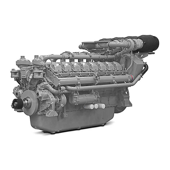
SEBU8604 Product Information Section Model Views Model Views i03754000 Model View Illustrations 4016-61TRG The following model views show typical features of the engine. Due to individual applications, engines may appear different from the Illustrations. Note: Only serviced components are identified on the following Illustrations. - Page 14 SEBU8604 Product Information Section Model Views g02029553 Illustration 10 Left side view of engine (1) Engine crankcase breather (A Bank) (5) Engine crankcase breather (B Bank) (9) Oil level gauge (Dipstick) (2) Thermostat housing (A Bank) (6) Air shutoff valve (B Bank) (10) Oil filler (3) Electronic governor actuator (7) 3x Oil filters (B Bank)
-
Page 15: Engine Description
Bank A cylinders are on the right hand side of the engine. Bank B cylinders are on the left hand side of The 4016-61 TRG engine model is designed for the engine. To determine the left and right sides of power generation. -
Page 16: Engine Cooling And Lubrication
Refer to this Operation and Maintenance Manual, “Maintenance Interval Schedule” for more g01210841 Illustration 12 information on maintenance items. 4016-61 TRG engine model (A) Bank (B) Bank (X) Inlet valves (Y) Exhaust valves Table 1 4016-61 Engine Specifications... -
Page 17: Product Identification Information
Plate Locations and Film TAG1 TAG2 Locations TAG3 TWG2 Engine Identification TWG3 Perkins engines are identified by an engine serial TRG1 number. TEG2 A typical example of an engine serial number is TEG3 DGB R**** U00001M. TRG2 Made in Stafford... -
Page 18: Serial Number Plate
SEBU8604 Product Information Section Product Identification Information Serial Number Plate g02029586 Illustration 14 g01266904 Illustration 13 Typical example Serial number plate The serial number plate (1) on a engine is located on the left side of the cylinder block (bank B). The engine serial number plate contains the following information: •... -
Page 19: Operation Section
SEBU8604 Operation Section Lifting and Storage Operation Section Lifting and Storage i03880885 Engine Lifting NOTICE Never bend the eyebolts and the brackets. Only load the eyebolts and the brackets under tension. Remem- ber that the capacity of an eyebolt is less as the angle between the supporting members and the object be- comes less than 90 degrees. - Page 20 fixtures obsolete. If alterations are made, ensure that correct lifting devices are provided. Consult your Perkins dealer or your Perkins distributor for information regarding fixtures for correct engine lifting. g02130795...
-
Page 21: Engine Storage
SEBU8604 Operation Section Lifting and Storage i03781209 Engine Storage Refer to Perkins Engine Company Limited, Stafford, ST16 3UB for information on engine storage. There are three different levels of engine storage. Level “A, B and C”. Level “A ” Level “A” will give protection for 12 months for diesel engines and for gas engines. -
Page 22: Features And Controls
SEBU8604 Operation Section Features and Controls Features and Controls i03882309 Monitoring System The engine is equipped with sensors or switches to monitor the following parameters: • Coolant temperature (Switch) • Oil pressure (Switch) • Intake manifold boost pressure (Sensor) • Exhaust temperature Sensors •... -
Page 23: Coolant Temperature Sensor
SEBU8604 Operation Section Features and Controls The Illustrations show the typical locations of the The boost pressure sensor (3) measures the sensors on the engine. Specific engines may appear pressure in the inlet air manifold. A signal is sent to different from the illustrations due to differences in the ECU (1). -
Page 24: Engine Oil Pressure Switch
SEBU8604 Operation Section Features and Controls Engine Oil Pressure Switch g02041294 Illustration 21 Engine oil pressure sensor (4) Oil pressure sensor (A Bank) (9) Oil pressure sensor (B Bank) An oil pressure sensor is installed on both side of the engine. The engine oil pressure sensors are mounted in the main oil gallery. -
Page 25: Speed/Overspeed Sensors
SEBU8604 Operation Section Features and Controls The speed sensor (7) should be serviced at the required maintenance interval. Refer to the Operation and Maintenance Manual, “Speed Sensor, Clean/Inspect”. Failure of the Speed Sensor If the ECU (1) does not receive a signal from the speed sensor (4), the engine cannot run. -
Page 26: Starting The Engine
SEBU8604 Operation Section Engine Starting Engine Starting a. Ensure that the governor stays in the STOP position by disconnecting the speed pickup connector on the governor control. i03873029 b. Turn the keyswitch to the START position. Before Starting Engine Hold the keyswitch in this position until the oil pressure gauge indicates 100 kPa (14.5040 psi). -
Page 27: Cold Weather Starting
SEBU8604 Operation Section Engine Starting i02415223 Cold Weather Starting Do not use aerosol types of starting aids such as ether. Such use could result in an explosion and personal injury. Startability will be improved at temperatures below +10 °C (+50 °F) from the use of a jacket water heater or extra battery capacity. -
Page 28: Engine Operation
Fuel Conservation Practices i02415225 Engine Operation The efficiency of the engine can affect the fuel economy. Perkins design and technology in manufacturing provides maximum fuel efficiency in all applications. Follow the recommended procedures Correct operation and maintenance are key factors... -
Page 29: Engine Stopping
SEBU8604 Operation Section Engine Stopping Engine Stopping i02415231 After Stopping Engine i02415227 Stopping the Engine Note: Before you check the engine oil, do not operate the engine for at least 10 minutes in order to allow the engine oil to return to the oil pan. Note: Individual applications will have different •... -
Page 30: Maintenance Section
SEBU8604 Maintenance Section Refill Capacities Maintenance Section Fuel System Refer to the OEM specifications for additional information on the capacity of the Fuel System. Refill Capacities Table 7 Engine i03754119 Refill Capacities Refill Capacities Compartment or System 4016 Minimum Capacity of Fuel 22500 L (4949 Imp gal) Tank Lubrication System... -
Page 31: Glycol
Property Maximum Limit • Cavitation of the water pump Chloride (Cl) 40 mg/L For optimum performance, Perkins recommends a Sulfate (SO 100 mg/L 1:1 mixture of a water/glycol solution. Total Hardness 170 mg/L Note: Use a mixture that will provide protection... -
Page 32: Elc Cooling System Maintenance
Coolant Recommendations ELC is available in a 1:1 premixed cooling solution with distilled water. The Premixed ELC provides The following two coolants are used in Perkins diesel freeze protection to −36 °C (−33 °F). The Premixed engines: ELC is recommended for the initial fill of the cooling system. -
Page 33: Elc Cooling System Cleaning
SEBU8604 Maintenance Section Refill Capacities 4. Use Perkins cleaner to clean the system. Follow the instruction on the label. NOTICE Do not use a conventional coolant to top-off a cooling 5. Drain the cleaner into a suitable container. Flush system that is filled with Extended Life Coolant (ELC). - Page 34 Use the equation that is in Table 13 to determine the container according to local regulations. Then, fill amount of Perkins SCA that is required when the the cooling system with premixed ELC. This should cooling system is initially filled.
-
Page 35: Fuel Recommendations
“ISO 12156 - 1” Coolant Cetane number Perkins cooling system cleaners are designed This indicates the properties of ignition of the fuel. to clean the cooling system of harmful scale Fuel with a low cetane number can be the root and corrosion. - Page 36 “ASTM D975 - 91 Class 1D” Table 17 “JP7, Mil T38219” Perkins Specifications for Distillate Diesel Fuel Specifications Requirements ASTM Test “NATO F63” Aromatics 35% maximum “D1319”...
- Page 37 (Table 17, contd) NOTICE Copper Strip No. 3 maximum “D130” Operating with fuels that do not meet the Perkins rec- Corrosion ommendations can cause the following effects: Start- 10% at 282 °C ing difficulty, poor combustion, deposits in the fuel in- (540 °F)
-
Page 38: Engine Oil
API CH-4 oils may be used in Perkins engines that use API CG-4 and API • API CG-4 CF-4 oils. API CH-4 oils will generally exceed the performance of API CG-4 oils in the following criteria: •... - Page 39 SEBU8604 Maintenance Section Refill Capacities Some commercial oils that meet the API classifications may require reduced oil change NOTICE intervals. To determine the oil change interval, closely Operating Direct Injection (DI) diesel engines with fuel monitor the condition of the oil and perform a wear sulphur levels over 0.5 percent will require shortened metal analysis.
-
Page 40: Aftermarket Oil Additives
finished oils consist of base oils and of commercial Re-refined base stock oils are acceptable for additive packages. These additive packages are use in Perkins engines if these oils meet the blended into the base oils at precise percentages in performance requirements that are specified by order to help provide finished oils with performance... - Page 41 SEBU8604 Maintenance Section Refill Capacities The oil analysis is a diagnostic tool that is used to determine oil performance and component wear rates. Contamination can be identified and measured through the use of the oil analysis. The oil analysis includes the following tests: •...
-
Page 42: Maintenance Interval Schedule
SEBU8604 Maintenance Section Maintenance Interval Schedule Engine Protective Devices - Check ...... 60 i03786359 Governor Actuator - Check ........68 Maintenance Interval Schedule Speed Sensor - Clean/Inspect ......72 Every 7500 Service Hours When Required Alternator - Inspect ..........44 Engine Oil Pump - Inspect ........ -
Page 43: Every 500 Service Hours Or 1 Year Actuator Control Linkage - Lubricate
SEBU8604 Maintenance Section Actuator Control Linkage - Lubricate i02471679 i03895079 Actuator Control Linkage - Aftercooler Core - Clean/Test Lubricate Personal injury can result from air pressure. Personal injury can result without following prop- er procedure. When using pressure air, wear a pro- tective face shield and protective clothing. -
Page 44: Initial 100 Service Hours Alternator Pulley - Check
Personal injury can result from air pressure. Personal injury can result without following prop- er procedure. When using pressure air, wear a pro- Perkins recommends a scheduled inspection of tective face shield and protective clothing. the alternator. Inspect the alternator for loose connections and correct battery charging. -
Page 45: Battery - Replace
SEBU8604 Maintenance Section Battery - Replace 2. Turn off any battery chargers. Disconnect any battery chargers. 3. The NEGATIVE “-” cable connects the NEGATIVE “-” battery terminal to the NEGATIVE “-” terminal on the starting motor. Disconnect the cable from the NEGATIVE “-”... -
Page 46: Battery Or Battery Cable - Disconnect
SEBU8604 Maintenance Section Battery or Battery Cable - Disconnect 2. Check the condition of the electrolyte with a 7. Proceed with necessary system repairs. suitable battery tester. 8. In order to connect the battery, connect the 3. Install the caps. positive connection before the negative connector. -
Page 47: Belts - Inspect/Adjust/Replace
SEBU8604 Maintenance Section Belts - Inspect/Adjust/Replace g01239310 Illustration 33 4. Apply 15.6 N (3.5 lb) of pressure at point (X). The total deflection should not exceed 1.5 mm (0.06 inch). g01239580 Illustration 34 Replace the belt if the total deflection exceeds Typical example 1.5 mm (0.06 inch). - Page 48 SEBU8604 Maintenance Section Belts - Inspect/Adjust/Replace 2. Loosen the fasteners for the air pipes (not shown). 3. Remove the guards (not shown). g01239588 Illustration 36 2. Loosen the locknut (4). g02025020 Illustration 35 3. Rotate the rod (3) in order to achieve the correct tension of belts (1).
-
Page 49: Every 12 000 Service Hours Or 6 Years Cooling System Coolant (Elc) - Change
SEBU8604 Maintenance Section Cooling System Coolant (ELC) - Change Drain 2. Rotate the rod (3) in order to achieve the correct tension of belts (1). The total deflection should not exceed 12.5 mm (0.5 inch). 3. Tighten the locknut (4) to a torque of 120 N·m Pressurized System: Hot coolant can cause seri- (88.5 lb ft). - Page 50 The full distillation Do not fill the cooling system faster than 5 L procedure is the only method acceptable by Perkins to (1.3 US gal) per minute to avoid air locks. reclaim the coolant.
-
Page 51: Cooling System Coolant - Change
SEBU8604 Maintenance Section Cooling System Coolant - Change 2. Fill the cooling system with Extended Life i03837649 Coolant (ELC). Refer to the Operation and Cooling System Coolant - Maintenance Manual, “Fluid Recommendations” Change topic (Maintenance Section) for more information on cooling system specifications. (Inhibitor) Note: Open the air vent (4) in order to allow air to be removed from the system. - Page 52 3. Open the drain cock or remove the drain plug on mandates. When you recycle used engine coolant for the radiator. reuse in engine cooling systems, the full distillation procedure is the only method acceptable by Perkins Engines Company LTD to reclaim the coolant.
-
Page 53: Cooling System Coolant Level - Check
SEBU8604 Maintenance Section Cooling System Coolant Level - Check Flush Note: Open the air vent (4) in order to allow air to be removed from the system. Fill the cooling system 1. Flush the cooling system with clean water in order until coolant free of air flows from the vent . -
Page 54: Engine - Clean
SEBU8604 Maintenance Section Driven Equipment - Check • Other maintenance recommendations Perform any maintenance for the driven equipment which is recommended by the OEM. i02415247 Engine - Clean Personal injury or death can result from high volt- g01211179 age. Illustration 47 1. -
Page 55: Engine Air Cleaner Element - Replace
SEBU8604 Maintenance Section Engine Air Cleaner Element - Replace 3. Install a new element (2) into the housing (1). i03781216 Align the cover (3) to the housing (1). Secure the Engine Air Cleaner Element - clips (3). Replace i02415251 Engine Air Cleaner Service Indicator - Inspect NOTICE Never run the engine without an air cleaner element... -
Page 56: Engine Crankcase Breather - Clean
SEBU8604 Maintenance Section Engine Crankcase Breather - Clean Service Indicator Reset g01242328 Illustration 52 Once the service indicator has been triggered and when the air filter element has been replaced, the service indicator must be reset. In order to reset the service indicator (1), press the button (2). -
Page 57: Engine Oil Filter (Auxiliary) - Change
SEBU8604 Maintenance Section Engine Oil Filter (Auxiliary) - Change • Loose bolts The changeover valve (1) has three positions. • • Deterioration of the isolators (A) The oil flow is to both oil filters. • Ensure that the mounting bolts are tightened to the (B) The oil flow is to the left hand oil filter. -
Page 58: Engine Oil Sample - Obtain
A trend can be established by analyzing the results of the oil sampling. Each individual operator can develop a service program for the engine. Note: Perkins Engines Stafford must agree to the g01165836 Illustration 56 maintenance schedule. (Y) “Min” mark. (X) “Max” mark. -
Page 59: Drain The Engine Lubricating Oil
Strap Wrench NOTICE Keep all parts clean from contaminants. NOTICE Perkins oil filters are manufactured to Perkins Engine Contaminants may cause rapid wear and shortened Company LTD specifications. Use of an oil filter that is component life. not recommended by Perkins Engine Company LTD could result in severe damage to the engine. -
Page 60: Fill The Oil Pan
SEBU8604 Maintenance Section Engine Protective Devices - Check 3. Start the engine and run the engine for two minutes. Perform this procedure in order to ensure that the lubrication system has oil and that the oil filters are filled. Inspect the oil filters for oil leaks. 4. -
Page 61: Engine Valve Lash - Inspect/Adjust
Rock Adjust Valves. maintenance. Refer to the Service Manual or your au- A1 & A8 thorized Perkins dealer or your Perkins distributor for the complete valve lash adjustment procedure. B1 & B8 A3 & A6 Operation of Perkins engines with incorrect valve lash can reduce engine efficiency, and also reduce engine... - Page 62 SEBU8604 Maintenance Section Engine Valve Lash - Inspect/Adjust g01241941 Illustration 61 4016 Engine g01241584 Illustration 63 6. Loosen the locknut (7) on the inlet valve bridge. 7. In order to equalize the bridge, turn the adjuster (6) until the fixed pad on the valve bridge (5) and the adjuster is in contact with the valve.
-
Page 63: Fan Drive Pulley - Check
SEBU8604 Maintenance Section Fan Drive Pulley - Check a. Loosen the locknut (9) on the rocker arm of the inlet valve. b. Use Tooling (B) in order to set the valve lash. c. Turn the adjuster (8) until the pad on the rocker arm is in contact with Tooling (B). -
Page 64: Fuel System - Prime
SEBU8604 Maintenance Section Fuel Injector - Inspect/Adjust i03784609 Fuel Injector - Inspect/Adjust Inspect the Fuel Injectors Refer to System Operation,Testing and Adjusting , KENR9224, “Fuel Injector Adjustment” for information on inspection of the fuel injectors. i02415266 Fuel System - Prime If air enters the fuel system, the air must be purged from the fuel system before the engine can be started. -
Page 65: Fuel System Filter - Replace
SEBU8604 Maintenance Section Fuel System Filter - Replace 8. Operate the handle (4) until fuel that is free of air 2. Place a suitable container under the fuel filter in flows from the connection (5). order to catch any fuel that might spill. 9. -
Page 66: Fuel System Primary Filter/Water Separator - Drain
SEBU8604 Maintenance Section Fuel System Primary Filter/Water Separator - Drain i03880440 i02335436 Fuel System Primary Fuel Tank Water and Sediment Filter/Water Separator - Drain - Drain NOTICE Care must be taken to ensure that fluids are contained during performance of inspection, maintenance, test- Fuel leaked or spilled onto hot surfaces or elec- ing, adjusting, and repair of the product. -
Page 67: Fuel Transfer Pump (Lift Pump) - Inspect
SEBU8604 Maintenance Section Fuel Transfer Pump (Lift Pump) - Inspect Some fuel tanks use supply pipes that allow water and sediment to settle below the end of the fuel supply pipe. Some fuel tanks use supply lines that take fuel directly from the bottom of the tank. If the engine is equipped with this system, regular maintenance of the fuel system filter is important. -
Page 68: Hoses And Clamps - Inspect/Replace
The coolant system and the hoses for the coolant system are not usually supplied by Perkins. The following text describes a typical method of replacing If you inspect the engine in operation, always use coolant hoses. -
Page 69: Overhaul (Major)
This measurement can be used to predict when occurs. Also, the increased use of lube oil will dilute a cylinder head requires replacement. the wear metals. Monitor the engine as the engine accumulates service hours. Consult Perkins Engines Stafford about scheduling a major overhaul. -
Page 70: Top End Overhaul Information
SEBU8604 Maintenance Section Radiator - Clean Note: Generally, cylinder heads wear out at different After 4000 hours running, the valve seat wear on rates. In some cases, servicing the cylinder heads at the inlet is 0.65 mm (0.026 inch) and the exhaust is different times may be the most economic decision. -
Page 71: Severe Service Application - Check
Operating outside the intended application Refer to the standards for the engine or consult your Incorrect Maintenance Procedures Perkins dealer or your Perkins distributor in order to determine if the engine is operating within the defined • Extending the maintenance intervals parameters. -
Page 72: Speed Sensor - Clean/Inspect
SEBU8604 Maintenance Section Speed Sensor - Clean/Inspect 4. Use a soft, dry cloth in order to clean any debris i03896257 from the sensor (2). Speed Sensor - Clean/Inspect (Engine Speed Sensor and Note: Do not use a wire brush in order to clean the sensor. -
Page 73: Starting Motor - Inspect
SEBU8604 Maintenance Section Starting Motor - Inspect 7. Unscrew the sensor (2) by half of one full turn in order to obtain a clearance (X) of 0.5 to 0.8 mm (0.02 to 0.03 inch). 8. Tighten the locknut (1). Do not allow the sensor (2) to rotate. -
Page 74: Walk-Around Inspection
A walk-around inspection should only take a few options regarding removal, installation, repair and minutes. When the time is taken to perform these replacement, consult a Perkins dealer or a Perkins checks, costly repairs and accidents can be avoided. distributor. -
Page 75: Water Pump - Inspect
Excessive coolant leakage may indicate the need to replace a water pump. Refer to Operation and Maintenance Manual, “Water Pump - Inspect” for more information. If necessary, consult your Perkins dealer or your Perkins distributor. • Inspect the lubrication system for leaks at the front crankshaft seal, the rear crankshaft seal, the oil pan, the oil filters and the rocker cover. -
Page 76: Warranty Section
Emissions Warranty. Consult your authorized Perkins dealer or your authorized Perkins distributor in order to determine if your engine is emissions certified and if your engine is subject to an Emissions Warranty. -
Page 77: Index
SEBU8604 Index Section Index Engine Air Cleaner Service Indicator - Inspect..55 Service Indicator Check ........55 Service Indicator Reset........56 Actuator Control Linkage - Lubricate ..... 43 After Stopping Engine..........29 Engine Crankcase Breather - Clean...... 56 Aftercooler Core - Clean/Test ........ 43 Engine Description .......... - Page 78 SEBU8604 Index Section Foreword ..............4 California Proposition 65 Warning ....... 4 Literature Information........... 4 Operation Section..........19 Maintenance ............4 Overhaul (Major)............ 69 Maintenance Intervals.......... 4 Major Overhaul Information ....... 69 Scheduling a Major Overhaul......69 Operation ............. 4 Overhaul (Top End) ..........
- Page 79 SEBU8604 Index Section Turbocharger - Inspect .......... 74 Walk-Around Inspection ........74 Warranty Information ..........76 Warranty Section ........... 76 Water Pump - Inspect..........75 Welding on Engines with Electronic Controls ..12...
- Page 80 SEBU8604 Index Section...
- Page 81 Product and Dealer Information Note: For product identification plate locations, see the section “Product Identification Information” in the Operation and Maintenance Manual. Delivery Date: Product Information Model: Product Identification Number: Engine Serial Number: Transmission Serial Number: Generator Serial Number: Attachment Serial Numbers: Attachment Information: Customer Equipment Number: Dealer Equipment Number:...
- Page 82 ©2010 Perkins Engines Company Limited Printed in U.K. All Rights Reserved...
Need help?
Do you have a question about the 4016-61 TRG and is the answer not in the manual?
Questions and answers