
Related Manuals for Portwell WADE-8022


Summary of Contents for Portwell WADE-8022
- Page 1 WADE-8022 Mini-ITX Board User's Manual Version 1.0 Copyright © Portwell, Inc., 2014. All rights reserved. All other brand names are registered trademarks of their respective owners.
-
Page 2: Table Of Contents
Preface Table of Contents How to Use This Manual Chapter 1 System Overview.......................1-1 1.1 Introduction ....................... 1-1 1.2 Check List......................1-2 1.3 Product Specification..................1-2 1.3.1 Mechanical Drawing................1-4 1.4 System Architecture..................1-6 Chapter 2 Hardware Configuration ...................2-1 2.1 Jumper Setting ....................2-1 2.2 Connector Allocation.................. -
Page 3: How To Use This Manual
Preface How to Use This Manual The manual describes how to configure your WADE-8022 system board to meet various operating requirements. It is divided into five chapters, with each chapter addressing a basic concept and operation of Mini-ITX Board. Chapter 1: System Overview. Presents what you have in the box and give you an overview of the product specifications and basic system architecture for this series model of Mini-ITX Board. -
Page 4: Chapter 1 System Overview
System Overview Chapter 1 System Overview 1.1 Introduction Portwell Inc., a world-leading innovator in the Industrial PC (IPC) market and a member of the Intel Embedded and Communications Alliance (Intel ECA), ® ® announced today the Portwell WADE-8022 adopting the Mini-ITX form factor. The... -
Page 5: Check List
Support Ten USB (Universal Serial Bus) ports, four USB 3.0 ports on rear I/O and six USB 2.0 ports on board header for internal devices Audio Interface Line-Out Audio Jack on Rear I/O, Mic-In, Line-In on board header Real Time Clock/Calendar (RTC) Support Y2K Real Time Clock/Calendar WADE-8022 User’s Manual... - Page 6 4.82 V/ 970 mA Configuration CPU Type Intel Celeron CPU 2000E @ 2.20GHz L3: 2Mbytes ® SBC BIOS Portwell, Inc. WADE-8022 TEST BIOS ( 40820T00 ) EC Version 40717T00 ( 07/17/2014 ) Memory WARIS DDR3L SO-DIMM 1600 1.35V/8GB*1 (Skhynix H5TC4G83AFR ) VGA Card...
-
Page 7: 1.3.1 Mechanical Drawing
System Overview Operating Temperature 0 °C ~ 60 °C Storage temperature -20 ~ 80 °C Relative Humidity 0% ~ 90%, non-condensing 1.3.1 Mechanical Drawing WADE-8022 User’s Manual... - Page 8 System Overview WADE-8022 User’s Manual...
-
Page 9: 1.4 System Architecture
System Overview 1.4 System Architecture All of details operating relations are shown in WADE-8022 System Block Diagram. WADE-8022 System Block Diagram WADE-8022 User’s Manual... -
Page 10: Chapter 2 Hardware Configuration
Hardware Configuration Chapter 2 Hardware Configuration This chapter gives the definitions and shows the positions of jumpers, headers and connectors. All of the configuration jumpers on WADE-8022 are in the proper position. Jumper Setting WADE-8022 User’s Manual... - Page 11 Hardware Configuration WADE-8022 User’s Manual...
- Page 12 JP4: WDT Function Select PIN No. Signal Description 1-2 short WDT Function enable (Default) 1-2 open WDT Function disable JP5: ATX / AT Mode Select PIN No. Signal Description 1-2 short ATX emulation AT mode 1-2 open ATX mode WADE-8022 User’s Manual...
- Page 13 Signal Description Ground Ground +12V +12V J11: 8Bit GPIO Connector PIN No. Signal Description PIN No. Signal Description LPC_GPJ0 LPC_GPE0 LPC_GPJ1 LPC_GPE7 LPC_GPJ2 LPC_GPC0 LPC_GPJ3 LPC_GPG0 J13: LVDS Power Connector PIN No. Signal Description BL_BRIGHT +12V Ground BL_ENABLE WADE-8022 User’s Manual...
- Page 14 J15: Dual channel LVDS Connector PIN No. Signal Description PIN No. Signal Description LCD1DO0+ LCD1DO0- LCD1DO1+ LCD1DO1- LCD1DO2+ LCD1DO2- LCD1DO3+ LCD1DO3- LCD1CLK+ LCD1CLK- LCLK1 LDATA1 Ground Ground LCD2DO0+ LCD2DO0- LCD2DO1+ LCD2DO1- LCD2DO2+ LCD2DO2- LCD2DO3+ LCD2DO3- LCD2CLK+ LCD2CLK- Ground Ground WADE-8022 User’s Manual...
- Page 15 Ready) GND (Ground) DSR (Data Set Ready) RTS (Request to Send) CTS (Clear to Send) RI (Ring Indicator) J20: Clear CMOS PIN No. Signal Description Normal Clear CMOS J22/J26: SATA Power Connector Pin No. Signal Description +12V WADE-8022 User’s Manual...
- Page 16 Signal Description 5V Dual 5V Dual USB- USB- USB+ USB+ Ground Ground J27: SMBus Connector PIN No. Signal Description SMBus_CLK Ground SMBus_DAT J32: SYSTEM FAN Power Connector PIN No. Signal Description Ground Fan speed control Fan on/off output WADE-8022 User’s Manual...
- Page 17 PIN No. Signal Description Ground +12V Fan on/off output Fan Speed control J39:PS/2 Keyboard/Mouse Pin Header PIN No. Signal Description PIN No. Signal Description Mouse Data Keyboard Data Ground Ground PS2 Power PS2 Power Mouse Clock Keyboard Clock WADE-8022 User’s Manual...
- Page 18 J41: SPI Bus Select Header PIN No. Signal Description 1-3, 2-4, 7-9, 8-10 CFEX 3-5, 4-6, 9-11, 10-12 Normal SW1: LVDS GPIO Switch Select ON : 0 ; OFF : 1 Default : 0001 Pin No. Signal Description WADE-8022 User’s Manual...
-
Page 19: Connector Allocation
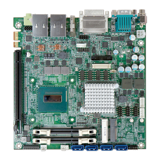
Only Support Mini PCIe Mini PCIe Slot Only Support mSATA J30、J31 SO-DIMM Slot Only Support DDR3L Memory System FAN Power Connector J33、J34、J35、 SATA Connector(6Gb/s) Front Panel System Connector CPU FAN Power Connector PS/2 Keyboard/Mouse Pin Header WADE-8022 User’s Manual 2-10... - Page 20 Hardware Configuration CFEX Card slot SPI Select HEADER WADE-8022 User’s Manual 2-11...
-
Page 21: Chapter 3 System Installation
WADE-8022 can support 4th Generation Mobile Celeron/Core Haswell i3/i5/i7 Processors (BGA Type) by optional. Main Memory WADE-8022 provide 2 x 204 pin DIMM sockets (Dual Channel) which supports Dual channel 1333 DDR3L-SO-DIMM (1.35V) Non-ECC (Error Checking and Correcting), non-register functions as main memory. The maximum memory can be up to 16GB. -
Page 22: Installing The Mini-Itx Board Computer
Step 1: Check all jumpers setting on proper position Step 2: Install and configure CPU and memory module on right position Step 3: Place WADE-8022 into the dedicated position in the system Step 4: Attach cables to existing peripheral devices and secure it WARNING Please ensure that SBC is properly inserted and fixed by mechanism. -
Page 23: Intel ® Integrated Graphics Controller
1200 resolution) from QM87 PCH display output. Processor integrated 3D graphics Media Accelerator . Supports DX11.1, OpenGL 3.1, MPEG-2, Shader Model 4.0. WADE-8022 can support triple display output. Drivers Support Please find the Graphic drivers in the WADE-8022 CD-title. Drivers support Win7. 3.3.3 Gigabit Ethernet Controller... -
Page 24: Ec Wdt
1; static int OBF_Check () unsigned char OBF_status; delay(2); OBF_status = inportb (EC_CMD); } while (!(OBF_status & 0x01)); return 1; static void Write_EC (unsigned char index, unsigned char data) IBF_Check (); outportb (EC_CMD, EC_CMD_WRITE); IBF_Check (); WADE-8022 User’s Manual... - Page 25 /* 0x01 is second mode */ /* 0x03 is minute mode */ Write_EC (WDT_MODE, 0x01); int main () int i; EC_WDT_Trigger (); for (i = 0; i < 5; i++) printf ("Reset counter ....%d\n", 5 - i); delay (1000); return 0; WADE-8022 User’s Manual...
-
Page 26: Ec Gpio
(EC_CMD, EC_CMD_READ); sleep(1); outportb (EC_DATA, address); sleep(1); data = inportb (EC_DATA); return data; int main () unsigned char d2; printf("\n\n"); printf("WADE-8079 GPIO TEST Program v1.0\n"); printf("Please short the following pins with 2.54mm-pitched jumper on JP8\n"); WADE-8022 User’s Manual... - Page 27 Write_EC (GPIO_DATA, 0xFF); printf("Write_EC data 0xFF\n"); sleep (2); /* Set GPIO Port In/Out mode */ Write_EC (GPIO_DIR, 0x00); sleep (2); printf("Write_EC mode 0x00\n"); /* Set Low or High */ Write_EC (GPIO_DATA, 0x00); printf("Write_EC data 0x00\n"); sleep (2); return 0; WADE-8022 User’s Manual...
-
Page 28: Chapter 4 Bios Setup Information
Chapter 4 BIOS Setup Information WADE-8022 uses AMI BIOS structure stored in Flash ROM. These BIOS has a built-in Setup program that allows users to modify the basic system configuration easily. This type of information is stored in CMOS RAM so that it is retained during power-off periods. -
Page 29: Main
These items show the firmware and memory specifications of your system. Read only. System Date The date format is <Day>, <Month> <Date> <Year>. Use [+] or [-] to configure system Date. System Time The time format is <Hour> <Minute> <Second>. Use [+] or [-] to configure system Time. WADE-8022 User’s Manual... -
Page 30: Configutation
BIOS Setup Information Configutation Use this menu to set up the items of special enhanced features. CPU Configuration CPU Configuration Parameters WADE-8022 User’s Manual... - Page 31 Choices: Disabled, Enabled. CPU C6 Report (CPU C states Enabled) Enable/Disable CPU C6 report to OS Choices: Disabled, Enabled. CPU C7 Report (CPU C states Enabled) Enable/Disable CPU C7 report to OS Choices: Disabled, CPU C7, CPU C7s. WADE-8022 User’s Manual...
- Page 32 Choices: Disabled, Enabled. Port 80h Redirection Control where the Port 80h cycles are sent [LPC BUS] Forward I/O Port 80 to LPC [PCIE BUS] Forward I/O Port 80 to PCIE Subtractive device Choices: LPC BUS, PCIE BUS. WADE-8022 User’s Manual...
-
Page 33: Intel Amt
This option just controls the BIOS extension execution. If enabled, this requires additional firmware in the SPI device Choices: Disabled, Enabled. Un-configure ME OEMFlag Bit 15: Un-configure ME without password. Choices: Disabled, Enabled. Disable ME Set ME to Soft Temporary Disabled. Choices: Disabled, Enabled. WADE-8022 User’s Manual... - Page 34 BIOS Setup Information Memory Configuration Memory Configuration Parameters (Read Only) LAN Configuration Configuration On Board LAN device. WADE-8022 User’s Manual...
- Page 35 Choices: Enabled, Disabled. Wake on LAN I210 Enable or disable integrated LAN to wake the system. (The Wake On LAN cannot be disabled if ME is on at Sx state.) Choices: Enabled, Disabled. Graphic Configuration Configuration Graphics Settings WADE-8022 User’s Manual...
- Page 36 Secondary boot display will appear based on your selection. VGA modes will be supported only on primary display. Choices: VBIOS Default, VGA, DP, LVDS, DVI HDMI. Secondary IGFX Boot Display Select Secondary IFGX Boot Display Device. Choices: Disabled, DP, LVDS, DVI, HDMI. WADE-8022 User’s Manual...
- Page 37 Choices: Auto, 128 Bytes, 256 Bytes, 512 Bytes, 1024 Bytes, 2048 Bytes, 4096 Bytes. Maximum Read Request Set Maximum Read Request size of PCI Express Device or allow System BIOS to select the value. Choices: Auto, 128 Bytes, 256 Bytes, 512 Bytes, 1024 Bytes, 2048 Bytes, 4096 Bytes. WADE-8022 User’s Manual 4-10...
- Page 38 Control ASPM support for the PEG Device. This has no effect if PEG is not the currently active device. Choices: Disabled, Auto, ASPM L0s, ASPM L1, ASPM L0sL1. PEG2 – Gen X Configure PEG2 B0:D1:F2 Gen1-Gen3 Choices: Auto, Gen1, Gen2, Gen3 WADE-8022 User’s Manual 4-11...
- Page 39 Control ASPM support for the PEG Device. This has no effect if PEG is not the currently active device. Choices: Disabled, Auto, ASPM L0s, ASPM L1, ASPM L0sL1. Enable PEG To enable or disable the PEG Choices: Disabled, Enabled, Auto. PCH PCI Express Configuration PCH PCI Express Configuration settings WADE-8022 User’s Manual 4-12...
- Page 40 PCI Express Root Port 1-5, Port8 Control the PCI Express Root Port Choices: Enabled, Disabled. ASPM PCI Express Active State Power Management settings Choices: Disabled, L0s, L1, L0sL1, Auto PCIe Speed Select PCI Express port speed. Choices: Auto, Gen1, Gen2. WADE-8022 User’s Manual 4-13...
-
Page 41: Sata Configuration
BIOS Setup Information SATA Configuration SATA Device Options Settings SATA Controller(s) Enable or disable SATA Device. Choices: Enabled, Disabled. WADE-8022 User’s Manual 4-14... - Page 42 Note: Requires hardware support. Choices: Disabled, Enabled. External SATA External SATA Support Choices: Disabled, Enabled. SATA Device Type Identify the SATA Port is connected to Solid State Drive or Hard Disk Drive. Choices: Hard Disk Drive, Solid State Drive. WADE-8022 User’s Manual 4-15...
- Page 43 This is a workaround for OSes without EHCI hand-off support. The EHCI ownership change should claim by EHCI driver. Choices: Disabled, Enabled. USB Mass Storage Driver Support Enable/Disable USN Mass Storage Driver Support. Choices: Disabled, Enabled. WADE-8022 User’s Manual 4-16...
- Page 44 BIOS Setup Information PCH USB Configuration PCH USB Configuration settings USB Port #0-11 Disable USB Port Choices: Disabled, Enabled. WADE-8022 User’s Manual 4-17...
- Page 45 Choices: Always Off, Always On, Last State. Wake system with Fixed Time Enable or disable system wake on alarm event. When enabled, System will wake on the hr::min::sec specified. Choices: Disabled, Enabled. WADE-8022 User’s Manual 4-18...
-
Page 46: Tpm Configuration
Select 0-23 for example enter 3 for 3am and 15 for 3pm. Choices: 0-23. Wake up minute Choices: 0-59. Wake up second Choices: 0-59. Wake up Ring Enable or Disable Wake on Ring form OS. Choices: Disabled, Enabled. TPM Configuration Trusted Computing Settings WADE-8022 User’s Manual 4-19... - Page 47 Timer Unit Select Timer count unit of WDT. Choices: Second, Minute. Timer value Select WDT Timer value Seconds Range: 10 to 255 Choices: 10-255. Serial Port 1-6 Enable or Disable Serial Port 1-6 (COM) Choices: Disabled, Enabled. WADE-8022 User’s Manual 4-20...
- Page 48 Choices: Disabled, Thermal Cruise Mode. Smart Fan Start Temperature Set Temperature for Start CPU Smart Fan (40 to 105) Choices: 40-105 Smart Fan Full Speed Temperature Set Temperature for Smart Fan Full Speed (40 to 105) Choices: 40-105 WADE-8022 User’s Manual 4-21...
- Page 49 Serial Port Console Redirection Serial Port Console Redirection Serial Port 1 (Disabled) Console Redirection Console Redirection Enable or Disable Choices: Disabled, Enabled. Serial Port 2 (Disabled) Console Redirection Console Redirection Enable or Disable Choices: Disabled, Enabled. WADE-8022 User’s Manual 4-22...
-
Page 50: Boot
Set display mode for Option ROM. Choices: Force BIOS, Keep Current. INT19 Trap Response BIOS reaction on INT19 trapping by Option ROM: IMMEDIATE – execute the trap right away; POSTPONED – execute the trap during legacy boot. Choices: Immediate, Postponed. WADE-8022 User’s Manual 4-23... - Page 51 Choices: Disable Link, Enabled. Boot mode select Select boot mode LEGACY/UEFI. Choices: LEGACY, UEFI. Boot Option #1-7 Sets the system boot order Choices: Hard Disk, CD/DVD, USB Hard Disk, USB CD/DVD, USB Key, USB Floppy, Network, Disabled. WADE-8022 User’s Manual 4-24...
-
Page 52: Security
BIOS Setup Information Security Administrator Password Set Setup Administrator Password User Password Set User Password WADE-8022 User’s Manual 4-25... -
Page 53: Save & Exit
Reset the system after saving the changes. Pressing <Enter> on this item asks for confirmation: Save configuration and reset. Discard Changes and Exit Reset system setup without saving any changes. Restore Defaults Restore/Load Default values for all the setup options. WADE-8022 User’s Manual 4-26... -
Page 54: Chapter 5 Troubleshooting
Chapter 5 Troubleshooting This chapter provides a few useful tips to quickly get WADE-8022 running with success. As basic hardware installation has been addressed in Chapter 2, this chapter will primarily focus on system integration issues, in terms of BIOS setting, and OS diagnostics. - Page 55 SATA Mode Selection …….………… [Press enter] SATA Mode…… [IDE/AHCI /RAID Mode] CFEX support The J40 (CF 50pin socket) supports CFEX. (Has SATA signal). mSATA device support The J28 (Mini-PCIe slot) has SATA signal can support mSATA device. WADE-8022 User’s Manual...
-
Page 56: Bios Setting
To make sure that you have a successful start with WADE-8022, it is recommended, when going with the boot-up sequence, to hit “Del” or “Esc” key and enter the BIOS setup menu to tune up a stable BIOS configuration so that you can wake up your system far well. -
Page 57: Faq
Answer: You can simply short 2-3 pins on J20 to clean your password. Question: How to update the BIOS file of the WADE-8022? Answer: 1. Please visit web site of the Portwell download center as below hyperlink and register an account. (The E-Mail box should be an existing Company email address that you check regularly.) - Page 58 Extended BIOS Area 9F00 – 9FFF Unused A000 - AFFF VGA Graphics B000 – B7FF Unused B800 - BFFF VGA Text C000 - CEBF Video ROM CEC0 - EFFF 133K Unused F000 - FFFF System ROM First 64K Extended WADE-8022 User’s Manual...
- Page 59 【Unassigned】 IRQ 10 Video ROM Usable IRQ IRQ 11 Usable IRQ 【Unassigned】 IRQ 12 System ROM IBM Mouse Event IRQ 13 System ROM Coprocessor Error IRQ 14 System ROM Hard Disk Event IRQ 15 Usable IRQ 【Unassigned】 WADE-8022 User’s Manual...
Need help?
Do you have a question about the WADE-8022 and is the answer not in the manual?
Questions and answers