
Related Manuals for Portwell WADE-8011


Summary of Contents for Portwell WADE-8011
- Page 1 WADE-8011 WADE-8012 Mini-ITX Board User's Manual Version 1.4 Copyright © Portwell, Inc., 2013 All rights reserved. All other brand names are registered trademarks of their respective owners.
-
Page 2: Table Of Contents
Preface Table of Contents How to Use This Manual Chapter 1 System Overview.......................1-1 1.1 Introduction ....................... 1-1 1.2 Check List......................1-2 1.3 Product Specification..................1-2 1.3.1 Mechanical Drawing................1-4 1.4 System Architecture..................1-6 Chapter 2 Hardware Configuration ...................2-1 2.1 Jumper Setting ....................2-1 2.2 Connector Allocation.................. -
Page 3: How To Use This Manual
Preface How to Use This Manual The manual describes how to configure your WADE-8011/WADE-8012 system board to meet various operating requirements. It is divided into five chapters, with each chapter addressing a basic concept and operation of Single Host Board. -
Page 4: Chapter 1 System Overview
Chapter 1 System Overview Introduction Portwell Inc., a world-leading innovator in the Industrial PC (IPC) market and a member of the Intel ® Embedded and Communications Alliance (Intel ECA), announced today the Portwell WADE-8011/WADE-8012 adopting the Mini-ITX form factor. The WADE-8011/WADE-8012 of the Intel platform will provide high performance and flexibility for functional expansion, such as Gaming, Kiosk, DS, Medical, Defense, Industrial automation and control applications. -
Page 5: Check List
DDR3 SDRAM up to 16GB, support total 8 USB2.0 ports (4x rear IO/4x on board), VGA / HDMI / DVI-D ,and two Gigabit Ethernet. Check List The WADE-8011/WADE-8012 package should cover the following basic items One WADE-8011/WADE-8012 Mini-ITX Main Board One SATA Cable... - Page 6 170mm(6.69’’) x 170mm(6.69’’) Power Requirements Configuration CPU Type Intel® Core™ i5-2400 CPU 3.10GHz(ES) L3:6M SBC BIOS Portwell, Inc. WADE-8011/WADE-8012 BIOS Rev.: R1.00.E1 Memory Apacer PC3-8500 2GB*1 (ELPIDA J1108BFBG-DJ-E) VGA Card Onboard Intel® HD Graphics Family (Sandy Bridge) VGA Driver Onboard Intel® HD Graphics Family Version 6.14.10.5328 LAN Card Onboard Intel®...
-
Page 7: Mechanical Drawing
1 1 2 . 9 0 10.5 103.35 Restricted component height 85.07 Restricted component height 81.90 15.24 Restricted component height 65.85 64.21 43.35 Keep-out zone Restricted component height : 2 mm 28.35 Restricted component height 1 2 .5 0 4.53 WADE-8011/WADE-8012 User’s Manual... - Page 8 System Overview 1 59 .8 4 1 3 6.98 4 Hole/ 8 Pad_Each side Keep-out zone 4.90 WADE-8011/WADE-8012 User’s Manual...
-
Page 9: System Architecture
System Overview System Architecture All of details operating relations are shown in WADE-8011/WADE-8012 System Block Diagram. WADE-8011/WADE-8012 System Block Diagram WADE-8011/WADE-8012 User’s Manual... -
Page 10: Chapter 2 Hardware Configuration
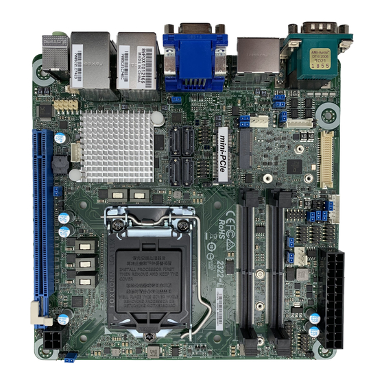
Hardware Configuration This chapter gives the definitions and shows the positions of jumpers, headers and connectors. All of the configuration jumpers on WADE-8011/WADE-8012 are in the proper position. The default settings shipped from factory are marked with an asterisk (♣). - Page 11 Hardware Configuration Figure 2-1 WADE-8011 / WAD-8012 Jumper and Connector Locations WADE-8011/WADE-8012 User’s Manual...
- Page 12 The jumper settings are schematically depicted in this manual as follows: JP1: CMOS Clear Function 1-2 Short Normal Operation 2-3 Short Clear CMOS Contents JP5: WDT Selection Function Short Enable Open Disable JP6: ATX Emulation AT Mode Selection Function Short ATX Emulation AT Mode Open ATX Mode WADE-8011/WADE-8012 User’s Manual...
- Page 13 JP8: COM2 (J2B) Interface Selection Function 5-6, 9-11, 10-12, 15-17, 16-18 Short RS-232 3-4, 7-9, 8-10, 13-15, 14-16, 21-22 Short RS-422 1-2, 7-9, 8-10, 19-20 Short RS-485 JP10: VCC_SA Voltage Selection JP10 Function Short 0.85V Open 0.925V WADE-8011/WADE-8012 User’s Manual...
-
Page 14: Connector Allocation
SATA GEN2 Connector J22/J23 SATA GEN3 Connector PCIe x 16 SLOT J25/J28 DDR3 Socket FAN (SYSTEN FAN) Power Connector FAN (CPU FAN) Power Connector HDMI Connector VRM I2C Debug Connector 3x1 pin header VRM Debug/Program Connector 3x1 pin header WADE-8011/WADE-8012 User’s Manual... - Page 15 SMB_DAT PCIe x1 & USB Connector (J7) Pin No. Signal Description Pin No. Signal Description +3VSBY +3VSBY +1.5V Ground +1.5V +1.5V Ground Ground Ground Ground Ground Ground Ground Ground Ground Ground Ground Ground SUSCLK Ground Ground PCIE_CLK- WADE-8011/WADE-8012 User’s Manual...
- Page 16 J9: TPM Pin Header Pin No. Signal Description Pin No. Signal Description PCKL_TPM LFRAME# SIO2_PLTRST# LAD3 LAD2 VCC3 LAD1 LAD0 SMB_CLK_MAIN SMB_DATA_MAIN 3VSB SERIRQ LPCPD# J10: +12V POWER Connector PIN No. Signal Description Ground Ground +12V +12V WADE-8011/WADE-8012 User’s Manual...
- Page 17 5V Dual USB- USB- USB+ USB+ Ground Ground Key( no pin ) Note: 5V Dual is always available. It's supplied by either 5V VCC power source in normal operation mode or 5V standby power source in standby mode. WADE-8011/WADE-8012 User’s Manual...
- Page 18 All General Purpose I/O ports can only apply to standard TTL ± 5% signal level (0V/5V), and each Fan. Front Panel Pin HDR(J16) Pin No. Signal Description Pin No. Signal Description PWR_LED(+) Speaker(+) PWR_LED(-) LAN1_ACT LAN1_LINK Speaker(-) LAN2_LINK Power On(-) LAN2_ACT Power On(+) HDD_LED(+) Reset (+) HDD_LED(-) Reset (-) WADE-8011/WADE-8012 User’s Manual...
- Page 19 Hardware Configuration J18/J19/J20/J21: SATA GEN2 Connector Pin No. Signal Description Ground Ground Ground J22/J23: SATA GEN3 Connector Pin No. Signal Description Ground Ground Ground WADE-8011/WADE-8012 User’s Manual 2-10...
- Page 20 Hardware Configuration J26: System Fan Connector Pin No. Signal Description Ground Fan speed control Fan on/off output J27: CPU Fan Connector Pin No. Signal Description Ground +12V Fan on/off output Fan Speed control WADE-8011/WADE-8012 User’s Manual 2-11...
-
Page 21: Chapter 3 System Installation
Alignment key Pin1 corner of the CPU Socket LGA-1155 CPU Notch Notch Yellow Triangle Pin1 of the CPU Please remember to locate the alignment keys on the CPU socket of the motherboard and the notches on the CPU. WADE-8011/WADE-8012 User’s Manual... - Page 22 Before install the CPU, please make sure to turn off the power first!! 1. Open the load lever 2. Lft the load lever up to fully open 3. Rmove the plastic cap on the CPU socket. Before you install the CPU, always cover it to protect the socket pin WADE-8011/WADE-8012 User’s Manual...
- Page 23 5. Make sure the CPU has been seated well into the socket. If not, take out the CPU and reinstall 6. After confirming the CPU direction for correct mating, put down the CPU in the socket housing frame. Note that alignment keys are matched WADE-8011/WADE-8012 User’s Manual...
-
Page 24: Main Memory
8. Please make sure four hooks are in proper position before you install the cooler Main Memory WADE-8011 /WADE-8012 wo 240 pin DIMM sockets which supports Dual channel 1066/1333 DDR3-SDRAM as main memory, Non-ECC (Error Checking and Correcting), non-register functions. The maximum memory can be up to 16GB. -
Page 25: Installing The Single Board Computer
Step 1 : Check all jumpers setting on proper position Step 2 : Install and configure CPU and memory module on right position Step 3 : Place WADE-8011/WADE-8012 into the dedicated position in the system Step 4 : Attach cables to existing peripheral devices and secure it WARNING Please ensure that SBC is properly inserted and fixed by mechanism. -
Page 26: Clear Cmos Operation
The working algorithm of the WDT function can be simply described as a counting process. The Time-Out Interval can be set through software programming. The availability of the time-out interval settings by software or hardware varies from boards to boards. WADE-8011/WADE-8012 User’s Manual... - Page 27 BIOS Setup Information WADE-8011/WADE-8012 allows users to control WDT through dynamic software programming. The WDT starts counting when it is activated. It sends out a signal to system reset or to non-maskable interrupt (NMI), when time-out interval ends. To prevent the time-out interval from running out, a re-trigger signal will need to be sent before the counting reaches its end.
-
Page 28: Gpio
I/O function. GPIO Pin Assignment The WADE-8011/WADE-8012 provides 8 input/output ports that can be individually configured to perform a simple basic I/O function. Users can configure each individual port to become an input or output port by programming register bit of I/O Selection. - Page 29 GPIO Control Command Example (C Language) #include <stdio.h> #include <conio.h> #include <stdlib.h> #define SIO_Port 0x2E #define SIO_Port2 0x4E #define GPIO_LDN 0x07 #define GPIO_Base 0x0A00 //Enter SIO void Enter_IT872x_SIO() { outp(SIO_Port, 0x87); outp(SIO_Port, 0x01); outp(SIO_Port, 0x55); outp(SIO_Port, 0x55); WADE-8011/WADE-8012 User’s Manual...
- Page 30 & value); //printf("Write offset:%x = %x\n", offset, value); int main(void) { int result; printf(" GPIO Test:\n"); WADE-8012 //pin1 =11 //pin3 =12 //pin5 =47 //pin7 =50 //pin9 =74 //pin11=75 //pin13=76 //pin15=77 //pin2 =14 //pin4 =35 WADE-8011/WADE-8012 User’s Manual 3-10...
- Page 31 Or_Register(0xCE,0xF0); //74,75,76,77 //Set Input And_Register(0xC8,0xEF); //14 And_Register(0xCA,0x1F); //35,36,37 And_Register(0xCE,0xF0); //70,71,72,73 //output high outp(GPIO_Base+0,0x06); //11,12 outp(GPIO_Base+3,0x80); //47 outp(GPIO_Base+4,0x01); //50 outp(GPIO_Base+6,0xF0); //74,75,76,77 result=1; if ((inp(GPIO_Base+0)&0x10)!=0x10) result=0; if ((inp(GPIO_Base+2)&0xE0)!=0xE0) result=0; if ((inp(GPIO_Base+6)&0x0F)!=0x0F) result=0; if (result==0){ printf("Test fail!!\n"); return 1; WADE-8011/WADE-8012 User’s Manual 3-11...
- Page 32 //Set output Or_Register(0xC8,0x10); //14 Or_Register(0xCA,0xE0); //35,36,37 Or_Register(0xCE,0x0F); //70,71,72,73 //output high outp(GPIO_Base+0,0x10); //14 outp(GPIO_Base+2,0xE0); //35,36,37 outp(GPIO_Base+6,0x0F); //70,71,72,73 result=1; if ((inp(GPIO_Base+0)&0x06)!=0x06) result=0; //11,12 if ((inp(GPIO_Base+3)&0x80)!=0x80) result=0; //47 if ((inp(GPIO_Base+4)&0x01)!=0x01) result=0; //50 if ((inp(GPIO_Base+6)&0xF0)!=0xF0) result=0; //74,75,76,77 if (result==0){ printf("Test fail!!\n"); WADE-8011/WADE-8012 User’s Manual 3-12...
- Page 33 //output low outp(GPIO_Base+0,inp(GPIO_Base+0)&0xEF); //14 outp(GPIO_Base+2,inp(GPIO_Base+2)&0x1F); //35,36,37 outp(GPIO_Base+6,inp(GPIO_Base+6)&0xF0); //70,71,72,73 result=1; if ((inp(GPIO_Base+0)&0x06)!=0x00) result=0; //11,12 if ((inp(GPIO_Base+3)&0x80)!=0x00) result=0; //47 if ((inp(GPIO_Base+4)&0x01)!=0x00) result=0; //50 if ((inp(GPIO_Base+6)&0xF0)!=0x00) result=0; //74,75,76,77 if (result==0){ printf("Test fail!!\n"); return 1; //getchar (); printf("Test Pass!!\n"); return 1; WADE-8011/WADE-8012 User’s Manual 3-13...
-
Page 34: Chapter 4 Bios Setup Information
Chapter 4 BIOS Setup Information WADE-8011/WADE-8012 uses AMI BIOS structure stored in Flash ROM. These BIOS has a built-in Setup program that allows users to modify the basic system configuration easily. This type of information is stored in CMOS RAM so that it is... -
Page 35: Main
Choices: English. System Date The date format is <Day>, <Month> <Date> <Year>. Use [+] or [-] to configure system Date. System Time The time format is <Hour> <Minute> <Second>. Use [+] or [-] to configure system Time. WADE-8011/WADE-8012 User’s Manual... -
Page 36: Advanced
Enabled or Disabled Boot Option for Legacy Network Devices. Choices: Disabled, Enabled. Launch Storage OpROM Enabled or Disabled Boot Option for Legacy Mass Storage devices. Choices: Disabled, Enabled. PCI Subsystems Settings PCI, PCI-X and PCI Express Settings. WADE-8011/WADE-8012 User’s Manual... - Page 37 Choices: Auto, 128 Bytes, 256 Bytes, 512 Bytes, 1024 Bytes, 2048 Bytes, 4096 Bytes. ASPM Support Set the ASPM Level: Force L0 – Force all links to L0 State: AUTO – BIOS auto configure: DISABLE – Disables ASPM. Choices: Disabled. Auto, Force L0. WADE-8011/WADE-8012 User’s Manual...
- Page 38 OS. Choices: Enabled, Disabled. ACPI Sleep State Select the highest ACPI Sleep state the system will enter when the SUSPEND button is pressed. Choices: Suspend Disabled, S1 (CPU Stop Clock), S3 (Suspend to RAM). WADE-8011/WADE-8012 User’s Manual...
- Page 39 NOTE: Your Computer will reboot during restart in order to change State of TPM. Pending TPM operation Schedule TPM operation. NOTE: Your Computer will reboot during restart in order to change State of TPM. S5 RTC Wake Settings Enabled system to wake from S5 using RTC alarm WADE-8011/WADE-8012 User’s Manual...
- Page 40 These items show the advanced specifications of your CPU. Read only. Hyper-Threading Enabled for Windows XP and Linux (OS optimized for Hyper-Threading Technology) and Disabled for other OS (OS not optimized for Hyper-Threading Technology). When Disabled only one thread per enabled core is enabled. Choices: Disabled, Enabled. WADE-8011/WADE-8012 User’s Manual...
- Page 41 P-STATE Coordination Change P-STATE Coordination type. Choices: HW_ALL, SW_ALL, SW_ANY. CPU C3 Report Enable/Disable CPU C3 (ACPI C2) report to OS. Choices: Disabled, ACPI C-2, ACPI C-3. Package C State limit Choices: C0, C1, C6, C7, No Limit. WADE-8011/WADE-8012 User’s Manual...
- Page 42 Short duration power limit Short duration power limit in Watts. Choices: 0-255 SATA Configuration SATA Devices Configuration. SATA Mode Select IDE/AHCI Configuration. Choices: Disable, IDE Mode, AHCI Mode. Serial-ATA Controller 0 Enabled/Disabled Serial ATA Controller 0. Choices: Disabled, Enhanced, Compatible. WADE-8011/WADE-8012 User’s Manual...
- Page 43 Choices: 1, 2, 5, 9, 10, 14, 20. Thermal Reporting EC PEC Enable Packet Error Checking (PEC) for SMBus Block Read. Choices: Disabled, Enabled. PCH Temp Read PCH Temperature Read Enable. Choices: Disabled, Enabled. Thermal Sensor on DIMM0 Choices: Disabled, Enabled. WADE-8011/WADE-8012 User’s Manual 4-10...
- Page 44 Choices: Disabled, Enabled. PCH Alert Choices: Disabled, Enabled. DIMM Alert Choices: Disabled, Enabled. Intel IGD SWSCI Configuration Intel IGD SWSCI OpRegion Function. DVMT Mode Select DVMT Mode used by Internal Graphic Device. Choices: Fixed Mode, DVMT Mode. WADE-8011/WADE-8012 User’s Manual 4-11...
- Page 45 Select the Video Device which will be activated during POST. This has no effect if external graphics present. Choices: VBIOS Default, CRT, EFP, EFP2, EFP3, CRT + EFP. Spread Spectrum Clock Choices: Disabled, Enabled. Intel TXT(LT) Configuration Intel TXT(LT) Support Enable/Disable Intel Trusted Execution Technology Support. WADE-8011/WADE-8012 User’s Manual 4-12...
- Page 46 The Time-out value for Control, Bulk, and Interrupt transfers. Choices: 1 sec, 5 sec, 10 sec, 20 sec. Device Reset time-out USB mass storage device Start Unit command time-out. Choices: 10 sec, 20 sec, 30 sec, 40 sec. WADE-8011/WADE-8012 User’s Manual 4-13...
- Page 47 Controller. ‘AUTO’ uses default value: for a Root port it is 100ms, for a Hub port the delay is taken from Hub descriptor. Choices: Auto, Manual. Info Report Configuration Post Report Choices: Disabled, Enabled. Info Error Message Choices: Disabled, Enabled. Summary Screen Choices: Disabled, Enabled. WADE-8011/WADE-8012 User’s Manual 4-14...
- Page 48 Change Settings Select an optimal setting for Super IO Device. Choices: Auto. IO=3F8h; IRQ=4, O=3F8h; IRQ=3,4,5,6,7,10,11,12, IO=2F8h; IRQ=3,4,5,6,7,10,11,12,IO=3E8h; IRQ=3,4,5,6,7,10,11,12,IO=2E8h; RQ=3,4,5,6,7,10,11,12. Serial Port 1 Configuration Set Parameters of Serial Port 1 (COMB) Serial Port Choices: Disabled, Enabled. WADE-8011/WADE-8012 User’s Manual 4-15...
- Page 49 If this function is set to “Disabled”, the system will not show alert messages when you power your computer even if the case is opened by others. Choices: Disabled, Enabled. H/W Monitor Monitor hardware status. Smart Fan1 Control Smart Fan1 Function. Choices: Disabled, Enabled. WADE-8011/WADE-8012 User’s Manual 4-16...
-
Page 50: Amt Configuration
Fan2 Full Speed Fan2 Full Speed Temperature. Choices: 60, 65, 70, 75. AMT Configuration You can enable this item to support AMT (active management technology) function to follow up the procedure for access to AMI program screen. WADE-8011/WADE-8012 User’s Manual 4-17... - Page 51 VT-UTF8 is the preferred terminal type for out-of-road management. The next best choice is VT100+ and then VT100. See above, in Console Redirection Settings page, for more Help with Terminal Type/Emulation. Choices: VT100, VT100+, VT-UTF8, ANSI. WADE-8011/WADE-8012 User’s Manual 4-18...
-
Page 52: Chipset
BIOS Setup Information Chipset This menu controls the advanced features of the onboard North Bridge, South Bridge and ME Subsystem. North Bridge Low MMIO Align Low MMIO resources align at 64MB/1024MB. Choices: 64M, 1024M. WADE-8011/WADE-8012 User’s Manual 4-19... - Page 53 Some non-graphic PCI-E devices may not follow PCI-E Specification and may incorrectly report their Gen capability or link width. Choices: Disabled, Enabled. Detect Non-Compliance Device Detect Non-Compliance PCI Express Device in PEG. Choices: Disabled, Enabled. MRC Message Print Print Memory initialize message. Choices: Disabled, Enabled. WADE-8011/WADE-8012 User’s Manual 4-20...
- Page 54 Choices: Power Off, Power On, Last State. SLP_S4 Assertion Stretch Enable Enabled/Disabled SLP_S4# Assertion Stretch. Choices: Disabled, Enabled. SLP_S4 Assertion Stretch Width Select a minimum assertion width of the SLP_S4# Assertion signal. Choices: 1-2 Seconds, 2-3 Seconds, 3-4 Seconds, 4-5 Seconds. WADE-8011/WADE-8012 User’s Manual 4-21...
- Page 55 Enabled/Disabled the High Precision Event Timer. Choices: Disabled, Enabled. PCI Express Ports Configuration PCI Express Port 1 Choices: Disabled, Enabled, Auto. PCI Express Port 2 Choices: Disabled, Enabled, Auto. PCI Express Port 3 Choices: Disabled, Enabled, Auto. WADE-8011/WADE-8012 User’s Manual 4-22...
- Page 56 Enabled/Disabled PCIe Sub Decode Port. (This option is available when Subtractive Decode Agent Enable. (PCHTrap9 [14] = ‘1b’) Choices: Disabled, Enabled. USB Configuration All USB Devices Enabled/Disabled All USB Devices. Choices: Disabled, Enabled. EHCI Controller 1 Enabled/Disabled USB2.0 (EHCI) Support. Choices: Disabled, Enabled. WADE-8011/WADE-8012 User’s Manual 4-23...
- Page 57 ME Subsystem Use this item to enable or disable ME subsystem. ME Temporary Disable Use this item to enable or disable ME temporary disable help. End of Post Message Choices: Disabled, Enabled. Execute MEBx Choices: Disabled, Enabled. WADE-8011/WADE-8012 User’s Manual 4-24...
-
Page 58: Boots
Please note that enabling this BIOS feature often adds 2-3 seconds of delay to the booting sequence. This delay ensures that the logo is displayed for a sufficient amount of time. Therefore, it is recommended that you disabled this BIOS feature for a faster boot-up time. Choices: Disabled, Enabled. WADE-8011/WADE-8012 User’s Manual 4-25... - Page 59 Nor will you be able to gain access to their ROM setup utilities. Choices: Disabled, Enabled. Boot Option #1 Sets the system boot order. Choices: Built-in EFI Shell, other bootable devices, Disabled. WADE-8011/WADE-8012 User’s Manual 4-26...
-
Page 60: Security
BIOS Setup Information Security Use this menu to set supervisor and user passwords. Administrator Password Set Setup Administrator Password. User Password Set User Password. WADE-8011/WADE-8012 User’s Manual 4-27... -
Page 61: Save & Exit
If it doesn’t have boot device, it will return to BIOS setup menu. If you want to know the shell command, you can visit the Intel official hyperlink as below. http://software.intel.com/en-us/articles/uefi-shell/#Internal_EFI_Shell_Commands WADE-8011/WADE-8012 User’s Manual 4-28... -
Page 62: Chapter 5 Troubleshooting
Chapter 5 Troubleshooting This chapter provides a few useful tips to quickly get WADE-8011/WADE-8012 running with success. As basic hardware installation has been addressed in Chapter 2, this chapter will primarily focus on system integration issues, in terms of BIOS... -
Page 63: Bios Setting
BIOS setting that Portwell has highly endorsed. As a matter of fact, users can load the default BIOS setting any time when system appears to be unstable in boot up sequence. - Page 64 IRQ #15 Usable IRQ It is then very easy to find out which IRQ resource is ready for additional peripherals. If IRQ resource is not enough, please disable some devices listed above to release further IRQ numbers. WADE-8011/WADE-8012 User’s Manual...
-
Page 65: Q&A
Answer: You can simply short 2-3 pins on JP1 to clean your password. Question: How to update the BIOS file of the WADE-8011/WADE-8012? Answer: 1. Please visit web site of the Portwell download center as below hyperlink and register an account. - Page 66 System ROM Diskette Event IRQ 7 Usable IRQ 【Unassigned】 IRQ 8 System ROM Real-Time Clock IRQ 9 Usable IRQ 【Unassigned】 IRQ 10 Usable IRQ 【Unassigned】 IRQ 11 Video ROM Usable IRQ IRQ 12 System ROM IBM Mouse Event WADE-8011/WADE-8012 User’s Manual...
- Page 67 Troubleshooting IRQ 13 System ROM Coprocessor Error IRQ 14 System ROM Hard Disk Event IRQ 15 Usable IRQ 【Unassigned】 WADE-8011/WADE-8012 User’s Manual...
Need help?
Do you have a question about the WADE-8011 and is the answer not in the manual?
Questions and answers