
Related Manuals for Portwell WADE-8016


Summary of Contents for Portwell WADE-8016
- Page 1 WADE-8016 Mini-ITX Board User's Manual Version 1.1 Copyright © Portwell, Inc., 2014. All rights reserved. All other brand names are registered trademarks of their respective owners.
-
Page 2: Table Of Contents
Preface Table of Contents How to Use This Manual Chapter 1 System Overview.......................1-1 1.1 Introduction ....................... 1-1 1.2 Check List......................1-2 1.3 Product Specification..................1-2 1.3.1 Mechanical Drawing................1-5 1.4 System Architecture..................1-6 Chapter 2 Hardware Configuration ...................2-1 2.1 Jumper Setting ....................2-1 Chapter 3 System Installation....................3-1 3.1 Intel Haswell Processor .................. -
Page 3: How To Use This Manual
Preface How to Use This Manual The manual describes how to configure your WADE-8016 system board to meet various operating requirements. It is divided into five chapters, with each chapter addressing a basic concept and operation of Mini-ITX Board. Chapter 1: System Overview. Presents what you have in the box and give you an overview of the product specifications and basic system architecture for this series model of Mini-ITX Board. -
Page 4: Chapter 1 System Overview
System Overview Chapter 1 System Overview Introduction Portwell Inc., a world-leading innovator in the Industrial PC (IPC) market and a member of the Intel Embedded and Communications Alliance (Intel ECA), ® announced today the Portwell WADE-8016 adopting the Mini-ITX form factor. The... -
Page 5: Check List
System Overview Check List The WADE-8016 package should cover the following basic items One WADE-8016 Mini-ITX Main Board One SATA Cable One I/O Shield bracket One Installation Resources CD-Title If any of these items is damaged or missing, please contact your vendor and keep all packing materials for future replacement and maintenance. - Page 6 System +3.3V 0.56 0.66 0.67 System +5V 1.51 1.71 1.68 System+ Device +12V 2.79 2.78 2.76 System+ Device +5V 1.41 2.42 2.48 USB2.0 Loading Test 4.87~4.94 V/ 530 mA USB3.0 Loading Test 4.79 V/ 1060 mA WADE-8016 User’s Manual...
- Page 7 System Overview Configuration CPU Type Intel® Celeron® CPU G1820 @ 2.70GHz L3: 2MByte SBC BIOS Portwell, Inc. WADE-8016-APK TEST BIOS (40528T00) Memory WARIS DDR3 UB-DIMM 1333 8GB*2 (Hynix H5TQ4G83MFR) VGA Card Onboard Intel® HD Graphics VGA Driver Intel® HD Graphics Version: 10.18.10.3496...
-
Page 8: Mechanical Drawing
System Overview 1.3.1 Mechanical Drawing WADE-8016 User’s Manual... -
Page 9: System Architecture
System Overview System Architecture All of details operating relations are shown in WADE-8016 System Block Diagram. WADE-8016 System Block Diagram WADE-8016 User’s Manual... -
Page 10: Chapter 2 Hardware Configuration
Hardware Configuration This chapter gives the definitions and shows the positions of jumpers, headers and connectors. All of the configuration jumpers on WADE-8016 are in the proper position. The default settings shipped from factory are marked with an asterisk Jumper Setting... - Page 11 Signal Description 1-2 short CFEX-SPI (Boot from J29 SPI ROM) 1-2 open SPI (Boot from U21 EEPROM) J4: Key Board / Mouse Connector (PS/2) PIN No. Signal Description PIN No. Signal Description MS_DT KB_DT 5VDUAL VKBMS MS_CK KB_CK WADE-8016 User’s Manual...
- Page 12 Signal Description DCD#3 RXD#3 TXD#3 DTR#3 DSR#3 RTS#3 CTS#3 RI#3 J12: External USB 3.0 Connector PIN No. Signal Description PIN No. Signal Description 5VDUAL USB2_P0_DP_R USB3_RX1_DN_R USB2_P0_DN_R USB3_RX1_DP_R USB3_TX2_DN_R USB3_TX1_DN_R USB3_TX2_DP_R USB3_TX1_DP_R USB3_RX2_DN_R USB2_P0_DN_R USB3_RX2_DP_R USB2_P0_DP_R 5VDUAL WADE-8016 User’s Manual...
- Page 13 J16: Battery Connector PIN No. Signal Description PIN No. Signal Description +3.3V J17: 24 Pin ATX Power Connector PIN No. Signal Description PIN No. Signal Description +3.3V +3.3V ATX Power OK +5VSB +12V +12V +3.3V +3.3V -12V PS_ON# WADE-8016 User’s Manual...
- Page 14 RS-422 RS-485 (COM2) (COM2) DCD (Data Carrier DATA- Detect) DSR (Data Set Ready) N/C RXD (Receive Data) DATA+ (Request Send) TXD (Transmit Data) RX+ CTS (Clear to Send) DTR (Data Terminal Ready) RI (Ring Indicator) GND (Ground) WADE-8016 User’s Manual...
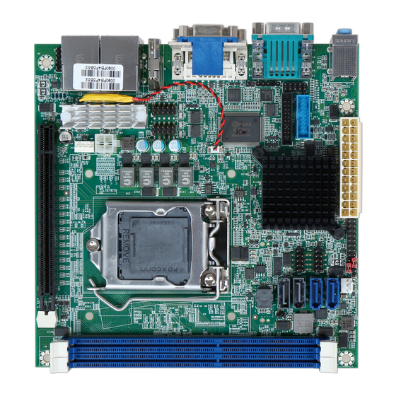
- Page 15 PCIE X16 Connector Support to PCIE Gen2 (H81 Support Gen2 only) Front Pannel Connector External USB 2.0 Connetor External USB 2.0 Connetor System Fan Connector SATA Gen2 Connector Support to SATA Gen2 SATA Gen2 Connector Support to SATA Gen2 WADE-8016 User’s Manual...
- Page 16 CFEX-SPI / SPI Switch ATX Detect &BIOS Recovery Switch Haswell PCH H81 Haswell CPU Socket BIOS Socket Switch with J29 ( CFEX-SPI ) Note: JP3 controll enable the J24 or CFEX JP6 controll boot from the SPI-ROM or CFEX-SPI ROM WADE-8016 User’s Manual...
-
Page 17: Chapter 3 System Installation
Alignment key LGA-1155 CPU In the top, the Yellow Triangle of the CPU is Pin1. Notch Please remember to locate the alignment keys on the CPU socket of the motherboard and the notches on the CPU. WADE-8016 User’s Manual... - Page 18 Before install the CPU, please make sure to turn off the power first!! 1. Open the load lever. 2. Lift the load lever up to fully open 3. Remove the plastic cap on the CPU socket. Before you install the CPU, always cover it to protect the socket pin. WADE-8016 User’s Manual...
- Page 19 4. After confirming the CPU direction for correct mating, put down the CPU in the socket housing frame. Note that alignment keys are matched. 5. Make sure the CPU has been seated well into the socket. If not, take out the CPU and reinstall. WADE-8016 User’s Manual...
- Page 20 System Installation 6. Engage the load lever while pressing down lightly onto the load Plate WADE-8016 User’s Manual...
-
Page 21: Main Memory
8. Please make sure four hooks are in proper position before you install the core Main Memory WADE-8016 has two 240 pin DIMM sockets which supports Dual channel 1333/1600 DDR3-SDRAM as main memory, Non-ECC (Error Checking and Correcting), non-register functions. The maximum memory can be up to 16GB. -
Page 22: Installing The Mini-Itx Board Computer
3.3.1 Chipset Component Driver WADE-8016 uses Intel Lynx Point. It’s a new chipset that some old operating systems might not be able to recognize. To overcome this compatibility issue, for Windows Operating Systems such as Windows 7, please install its INF before any of other Drivers are installed. -
Page 23: Clear Cmos Operation
System Installation Clear CMOS Operation The following table indicates how to enable/disable Clear CMOS Function hardware circuit by putting jumper in the board. PIN No. Signal Description 1-2 short Normal 2-3 short Clear CMOS WADE-8016 User’s Manual... -
Page 24: Wdt Function
Definitions of Variables: Value of Count-mode Register: 0x00 Count down in seconds (Bit3 = 0) 0x08 Count down in minutes (Bit3 = 1) Value of Time-out Value Register 0x00 Time-out Disable 0x01~0xFF Value for counting down ************************************************/ WADE-8016 User’s Manual... -
Page 25: Gpio
//If mode is GPO, set value if(mode == GPIO_MODE_OUT){ outp(EFER, GPIO_DATA_REG); //Select GPIO3 Data Register outp(EFER + 1,(inp(EFER + 1) & ~tmp) | (tmp * value));//Set GPO value, 0:low 1:high printf("GPIO_Pin_Set: Set GPIO(%d) to GPO, Value = %d\n", pin_num, value); WADE-8016 User’s Manual... - Page 26 System Installation else{ printf("GPIO_Pin_Set: Set GPIO(%d) to GPI\n", pin_num); //Exit the Extended Function Mode outp(EFER, 0xAA); return 0; WADE-8016 User’s Manual 3-10...
-
Page 27: Chapter 4 Bios Setup Information
Chapter 4 BIOS Setup Information WADE-8016 is equipped with the AMI BIOS stored in Flash ROM. These BIOS has a built-in Setup program that allows users to modify the basic system configuration easily. This type of information is stored in CMOS RAM so that it is retained during power-off periods. -
Page 28: Main
The date format is <Day>, <Month> <Date> <Year>. Use [+] or [-] to configure system Date. System Time View or set system time The time format is <Hour> <Minute> <Second>. Use [+] or [-] to configure system Time. WADE-8016 User’s Manual... -
Page 29: Configutation
BIOS Setup Information Configutation Setup Warning: Setting items on this screen to incorrect values may cause system to malfunction! CPU Configuration WADE-8016 User’s Manual... - Page 30 When enable, a VWM can utilize the additional hardware capabilities provide by Vander pool Technology. Choices: Disable, Enable. EIST Disable/Enable Intel Speed Step Choices: Disable, Enable. Turbo Mode Turbo Mode Choices: Disable, Enable. CPU C States Disable or Enable CPU C states Choices: Disable, Enable. Chipset Configuration WADE-8016 User’s Manual...
- Page 31 Check to enable VT-d function on MCH. Choices: Disabled, Enabled. Port 80h Redirection [LPC Bus] Forward I/O Port 80 to LPC. Choices: LPC Bus. AMT Configuration Intel AMT Enable or disable Intel Active Management Technology BIOS Extension. Choices: Disabled, Enabled. WADE-8016 User’s Manual...
- Page 32 BIOS Setup Information Un-Configure ME OEMFlag Bit 15:Un-Configure ME without password. Choices: Disabled, Enabled. Disable ME Set ME to Soft Temporary Disabled. Choices: Disabled, Enabled. Memory Information WADE-8016 User’s Manual...
- Page 33 Controls the execution of UEFI and Legacy PXE OpROM Choices: Disable, UEFI only, Enable. RTL8111G-CG PCIE LAN Controller #1~#2 Control the PCI Express Root Port Choices: Disabled, Enabled. Wake on LAN Enable or disable the wake on LAN feature Choices: Disabled, Enabled. WADE-8016 User’s Manual...
- Page 34 Keep IGD enabled based on the setup options. Choices: Auto, Disable, Enable. Aperture Size Select the Aperture Size Choices: 128MB, 256MB, 512MB. DVMT Pre-Allocated Select DVMT 5.0 Pre-Allocated (Fixed) Graphics Memory sized used by the Internal Graphic Device WADE-8016 User’s Manual...
- Page 35 PCI Latency Timer Value to be programmed into PCI Latency Timer Register Choices: 32PCI Bus Clocks, 64PCI Bus Clocks, 96PCI Bus Clocks, 128PCI Bus Clocks, 160PCI Bus Clocks, 192PCI Bus Clocks, 224PCI Bus Clocks, 248PCI Bus Clocks. WADE-8016 User’s Manual...
- Page 36 CPU PCI Express Configuration PEG0 – Gen X Configure PEG0 B0:D0:F0 Gen1-Gen3 Choices: Auto, GEN1, GEN2. PEG0-ASPM Control ASPM support for the PEG Device. Choices: Disable, Auto, ASPM L0s, ASPM L1,ASPM L0sL1. Enable PEG Choices: Disable, Enable, Auto WADE-8016 User’s Manual 4-10...
- Page 37 SATA Controller Speed Indicates the maximum speed the SATA controller can support Choices: Default, Gen1, Gen2, Gen3 Serial ATA Port 0/1/2/3 Capability Port 0/1/2/3 Choices: Enable, Disable. Hot Plug Designates this port as Hot Pluggable Choices: Enable, Disable. WADE-8016 User’s Manual 4-11...
- Page 38 Identify the SATA port is connected to Solid State Drive or Hard Disk Drive. Choices: Hard Disk Drive, Solid State Drive. USB Configuration USB Configuration settings Legacy USB Support Enable legacy USB support. Choices: Enable, Disable, Auto. USB3.0 Support External Enable/disable USB3.0 (XHCI) Controller support Choices: Enable, Disable WADE-8016 User’s Manual 4-12...
- Page 39 BIOS Setup Information XHCI Hand-off Choices: Enable, Disable. EHCI Hand-off Choices: Enable, Disable. USB Mass Storage Drive Support Choices: Enable, Disable. PCH USB Configuration USB Port #0~#9 Disable USB port Choices: Disable, Enable. WADE-8016 User’s Manual 4-13...
- Page 40 Select ACPI sleep state the system will enter when the suspend button is pressed. Choices: S3 only(suspend to RAM) Wake system with Fixed Time Enable or disable system wake on alarm event. Choices: Disable, Enable. Wake on Ring Enable or disable wake on ring from S5. Choices: Disable, Enable. WADE-8016 User’s Manual 4-14...
-
Page 41: Tpm Configuration
BIOS Setup Information TPM Configuration Security device support Enable or disable BIOS support for security device. Choices: Disable, Enable. Super IO Configuration WADE-8016 User’s Manual 4-15... - Page 42 Choices: Disable, Enable. System fan mode Smart fan mode select Choices: Thermal CruiseTM Mode, Fan Speed CruiseTM Mode System Target Temp System fan target temperature range =0~127 System Tolerance Temp System fan Tolerance temperature range = 0~15 WADE-8016 User’s Manual 4-16...
- Page 43 System fan target temperature range =0~127 CPU Tolerance Temp System fan Tolerance temperature range = 0~15 Case Open Warning Support case open warning beep Choices: Disable, Enable. Serial Port Console Redirection Console redirection Choices: Disable, Enable. WADE-8016 User’s Manual 4-17...
-
Page 44: Boot
INT19 Trap Response Bios reaction on INT19 trapping by option ROM: IMMEDIATE-execute the trap right away; POSTPONED-execute the trap during legacy boot. Choices: IMMEDIATE, POSTPONED. Launch Storage OpROM Control the of storage oprom enable/ disable Choices: Disable, Enable. WADE-8016 User’s Manual 4-18... - Page 45 Choices: Disable, Enable. Boot mode select Select boot mode legacy/UEFI Choices: Legacy/UEFI Boot Option #1~#7 Select the system boot order Choices: Hard Disk, CD/DVD, USB Hard Disk, USB CD/DVD, USB Key, USB WADE-8016 User’s Manual 4-19...
-
Page 46: Security
BIOS Setup Information Security Administrator Password Set administrator password User password WADE-8016 User’s Manual 4-20... -
Page 47: Save & Exit
BIOS Setup Information Save & Exit Save Changes and reset Reset the system after saving the changes Disable changes and reset Reset system setup without saving any changes Restore defaults Restore/load default values for all the setup option WADE-8016 User’s Manual 4-21... -
Page 48: Chapter 5 Troubleshooting
To make sure that you have a successful start with WADE-8016, it is recommended, when going with the boot-up sequence, to hit “Del” key and enter the BIOS setup menu to tune up a stable BIOS configuration so that you can wake up your system far well. -
Page 49: Faq
BIOS setting that Portwell has highly endorsed. As a matter of fact, users can load the default BIOS setting any time when system appears to be unstable in boot up sequence. - Page 50 COM2 IRQ 4 NEWMOUSE COM1 IRQ 5 Usable IRQ 【Unassigned】 IRQ 6 System ROM Diskette Event IRQ 7 Usable IRQ 【Unassigned】 IRQ 8 System ROM Real-Time Clock IRQ 9 Usable IRQ 【Unassigned】 IRQ 10 Usable IRQ 【Unassigned】 WADE-8016 User’s Manual...
- Page 51 Troubleshooting IRQ 11 Video ROM Usable IRQ IRQ 12 NEWMOUSE IBM Mouse Event IRQ 13 System ROM Coprocessor Error IRQ 14 System ROM Hard Disk Event IRQ 15 Usable IRQ 【Unassigned】 WADE-8016 User’s Manual...
Need help?
Do you have a question about the WADE-8016 and is the answer not in the manual?
Questions and answers